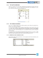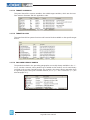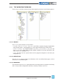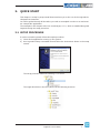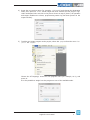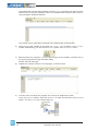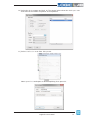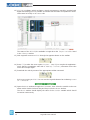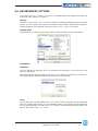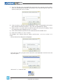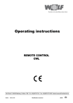
1
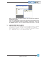
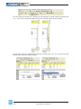
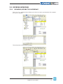
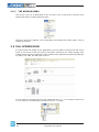
1.
OVERVIEW
LogicLab is an IEC61131-3 Integrated Development Environment supporting the whole
UDQJHRIODQJXDJHVGH¿QHGLQWKHVWDQGDUG
In order to support the user in all the activities involved in the development of an application, LogicLab includes:
- WH[WXDO VRXUFH FRGH HGLWRUV IRU WKH ,QVWUXFWLRQ /LVW EULHÀ\ ,/ DQG 6WUXFWXUHG 7H[W
EULHÀ\67SURJUDPPLQJODQJXDJHVVHH&KDSWHU
- JUDSKLFDOVRXUFHFRGHHGLWRUVIRUWKH/DGGHU'LDJUDPEULHÀ\/')XQFWLRQ%ORFN'LDJUDP EULHÀ\ )%' DQG 6HTXHQWLDO )XQFWLRQ &KDUW EULHÀ\ 6)& SURJUDPPLQJ ODQJXDJHVVHH&KDSWHU
- a compiler, which translates applications written according to the IEC standard directly
into machine code, avoiding the need for a run-time interpreter, thus making the proJUDPH[HFXWLRQDVIDVWDVSRVVLEOHVHH&KDSWHU
- a communication system which allows the download of the application to the target
HQYLURQPHQWVHH&KDSWHU
- a rich set of debugging tools, ranging from an easy-to-use watch window to more powerful tools, which allows the sampling of fast changing data directly on the target environment, ensuring the information is accurate and reliable (see Chapter 9.).
1.1 THE WORKSPACE
7KH¿JXUHEHORZVKRZVDYLHZRI/RJLF/DE¶VZRUNVSDFHLQFOXGLQJPDQ\RILWVPRUHFRPmonly used components.
Workspace
window
Output window
Source code
editors
Document bar
Library window
LogicLab user manual
Watch window
Status bar
1
The following paragraphs give an overview of these elements.
1.1.1
THE OUTPUT WINDOW
The Output window is the place where LogicLab prints its output messages. This window
contains four tabs: Build, Find in project, Debug, and Resources.
Build
The Build panel displays the output of the following activities:
- RSHQLQJDSURMHFW
- FRPSLOLQJDSURMHFW
- downloading code to a target.
Find in project
This panel shows the result of the Find in project activity.
Debug
The Debug panel displays information about advanced debugging activities (for example,
breakpoints).
Resources
The ResourcesSDQHOGLVSOD\VPHVVDJHVUHODWHGWRWKHVSHFL¿FWDUJHWGHYLFH/RJLF/DELV
interfacing with.
1.1.2
THE STATUS BAR
The Status bar displays the state of the application at its left border, and an animated
control reporting the state of communication at its right border.
1.1.3
THE DOCUMENT BAR
The Document bar lists all the documents currently open for editing in LogicLab.
2
LogicLab user manual
1.1.4
THE WATCH WINDOW
The Watch window is one of the many debugging tools supplied by LogicLab. Among the
other debugging tools, it is worth mentioning the Oscilloscope (see Paragraph 9.2), triggers, and the live debug mode (see Paragraph 9.4).
1.1.5
THE LIBRARY WINDOW
The Library window contains a set of different panels, which fall into the categories explained in the following paragraphs.
You can choose the display mode by clicking the right button of your mouse. In the View
list mode, each element is represented by its name and icon. Instead, a table appears
in the View details mode, each row of which is associated with one of the embedded
elements. The latter mode also displays the Type (Operator/Function) and the description
of each element.
If you right-click one of the elements of this panel, and you click Object properties from
the dialog box, then a window appears with further details on the element you selected
(input and output supported types, name of input and output pins, etc.).
1.1.5.1 OPERATORS AND STANDARD BLOCKS
7KLVSDQHOOLVWVEDVLFODQJXDJHHOHPHQWVVXFKDVRSHUDWRUVDQGIXQFWLRQVGH¿QHGE\WKH
IEC 61131-3 standard.
LogicLab user manual
3
1.1.5.2 TARGET VARIABLES
This panel lists all the system variables, also called target variables, which are the interIDFHEHWZHHQ¿UPZDUHDQG3/&DSSOLFDWLRQFRGH
1.1.5.3 TARGET BLOCKS
7KLVSDQHOOLVWVDOOWKHV\VWHPIXQFWLRQVDQGIXQFWLRQEORFNVDYDLODEOHRQWKHVSHFL¿FWDUJHW
device.
1.1.5.4 INCLUDED LIBRARY PANELS
The panels described in the preceding paragraphs are usually always available in the Library window. However, other panels may be added to this window, one for each library
included in the current LogicLab project. For example, the picture above was taken from
a LogicLab project having two included libraries, basic.pll and thermmodel.pll (see
also Paragraph 4.7).
4
LogicLab user manual
1.1.6
THE WORKSPACE WINDOW
The Workspace window consists of three distinct panels, as shown in the following picture.
1.1.6.1 PROJECT
The Project panel contains a set of folders:
- Program, Function blocks, Functions: each folder contains Program Organization
8QLWVEULHÀ\328VVHH3DUDJUDSKRIWKHW\SHVSHFL¿HGE\WKHIROGHUQDPH
- Global variables: it is further divided in Variables, I/O Variables, Constants and
Retain variables(DFKIROGHUFRQWDLQVJOREDOYDULDEOHVRIWKHW\SHVSHFL¿HGE\WKH
folder name (see Paragraph 5.2).
- Tasks: this item lists the system tasks and the programs assigned to each task (see
Paragraph 5.3).
1.1.6.2 DEFINITIONS
The Definitions SDQHO FRQWDLQV WKH GH¿QLWLRQV RI DOO XVHUGH¿QHG GDWD W\SHV VXFKDV
structures or enumerated types.
1.1.6.3 RESOURCES
The contents of the Resources panel depends on the target device LogicLab is interfacing
ZLWKLWPD\LQFOXGHFRQ¿JXUDWLRQHOHPHQWVVFKHPDVZL]DUGVDQGVRRQ
LogicLab user manual
5
1.1.7
THE SOURCE CODE EDITORS
The LogicLab programming environment includes a set of editors to manage, edit, and
SULQW VRXUFH ¿OHV ZULWWHQ LQ DQ\ RI WKH SURJUDPPLQJ ODQJXDJHV GH¿QHG E\ WKH ,(&
61131-3 standard (see Chapter 6.).
7KHGH¿QLWLRQRIERWKJOREDODQGORFDOYDULDEOHVLVVXSSRUWHGE\VSHFL¿FVSUHDGVKHHWOLNH
editors.
6
LogicLab user manual
2.
QUICK START
This chapter is a step-by-step tutorial that introduces you to the use of the LogicLab development environment.
You will be guided through all the tasks you need to accomplish in order to run and monitor a simple PLC application.
The examples in this chapter refer to a virtual target, VPLC1, which is installed along with
LogicLab during the setup procedure.
2.1 SETUP PROCEDURE
In order to install LogicLab, follow this simple procedure:
1)
Close all the applications running on the system.
2)
5XQ/RJLF/DE¶VVHWXSH[HFXWDEOH¿OHDQGIROORZWKHLQVWUXFWLRQVVKRZQLQWKHVHWXS
wizard.
The setup procedure adds the following Start menu.
7KH/RJLF/DE¶VIROGHULQWKH¿OHV\VWHPKDVWKHIROORZLQJVWUXFWXUH
LogicLab user manual
7
2.2 USING THE IDE
The following steps show you how to create, run and debug a simple LogicLab PLC program. The program will be written in the ST language and will be executed directly on
your machine. A virtual target, VPLC1, has been installed by the setup procedure. VPLC1
emulates a simple programmable controller provided with digital and analog I/O.
1)
Launch LogicLab from the Start menu.
2)
:KHQ/RJLF/DELVVWDUWHGIRUWKH¿UVWWLPHQRWDOOZLQGRZVDQGWRROEDUVDUHVKRZQ
<RXFDQFXVWRPL]H/RJLF/DE¶VZRUNVSDFHWKURXJKWKHView menu.
3)
In order to create a new project, select the item New project from the menu File.
8
LogicLab user manual
4)
Insert the new project name (for example, PlcExample) and choose the destination
folder, then press OK. VPLC1 virtual target has been selected for this project. LogiF/DE¶VZRUNVSDFHORRNVQRZOLNHLQWKHSLFWXUHVKRZQDWVWHSWKDWLVDOORSHUDWRUV
and target variables are shown, preprocessing status log has been printed in the
output window).
5)
To add a new empty program to the project, select New program from the menu Project > New object.
Choose the ST language, insert the new program name (for example, Main), and
press OK.
It is also possible to assign here the program to one of the available tasks.
LogicLab user manual
9
LogicLab shows now the editor window of the Main program object. On the top of the
window there is the local variables editor. The variables editor allows to add, remove,
FRS\DQGSDVWHYDULDEOHGH¿QLWLRQV
The textual source code editor is placed in the bottom part of the window.
6)
Insert a new local variable by pressing the Insert record button in the Project
toolbar. Alternatively, you can use the Insert option of the Variables menu.
7)
Edit the name (for example, Counter) and the type of the variable. A double-click in
WKHW\SH¿HOGRSHQVWKHW\SHVHOHFWLRQGLDORJ
Choose the INT data type.
8)
9)
Implement a simple counter in ST language, as shown below.
In order to be executed, the program Main has to be assigned to a task.
In the Workspace window, right-click on the Slow task and select the Add program
option. The Object browser window pops up.
10
LogicLab user manual
10) Select the Main program and click OK. The picture below shows the Workspace window after the successful completion of the operation.
11) Select Simulation mode from Debug menu.
Name your VPLC1 workspace as PLCExampleWsp, then press OK.
LogicLab user manual
11
12) VPLC1 is a software which emulates a simple programmer controller provided with
digital and analog I/O. It is possible to interact with simulator as explained in Simu/DEPDQXDORUEULHÀ\LQResources tab.
The status of the VPLC1 I/O is available in LogicLab as the Target variables listed
in the Library window.
13) With LogicLab connect to VPLC1 through the apposite button on the toolbar.
14) Press F7 (or select the menu option Project - Compile) to compile the application.
Verify that the compilation ends with 0 warning - 0 errors, otherwise correct the
errors and compile again.
15) Download the code by means of the appropriate toolbar command.
PLC is now running on VPLC1. You can see the LogicLab bottom bar indicating Source
ok - Connected.
16) Open the Watch window through the View menu, then select the variable in the text
editor with a double-click and drag and drop it into the Watch window.
The Watch window should display the value of the Counter variable which should
increment continuously.
12
LogicLab user manual
You are at the end of this very simple but complete (edit-compile-download-debug) working session with LogicLab.
Further steps you should take in order to acquire a deeper knowledge of the tool include
the use of the other languages, function & function blocks, global variables, libraries, real
time debugging and so on. Refer to the following sections of this manual to obtain the
necessary information.
2.3 A MORE COMPLEX EXAMPLE
In the SampleProjects\SampleVXEGLUHFWRU\RI\RXU/RJLF/DELQVWDOODWLRQ\RXFDQ¿QGD
more complex VPLC1 example, which offers an overview of IEC 61131-3 languages.
To open the project use the File - Open project menu option and open VPLC1Sample.
ppjs or select it from Example projects list in the welcome page.
LogicLab user manual
13
14
LogicLab user manual
3.
USING THE ENVIRONMENT
This chapter shows you how to deal with the many UI elements LogicLab is composed of,
LQRUGHUWROHW\RXVHWXSWKH,'(LQWKHZD\ZKLFKEHVWVXLWVWR\RXUVSHFL¿FGHYHORSPHQW
process.
3.1 LAYOUT CUSTOMIZATION
7KHOD\RXWRI/RJLF/DE¶VZRUNVSDFHFDQEHIUHHO\FXVWRPL]HGLQRUGHUWRVXLW\RXUQHHGV
/RJLF/DEWDNHVFDUHWRVDYHWKHOD\RXWFRQ¿JXUDWLRQRQDSSOLFDWLRQH[LWLQRUGHUWRSHUVLVW
your preferences between different working sessions.
3.2 TOOLBARS
3.2.1
SHOWING/HIDING TOOLBARS
In details, in order to show (or hide) a toolbar, open the View>Toolbars menu and select
the desired toolbar (for example, the Function Block Diagram bar).
The toolbar is then shown (hidden).
3.2.2
MOVING TOOLBARS
You can move a toolbar by clicking on its left border and then dragging and dropping it to
the destination.
The toolbar shows up in the new position.
LogicLab user manual
15
You can change the shape of the toolbar, from horizontal to vertical, either by pressing the
Shift key or by moving the toolbar next to the vertical border of any window.
<RXFDQDOVRPDNHWKHWRROEDUÀRDWHLWKHUE\SUHVVLQJWKH CTRL key or by moving the
toolbar away from any window border.
16
LogicLab user manual
3.3 DOCKING WINDOWS
3.3.1
SHOWING/HIDING TOOL WINDOWS
The View>Tool windows menu allows you to show (or hide) a tool window (for example,
the Output window).
The tool window is then shown (hidden).
LogicLab user manual
17
3.3.2
MOVING TOOL WINDOWS
In order to move a tool window, click on its name (at the top of the window) and then drag
and drop it to the destination.
<RXFDQPDNHWKHWRROZLQGRZÀRDWE\GRXEOHFOLFNLQJRQLWVQDPHRUE\SUHVVLQJWKH
CTRL key, or by moving the tool window away from the main window borders.
A tool window can be resized by clicking-and-dragging on its border until the desired size
is reached.
18
LogicLab user manual
3.4 WORKING WITH WINDOWS
LogicLab allows to open many source code editors so that the workspace could get rather
messy.
You can easily navigate between these windows through the Document bar and the Window menu.
3.4.1
THE DOCUMENT BAR
The Document bar allows to switch between all the currently open editors, simply by clicking on the corresponding name.
You can show or hide the Document bar with the menu option of the same name in the
menu View>Toolbars.
LogicLab user manual
19
3.4.2
THE WINDOW MENU
The Window menu is an alternative to the Document bar: it lists all the currently open
editors and allows to switch between them.
Moreover, this menu supplies a few commands to automate some basic tasks, such as
closing all windows.
3.5 FULL SCREEN MODE
In order to ease the coding of your application, you may want to switch on the full screen
mode. In full screen mode, the source code editor extends to the whole working area,
making easier the job of editing the code, notably when graphical programming languages (that is, LD. FBD, and SFC) are involved.
You can switch on and off the full screen mode with the Full screen option of the menu
View or with the corresponding command of the Main toolbar.
20
LogicLab user manual
3.6 ENVIRONMENT OPTIONS
If you click Options... in the File menu, a multi-tab dialog box appears and lets you
customize some options of LogicLab.
General
Autosave: if the Enable Autosave box is checked, LogicLab periodically saves the whole
project. You can specify the period of execution of this task by entering the number of
minutes between two automatic savings in the Autosave interval text box.
Graphic Editor
This panel lets you edit the properties of the LD, FBD, and SFC source code editors.
Text Editors
Language
You can change the language of the environment by selecting a new one from the list
shown in this panel.
After selecting the new language, press the Select EXWWRQ DQG FRQ¿UP E\ FOLFNLQJ OK.
This change will be effective only the next time you start LogicLab.
Tools
You can add up to 16 commands to the Tools menu. These commands can be associated
with any program that will run on your operating system. You can also specify arguments
for any command that you add to the Tools menu. The following procedure shows you
how to add a tool to the Tools menu.
LogicLab user manual
21
1)
7\SHWKHIXOOSDWKRIWKHH[HFXWDEOH¿OHRIWKHWRROLQWKH Command text box. OtherZLVH\RXFDQVSHFLI\WKH¿OHQDPHE\VHOHFWLQJLWIURP:LQGRZV([SORUHUZKLFK\RX
open by clicking the Browse button.
2)
In the Arguments text box, type the arguments - if any - to be passed to the executable command mentioned at step 1. They must be separated by a space.
3)
Enter in Menu string the name you want to give to the tool you are adding. This is
the string that will be displayed in the Tools menu.
4)
Press Add to effectively insert the new command into the suitable menu.
5)
Press OKWRFRQ¿UPRUCancel to quit.
For example, let us assume that you want to add Windows calculator to the Tools
menu:
- )LOOWKH¿HOGVRIWKHGLDORJER[DVGLVSOD\HG
- Press Add. The name you gave to the new tool is now displayed in the list box at the
top of the panel.
And in the Tools menu as well.
22
LogicLab user manual