1
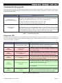
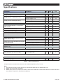
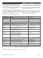
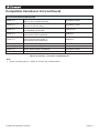
Active DST Module: Digital signal processing for Depth, Speed and Temperature transducers DST-2-C User Manual Issue 1.40 Breathes new digital life into old and new analogue transducers Connects to depth sounder transducers to produce NMEA 0183 depth sentences DBT and DPT Connects to log hall-effect sensors to produce NMEA 0183 speed and distance travelled sentences VHW and VLW Connects to 10kΩ @ 25ºC temperature sensors to produce NMEA 0183 temperature sentences MTW Active DST Module - DST-2-C Contents Important Notices Notices Foreword Introduction General features 4 4 4 4 5 Technical features Software updates Connecting devices together 5 5 6 Connections Connecting to NMEA devices 7 8 Other Connections 9 Depth transducer interface Speed transducer interface Temperature transducer interface The basics The NMEA signals The different NMEA standards Depth transducer input/outputs Speed/Log transducer input/outputs Temperature transducer inputs NMEA 0183 Output RS232 (PC) compatible Output Connecting to the battery supply Cable grommets 5 5 5 6 6 6 8 8 8 9 9 9 9 Using the ActiPatch upgrade utility 10 Troubleshooting guide Specifications Compatible Transducer List Order part numbers Company Information 11 12 13 16 16 Main Window Availability Connecting for re-programming © 2009 Active Research Limited 10 10 10 Page 3 Important Notices Actisense and the Actisense logo are registered trademarks of Active Research Limited. All rights are reserved. The contents of this manual may not be transferred or copied without the expressed written permission of Active Research Limited. All other trademarks are the property of their respective owners. The Actisense Depth, Speed and Temperature module (DST-2) is intended for use in a marine environment, primarily for below deck use. If the unit is to be used in a more severe environment, such use may be considered misuse under the seller’s warranty. The Actisense DST-2 has been certified to comply with the European directive for Electro-Magnetic Compatibility (EN60945), and is appropriately CE marked. Operation of the unit should be in conjunction with appropriate CE approved shielded connectors and cabling used in accordance with the CE directive EN60945. Any EMC related issues should be reported to Active Research immediately to allow the company to rectify or resolve EMC related problems in accordance with its obligations under EN60945. If the unit is connected such that compliance failure occurs beyond the company’s control, the company shall not be held responsible for compliance failure until suitable EMC guidelines for connection are seen to have been taken. Warning: Depth sounders are not designed to perform as navigational instruments, nor as devices to avoid grounding a vessel. Any such use of the Actisense depth output is at the vessel owner’s own risk, and no responsibility will be accepted for any resulting damage or personal injury. Always use caution when operating in shallow areas and maintain a very slow speed. Be aware that the depth may change more quickly than your ability to react and avoid grounding the vessel. Notices When using this document, keep the following in mind: The products described in this manual and the specifications thereof may be changed without prior notice. To obtain upto-date information and/or specifications, contact Active Research Limited or visit the Actisense website (www. actisense.com). Active Research Limited will not be liable for infringement of copyright, industrial property right, or other rights of a third party caused by the use of information or drawings described in this manual. © 2009 Active Research Limited Active Research Limited will not be held responsible for any damage to the user that may result from accidents or any other reasons during operation of the user’s unit according to this document. Foreword Actisense recognises that instructions are often skipped, so we have aimed to write this document in an informative, yet direct manner that will aid the user. We have tried to cover all the points a typical user may need to know. Please read all sections before installing and using the Actisense DST module product and any related software programs. Introduction The Actisense Depth, Speed and Temperature module (DST-2) was developed to breathe new digital life into old and new analogue (standard, passive, no electronics) transducers. By adding an advanced digital signal processing (DST) module to standard analogue transducers, they can interface directly with any instrument with an NMEA 0183 digital data input. The NMEA 0183 marine standard is a purely digital data transmission scheme, using binary format ‘1’s and ‘0’s, to communicate a digital representation of the required information (depth, speed etc.) to a connected instrument. A depth sounder transducer is a sensor that must be interfaced to a depth sounder circuit, capable of both producing the high voltages to drive the depth transducer, yet have very sensitive circuitry to receive the faint echoes of the sound reflected from the sea-bed. Such a depth sounder circuit also needs a powerful software algorithm to track the sea-bed, and reject false signals that occur throughout the ocean. For example, an unsophisticated depth sounder device can lock on to a false sea-bed due to reflections from nearby targets, other depth sounder devices working on the same frequency, double depths and even algae formations. Actisense has designed and improved their current depth sounder circuitry and software over a development period spanning 15 years. The algorithms have now been proven in tens of thousands of products throughout the world that Actisense has either manufactured itself, or has played an important design consultancy role in. To that, Actisense has added speed and temperature transducer interfaces to the system. This creates a feature rich product that benefits the prospective user. The resulting module can measure the four quantities of depth, speed, log (distance) and temperature in one device and so save the cost of the extra electronic devices. The NMEA 0183 port requirements of the receiving instrument are also reduced from three to just one. Page 4 Active DST Module - DST-2-C Full information on the complete Actisense product range can be found on the Actisense website. General features Depth transducer interface Connects to a standard piezoelectric depth transducer crystal element using a three-wire interface. Generates the high transmit voltages, and receives the weak echo returns from the sea-bed. Using an advanced sea-bed tracking algorithm, the depth value is determined and output as NMEA 0183 depth sentences DBT and DPT. Speed transducer interface Connects to a standard ‘paddle-wheel’ hall-effect speed transducer using a three-wire interface. Generates the required power supply, and receives the pulse signal from the paddle-wheel. Using statistical analysis, the speed and distance values are determined and output as NMEA 0183 speed and distance travelled sentences VHW and VLW. Temperature transducer interface Connects to a standard thermistor transducer using a twowire interface. Using a very high resolution algorithm, the temperature value is determined and output as NMEA 0183 temperature sentence MTW. Technical features High-speed microcontroller capable of 10 million instructions per second. More than enough power to perform all the processing required to produce the accurate and very fast tracking depth output of the system, in addition to the speed, distance and temperature calculations. Flash ROM technology that supports automatic programming for quick and easy updates, 10,000+ erase cycles and a 10-year Data Retention provides carefree user configuration. Sounding transducer circuitry capable of interfacing to a wide selection of transducers, including Airmar (www. airmar.com). Refer to the Compatible transducer list section for further details. Wide battery input voltage range to offer maximum compatibility, the NMEA 0183 DST-2 can operate from a battery supply anywhere between 10 and 28 volts. Low Power Consumption - typically 65mA at 12 volts. Very tough Polycarbonate case is certified to IP66 (classified as “totally protected against dust and protection against low pressure jets of water from all directions”). Being Polycarbonate, it is also incredibly strong, offering a wide temperature range and superior protection to the electronics inside. The IP66 rating of the case is only limited by the sealing gasket strip, which can be enhanced by applying a suitable non-acid based marine sealant to the gasket after wiring and testing. This will allow use of the unit in areas where salt spray could enter, accidental immersion may occur, or in environments where maximum long-term reliability is paramount. Robust Nylon grommets are certified to IP68 (classified as immersible for long periods without water ingress). Note that to achieve this level of water integrity all grommets must be occupied by round-section cables. Large range of possible cable diameters of between 4.5mm and 10mm, single or multi-pair wire types can be easily accepted. Software updates The DST-2’s built-in firmware is held in “flash” memory, allowing quick and easy upgrades using a simple Microsoft Windows (95/98/ME/NT/2000/XP) user interface program (ActiPatch) running on a connected PC. It is our policy to provide these updates free on our website, www.actisense.com, so that your DST module can become more sophisticated with time, and should there be any bugs reported in the software, they can be promptly fixed without the unit coming out of commission. This upgrade can be performed with the unit completely in-situ, via a PC connected to the NMEA 0183 port with the Actisense RS485-to-RS232 converter cable. NMEA 0183 full-differential output driver. This can drive up to 4 fully compliant NMEA 0183 device loads, with a 10mA (maximum) drive capability. The full-differential output ensures better quality communications and lower noise emissions on unshielded twisted pair cabling. This connection also allows the unit to be updated via the free flash upgrade software available on the Actisense website if the DST-2 software requires an update. © 2009 Active Research Limited Page 5 Connecting devices together The basics NMEA data is transmitted from an information source such as GPS, depth sounder, gyro compass etc. These data sending devices are called “Talkers”. Equipment receiving this information such as a chartplotter, radar or NMEA display is called a “Listener”. Unfortunately, only one Talker can be connected on to a single NMEA 0183 system at any one time. Two or more Talkers are simply not possible because they are not synchronised to each other, and will attempt to ‘talk’ at the same time (over each other), resulting in corruption of the NMEA data, and potentially in disaster if valuable data such as navigation information is lost or corrupted so that it is incorrect and/or misleading. The different NMEA standards The NMEA 0183 specification has slowly evolved over the years, so connecting one device to another is not always a straight forward matter. The earlier versions of NMEA 0183 (before v2.0, as detailed above), used slightly different connection methods and signal levels: the instruments had just one “NMEA” data line (‘Tx’ or ‘Out’), and used the ground as the other line - similar to the way a computer serial port works. This connection method is referred to as “single ended” instead of the “differential” method used by NMEA 0183 v2.0 devices. The data format is largely the same between both systems, with v2.0 adding some extra sentence strings, and removing older (redundant) sentence strings from the specification. The situation is further complicated, as many manufacturers still use the old (“single ended”) method of connection because it is cheaper to implement. Actisense produces a full range of products to solve all NMEA interfacing requirements. So how can an older type NMEA device be connected to a newer type device? Please visit the Actisense website for full details on these and other Actisense interfacing, Depth sounding and Sonar products. Care is needed – it is possible to damage or overload the output of a newer differential device if it is incorrectly connected to an older device. This is because the older devices used ground as the return, whereas the newer devices actually drive the NMEA “-/B” line between 5v and 0v. Thus, connecting this output to ground will result in high currents being drawn by the driver instrument, resulting in potential overheating and damage to the driver circuits. The NMEA signals The NMEA 0183 system v2.0 and later uses a ”differential” signalling scheme, whereby two wires are used to transmit the NMEA data. These connections will be labelled as either NMEA “A” and “B“ or NMEA “+” and “-“ respectively, depending on the instrument and manufacturer. When connecting between different manufacturers, there can be some confusion, but it is simple and easy to remember: NMEA “A” connects to NMEA “+” and NMEA “B“ connects to NMEA “-“. To connect a new type differential device to an old type single-ended system, connect the NMEA “+/A” output from the differential driver to the single-ended NMEA “Rx” or “In” input of the device. Leave the NMEA “-/B” output floating. Connect the ground line of the differential output device to the ground of the single-ended device. This provides the required data signal return current path. To connect an old type single-ended device to a new type differential device, connect the NMEA ”Tx” or “Out” output from the single-ended driver to the differential NMEA “+/A” input of the device. Connect the ground line of the single-ended output device to the NMEA “-/B” input of the differential device. This provides the data signal return current path. If the NMEA “-/B” input is left floating, then data corruption / errors may occur. Please refer to the Other Connections section for example of these connection methods. © 2009 Active Research Limited Page 6 Active DST Module - DST-2-C Connections DST-2-C-200 NMEA DST MODULE 99999 Figure 1 – All external connections The DST module (DST-2) has screw-terminal “Phoenix” type external connections for: 1. Depth transducer input/outputs. The three-wire connection type is flexible enough to interface to most standard piezoelectric crystal depth transducers. 2. Speed transducer input/output. The standard three-wire connection type should easily interface to most standard hall-effect paddlewheel speed transducers. 3. Temperature transducer inputs. The standard two-wire connection type should easily interface to most standard thermistor type temperature transducers. 4. An NMEA 0183 data output. The NMEA 0183 output comprises of two connections: ‘+/A’, ‘-/B‘ and conforms in full to the NMEA 0183 standard for differential communications. Note: 1. To complete the NMEA 0183 standard all device interconnection NMEA cables used should meet the two-conductor, shielded, twisted pair configuration specification. The shield connection of these wires should be connected at the instrument end only to prevent ground loops. 2. Refer to the Specifications section for the full details on input/output specifications. 3. If a laptop / PC that is to be used with the DST-2 module does not have an RS-232 serial port available, the Actisense USB to RS-232 adapter cable has been tried and tested to provide a compatible communications port, when used in conjunction with the Actisense NMEA Opto-isolator adapter cable. Please visit the Actisense website for full details on these, and other Actisense products. 5. Battery supply input. © 2009 Active Research Limited Page 7 Connecting to NMEA devices + DST-2-C-200 NMEA DST MODULE 99999 Temperature G transducer + G Ps + Speed transducer Depth Sh transducer - Figure 2 – Transducer connections Depth transducer input/outputs Depth transducers have two or three connections: A ‘Live’ connection marked ‘DEPTH TDUCER’ on the PCB, usually a coloured wire on twisted pair cable (Airmar), or the centre conductor on a coaxial cable. A ‘Ground’ connection marked ‘DEPTH GROUND’, often the black core of a twisted pair cable (Airmar). Coaxial cables have a common shield/ground. A ‘Shield’ connection which is the shield of a two-wire cable, or the outer sheath on a coaxial cable. Two-connection transducers only provide the ‘Live’ and ground connections. Whilst the DST-2 will work with these types of depth transducers, the performance obtained may not be as good as that from a transducer with separate shield and ground connections (due to a poorer SNR). Speed/Log transducer input/outputs Log transducers generally have three connections: A pulse connection marked ‘LOG PULSE’ on the DST PCB, supplies the speed pulses relative to speed. A ground connection marked ‘LOG GROUND’, used as a return for the pulse signal and power supply. A power supply connection marked ‘LOG PWR’, supplies the speed transducer with its power. The installer must ensure that this power supply is only connected to the log transducer. Damage may occur if this supply output is incorrectly connected, as it is connected to the sensitive internal DST circuitry. © 2009 Active Research Limited Temperature transducer inputs Thermistor type transducers have two connections: A resistance input connection, marked ‘TEMP’ on the DST-2 PCB. A second resistance connection, marked ‘TEMP GND’, is connected to the other side of the thermistor transducer. The polarity of these two signals is not important. Airmar “Triducer” type sensors share a common ground connection for the speed/log and temperature sensors. If the required transducer does not have a separate ground for log and temperature, simply connect the single ground to the temperature ground marked “TEMP GND” on the DST-2 PCB. Temperature transducers suitable for connection to the DST-2 are of the “thermistor” sensor type with a 10kΩ impedance at 25º Centigrade, as used in all Airmar technology transducers. Note: 1. Wire colours are for guidance only. 2. These connections should be carefully connected to each transducer according to the instructions of the transducer manufacturer(s). Page 8 Active DST Module - DST-2-C Other Connections NMEA Listener A + - Battery/ PSU + - DST-2-C-200 A NMEA Listener B B NMEA DST MODULE G Tx Rx 99999 PC or Laptop (RS232) Figure 3 – NMEA 0183 and Battery connections NMEA 0183 Output The NMEA 0183 buffered output is capable of driving up to 4 NMEA 0183 fully compliant listening devices. NMEA Listener device’s A and B: These devices conform in full to the NMEA 0183 standard and their connection ID’s match that of the DST module. RS232 (PC) compatible Output The RS232 (PC) output can be used to connect to a PC’s communication port using a cable conforming to the following specification: 1. A D-type female (socket) connector for the PC end of the cable. 2. A minimum of 3 cores are required in a shielded cable. Higher quality cable will make longer cable lengths possible. Most typical cables have two twisted pairs inside. In this case, use one pair for the ‘TX’ line and one for the ‘RX’ line. Use the spare wire in each pair as ground, and connect the cable shield to ground only at the computer end. 3. The ‘TX’ of the DST-2 should be connected to the ‘RX’ of the computer (standard D-type, pin 2) and the DST-2 ‘RX’ should be connected to the ‘TX’ of the computer (pin 3). The ‘GROUND’ of the DST-2 should be connected to the PC’s ground (pin 5). © 2009 Active Research Limited Connecting to the battery supply The Actisense DST-2 should be wired to the vessel’s battery supply in the most direct manner possible, to minimize interference from other electronic devices. The cable used should be of sufficient gauge to handle the power requirements of the Actisense DST-2 (refer to the Specifications section). Cable grommets The Actisense DST-2 is provided with Nylon sealing grommets. It is recommended that the box is positioned with the double grommets pointing downwards, so that two cables may exit downwards from the case. This will prevent any moisture from entering the case, as it will drain downwards, and not into the case. The module case lid is IP66 certified and has an integral gasket. If additional protection from water is required, add a small amount of silicon / sicaflex sealant to the lid’s gasket before the lid is screwed to the base. Note: 1. Wire colours are for guidance only. Page 9 Using the ActiPatch upgrade utility The Actisense DST-2 hardware can be easily and quickly updated using the Actisense ActiPatch. The main window has a simple look, as the flash update process has been completely automated for a trouble-free operation. Main Window Figure 4 – ActiPatch upgrade utility main window Availability The current Actisense DST-2 software program is a very mature product that has evolved over the past 8 years, and as such, we believe it has been tested more rigorously than any other depth sounder device currently available. Therefore, the upgrade feature has not yet become active, but everything is in place should it ever be required. Please monitor our Actisense website for possible updates, which will be posted when required. If you would like to join our ‘Actiscope’ newsletter list, you will be kept up to date on the DST-2 and all other Actisense products via a simple e-mail. This part of the document will contain full details of the PC based system for re-programming when it becomes available. © 2009 Active Research Limited Connecting for re-programming The DST-2 hardware should be connected to the PC serial communications port via an Actisense bi-directional RS485-to-RS232 adapter cable, and a battery supply. Please refer to the NMEA 0183 Output section for full connection details. If an Actisense NMEA Data Combiner (Multiplexer) is being used between the PC and the DST, it will have to be bypassed to allow bi-directional communication between the PC and the DST module. Page 10 Active DST Module - DST-2-C Troubleshooting guide This guide will concentrate on all relevant troubleshooting issues above simple cable connection faults. Therefore, the cables between the Actisense DST-2 hardware and any other devices should be checked as a matter of course, before continuing with this guide. Problem / Error condition Required user response Ensure that correct polarity of the NMEA connections have been observed - NMEA connections are polarity sensitive. No damage should be caused if the polarity is reversed, but no NMEA data will be seen on the receiving instrument. No data seen on NMEA instrument display “+” and “A” connections should be wired to the DST’s “+/A”. “-” and “B” connections should be wired to the DST’s “-/B”. Ensure that the PC software is selecting the correct PC Comms port number. No data seen on PC display As a diagnostic, you can use the standard Windows “HyperTerminal” utility to receive NMEA data. By selecting the NMEA DST-2 input comms port, the baud rate to that required (4800 standard), no parity, 1 stop bit, 8 data bits and no flow control, the received NMEA text data from the DST-2 will be shown on the PC screen. Table 1 – Troubleshooting guide Diagnostic LED The NDC-2 hardware supports a tricolour diagnostic LED that indicates the current operating mode of the hardware, or if an error has been detected during the self-test initiation process. Table 2 details what each LED colour represents and if any user interaction is required. LED Colour Mode / Error condition Required user response Normal operation modes The sequence below indicates a successful power-up of the DST-2 and the commencement of data combining. Red, No flashing Start-up mode, No error No response required. A normal operation mode that should last for no more than 1 second. Any longer indicates an error with the main program. Red, No flashing Flash updating mode, No error No response required. LED will stay red for the duration of the flash update operation (using ActiPatch). Once operation completes, the DST-2 hardware will be automatically reset. Amber, No flashing Initialise and self-test mode, No error No response required. A normal operation mode that follows after the Start-up mode and should last for approximately 0.25 seconds (and so may not be visible). Green, No flashing Normal and no data mode, No error Green, Flashing Normal and data Rx mode, No error No response required. A normal operation mode that follows the Initialise and self-test mode. Indicates that no error was detected during the self-test operation. Also indicates that no data is currently being transmitted by the DST-2 hardware. No response required. A normal operation mode that indicates that data is currently being transmitted by the DST-2 hardware. Flash length proportional to amount of data transmitted. Table 2 – Diagnostic LED colours © 2009 Active Research Limited Page 11 Specifications Parameter Conditions Min. Max. Unit 10 28 V Supply voltage = 12v 55 80 mA Supply voltage = 24v 50 80 mA Supply voltage = 12v 70 130 mA Supply voltage = 24v 65 130 mA Logical ‘1’/stop bit 0.0 0.5 V 4.8 5.2 V - 10 mA 50 55 mA 4.8 kbit/sec 1 secs Supply Supply voltage Supply current, no load (see note 1) Supply current, loaded (see note 1) NMEA Output voltage between +/- and ground (see note 2) At maximum load, drive voltage reduces to 2v Output current (see note 2) Output short circuit current. Baud rate - fixed (see note 3) Data output rate Depth Sounder 0-10 Knots, ideal conditions 0.3 100 metres 10-40 Knots, ideal conditions 0.3 100 metres Depth range, using wide-beam sensor (like the Airmar DT800) 0-10 Knots, ideal conditions 0.3 100 metres 10-40 Knots, ideal conditions 0.3 60 metres Depth sounding frequency tolerance Around the designed frequency -2 +2 kHz Sensor dependant 0.5 50 Knots Sensor dependant -10 +50 ºC -20 +70 °C Depth range, using narrow-beam sensor (like the Airmar P66) Speed / Log Speed measurement Temperature Temperature measurement, using 10kΩ @ 25ºC thermistor (all Airmar models) General Ambient temperature Table 3 – DST-2 specifications All specifications are taken with reference to an ambient temperature (TA) of +25°C. Note: 1. The maximum quoted currents are for very short periods (less than 0.5 milliseconds) only. 2. NMEA output is RS-485 compatible. 3. NMEA 0183 inputs and outputs on the DST-2 are fixed to 4800 baud. Custom Baud rates and custom data rates are available if required for specialised installations. © 2009 Active Research Limited Page 12 Active DST Module - DST-2-C Compatible Transducer List This compatibility list is by no means exhaustive - more transducer types and manufacturers are added every month after their compatibility has been proven. Airmar Technology are always expanding and improving their transducer range. Any of the 200kHz model types will work well with the Actisense DST-2-C-200 module, and likewise, any of the 235kHz model types will work well with the Actisense DST-2-C-235 module. The 150kHz DST-2 model has been successfully tested with the EchoPilot Marine and NASA Marine transducers. Seafarer transducers are essentially the same as the NASA model, so should be identical in performance, though this is yet to be proven conclusively. Actisense would like personal feedback of any company using the DST-2 module with a different manufacturer and/ or model type of transducer not included in this list. This feedback will help greatly to expand this list. Airmar do not currently make any 150kHz transducers. Manufacturer Model Ceramic type For use with Actisense DST-2-C-150 Echopilot Marine Standard in-hull stemmed, with oil bath mounting 150 kHz / 30mm circular element NASA Marine Standard in-hull stemmed, with oil bath mounting 150 kHz / 30mm circular element For use with Actisense DST-2-C-200 Airmar (*1) D800 & DT800 through-hull retractable, with P17, B17 or B122 skin-fitting All 200kHz models Airmar (*1) DST800 through-hull retractable, with P17 or B17 skin-fitting All 200kHz models Airmar (*1) P52 & P66 transom mount multisensor & P79 adjustable in-hull depth 200kHz-G Airmar (*1) P19 & B22 through-hull low profile & P39 transom mount multisensor 200kHz-U Airmar (*1) P23 transom mount depth/temp, P319 through-hull low profile, & P32 transom mount multisensor 200kHz-A Airmar (*1) B39, B45 & B46 through-hull stemmed All 200kHz models Airmar (*1) B744V & B744VL through-hull multisensor All 200kHz models Airmar (*1) SS44V, B66V & B66VL multisensor All 200kHz models Airmar (*1) SS505 & SS555 through-hull stemmed All 200kHz models Skipper ETN200FS & ETN200F in-hull depth All 200kHz models Table 4 – Transducer compatibility list Note: 1. Airmar skin-fitting types: P - Plastic, B - Bronze, SS - Stainless Steel © 2009 Active Research Limited Page 13 Compatible transducer list (continued) For use with Actisense DST-2-C-235 Airmar (*1) D800 & DT800 through-hull retractable, with P17, B17 or B122 skin-fitting All 235kHz models Airmar (*1) DST800 through-hull retractable, with P17 or B17 skin-fitting All 235kHz models Airmar (*1) P52 & P66 transom mount multisensor & P79 adjustable in-hull depth 235kHz-C/D Airmar (*1) P19 & B22 through-hull low profile & P39 transom mount multisensor 235kHz-D Airmar (*1) P23 transom mount depth/temp, P319 through-hull low profile, & P32 transom mount multisensor 235kHz-C Airmar (*1) B39, B45 & B46 through-hull stemmed All 235kHz models Airmar (*1) B744V & B744VL through-hull multisensor All 235kHz models Airmar (*1) SS44V, B66V & B66VL multisensor All 235kHz models Airmar (*1) SS505 & SS555 through-hull stemmed All 235kHz models Table 4 (continued) – Transducer compatibility list Note: 1. Airmar skin-fitting types: P - Plastic, B - Bronze, SS - Stainless Steel © 2009 Active Research Limited Page 14 Active DST Module - DST-2-C Notes: © 2009 Active Research Limited Page 15 Order codes: DST-2-150 DST-2-170 DST-2-200 DST-2-235 Actisense 150 kHz DST Module Actisense 170 kHz DST Module Actisense 200 kHz DST Module Actisense 235 kHz DST Module Company Information Active Research Limited 5, Wessex Trade Centre Ringwood Road Poole Dorset UK BH12 3PF Telephone: Fax: 01202 746682 (International : +44 1202 746682) 01202 746683 (International : +44 1202 746683) Actisense on the Web: For advice, support and product details E-mail: Website: [email protected] www.actisense.com “Actisense” is a registered trademark of Active Research Limited. © 2009 Active Research Limited Page 16