1
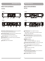
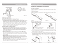
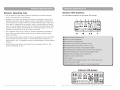
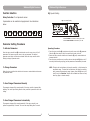
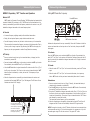
ACT-828 Wideband Dual-Channel Digital Receiver ACT-818 Wideband Single-Channel Digital Receiver User Guide MIPRO Electronics Co., Ltd. Headquarters: 814 Pei-Kang Road, Chiayi, 60096, Taiwan. Web: www.mipro.com.tw E-mail: [email protected] Design and specifications are subject to change without prior notice 2 CE4 5 4 A AS121115 ! IMPORTANT SAFETY INSTRUCTIONS ! 1. Read these instructions. 2. Keep these instructions. 3. Heed all warnings. 4. Follow all instructions. 5. Do not use this apparatus near water. 6. Clean only with a dry cloth. 7. Do not block any ventilation openings. Install in accordance with the manufacturer's instructions. 8. Do not install near any heat sources such as radiators, heat registers, stoves, or other apparatus (including amplifiers) that produce heat. 9. Do not defeat the safety purpose of the polarised or ground plug: A polarised plug has two blades with one wider than the other. The wide blade is provided for your safety. When the provided plug does not fit into your outlet, consult an electrician for replacement of the obsolete outlet. WARNING 1. FOR OUTDOOR USE: To reduce the risk of fire or electric shock, do not expose this apparatus to rain or moisture. 2. UNDER WET LOCATION: Apparatus should not be exposed to dripping or splashing and no objects filled with liquids, such as vases should be placed on the apparatus. 3. SERVICE INSTRUCTIONS: CAUTION - These servicing instructions are for use by qualified service personnel only. To reduce the risk of electric shock, do not perform any servicing other than that contained in the operating instructions unless you are qualified to do so. This symbol indicates that dangerous voltage constituting a risk of electric shock is present within this unit. 10. Protect the power cord from being walked on or pinched particularly at plug, convenience receptacles, and the point where they exit from the apparatus. 11. Only use attachments/accessories specified by the manufacturer. 12. Use only with a cart, stand, tripod, bracket, or table specified by the manufacturer, or sold with the apparatus. When a cart is used, use caution when moving the cart/apparatus combination to avoid injury from tip-over. 13. Unplug this apparatus during lightning storms or when unused for long periods of time. 14. Refer all servicing to qualified service personnel. Servicing is required when the apparatus has been damaged in any way, such as power-supply cord or plug is damaged, liquid has been spilled or objects have fallen into the apparatus, the apparatus has been exposed to rain or moisture, does not operate normally, or has been dropped. This symbol indicates that there are important operating and maintenance instructions in the literature accompanying this unit. IC-ID This device complies with RSS-310 of Industry Canada. Operation is subject to the condition that this device does not cause harmful interference. FCC THIS DEVICE COMPLIES WITH PART 15 OF THE FCC RULES OPERATION IS SUBJECT TO THE FOLLOWING TWO CONDITIONS: (1) This device may not cause interference. (2) This device must accept any interference, including interference that may cause undesired operation of the device. This equipment complies with FCC RF radiation exposure limits set forth for an uncontrolled environment. Disposal 15. To reduce the risk of fire or electric shock, do not expose this apparatus to rain or moisture. Disposing of used batteries with domestic waste is to be avoided! 16. Apparatus should not be exposed to dripping or splashing and no objects filled with liquids, should be placed on the apparatus. 17. Use only with the battery which specified by manufacturer. 18. The power supply cord set is to be the main disconnected device. Dispose of any unusable devices or batteries responsibly and in accordance with any applicable regulations. 2005-08-13 Batteries / NiCad cells often contain heavy metals such as cadmium(Cd), mercury(Hg) and lead(Pb) that makes them unsuitable for disposal with domestic waste. You may return spent batteries/ accumulators free of charge to recycling centres or anywhere else batteries/accumulators are sold. By doing so, you contribute to the conservation of our environment! Wideband Digital Receivers Wideband Digital Receivers Contents Product Overview 1 Product Overview 3 Key Features 4 Receiver Controls and Indicators - Front Panel MIPRO's industry-leading digital wireless microphone system features compander-free technology ensures crystal-clear, natural vocal reproduction. The handheld transmitter microphone is equipped with a premium true condenser microphone capsule and provides warm and accurate transient detail. Expanded 64MHz bandwidth ensures optimal flexibility and interference-free, compatible channels can be operated simultaneously. 5 Receiver Controls and Indicators - Rear Panel 7 Receiver Installation 9 Rackmount Installation for Receivers 10 Receiver Operating Tips 11 Receiver VFD Interface 12 Function Selection 22 MIPRO'S Proprietary "ACT" Function and Operation 25 Computer Network Interface Operation 26 General Tips for Improving System Performance 27 Troubleshooting 0 1 Wideband Digital Receivers Wideband Digital Receivers Accessories Key Features The following accessories are included: ! ACT-828 is an EIA standard 1U dual channel and ACT-818 is a 1/2U single channel rack-mountable receiver with metal chassis. ! Full-color VFD (vacuum fluorescent display) for clear viewing all parameters. All controls are intuitive and easily accessible, allowing for quick and easy system setup via a single rotary control. ! Enhanced RF circuitry improves anti-interference characteristics and system compatibility. Antenna x 2 User Guide x 1 Power Cable x 1 Phone Cable x 1 Power Supply ×1 (ACT-818) Rack-mount kit x 1 set (ACT-818) Rack-mount kit x 1 set (ACT-828) 2 ! 64MHz wide bandwidth allows more interference-free channels can be selected. ! New digital diversity receiving technology eliminates signal dropouts and enhances receiving range. ! Digitally-processed RF circuitry and DigitnamicPlus™ technology eliminates compander noise assuring the wireless sound quality almost as good as cable transmission. ! Second generation DSP technology enhances signal stability and reduces the risk of signal dropouts during interferences. ! Improved < 2.7 ms latency. Proprietary Audio A/D Converter provides a true dynamic range of 115 dBA, T.H.D. < 0.03% at 1 kHz. ! Without the pre-emphasis and de-emphasis circuit used by analog systems, the sound quality at high frequency remains clear and detailed. ! SPDIF Digital Audio Interface facilitates a direct connection to digital mixing consoles and transmits signal without distortion, therefore S/N ratio will not deteriorate in long distance transmission. ! Proprietary 256-bit encryption guarantees secure audio transmission, preventing unauthorized listening. ! Built-in 10 SmartEQ™ preset and user-defined microphone capsule equalization for faithful reproduction to suit artists' preferences. ! Built-in 10 digital anti-feedback SmartEQ™ minimize howling feedback effectively without sacrificing sound quality. ! Ideal audio signal transmissions for studio, stage and music instruments, achieving “CD quality” performance. ! Energy-saving design improves power efficiency and decreases temperature rise. ! Optional MIPRO RCS2.Net software allows real-time network remote-controlling and monitoring of 64 systems. 3 Wideband Digital Receivers Wideband Digital Receivers Receiver Controls and Indicators Receiver Controls and Indicators Front Panel Rear Panel ACT-818 ACT-818 PUSH FOR MODE SPDIF OUT ANTENNA B L REMOTE +8V DC BIAS OUT IN DC INPUT ANTENNA A (12~15V) +8V DC BIAS BA SQ BAND ADD GRP CH ACT-818 MHz ACT DIGITAL 1 ANT 2 RF AF WIRELESS RECEIVER ACT 3 4 1 PUSH FOR MODE 6 7 8 9 This connector can not be connected to telecommunication networks. OUTPUT 10 11 12 13 MADE IN TAIWAN 14 6 15 PUSH FOR MODE GRP CH MHz ACT RF AF GRP EQ CH ANT MHz ACT WIRELESS RECEIVER 3 CH 1 REMOTE OUT LIFT RF AF LINE DIGITAL ACT 4 5 WIRELESS RECEIVER 3 LIFT IN DC INPUT ANTENNA A (12~15V) +8V DC BIAS LINE EQ MIC GND DIGITAL SPDIF OUT CH1 +8V DC BIAS BA SQ BAND ADD ANT ACT-828 SPDIF OUT CH2 ANTENNA B L BA SQ CH 2 ACT 4 PARAMETER 5 BALANCED OUT CH2 1 6 Front Antenna A/B Input Connector Access: Allows fitting of an optional FBC-71 rear-to-front antenna kit to enable front antenna placement. 2 Power Switch and Indicator: Powers the receiver on or off. When switch is turned on, the red indicator illuminates and VFD panel will light up. 3 Receiver Display Screen: Color VFD (Vacuum Fluorescent Display). 4 ACT Button & IR Port: Press and release ACT button syncs the transmitter and receiver frequency automatically. 5 MIC BALANCED OUT 5 L 1 GND ACT-828 BAND ADD 2 LINE PARAMETER ACT-828 1 LIFT EQ 6 8 9 10 11 BALANCED OUT CH1 12 8 9 This connector can not be connected to telecommunication networks. OUTPUT CH1 10 11 12 13 AC INPUT: 100~240V 14 15 MADE IN TAIWAN 16 6 Rack-Mount Brackets: Fits into a standard 19-inch rack case. Optional MIPRO FBC-71 rear-to-front cables can be installed for front antenna placement to improve reception quality. 7 Rear Antenna B Input Connector: The B antenna installs directly to this connector and also provides power to an optional antenna booster (AT-70B) or active antenna (AT-90W/AT-70W). 8 Lift/GND switch (CH2/CH1). GND: Pin 1 of XLR connector is grounded; LIFT: Pin 1 of XLR connector is not grounded. (GND = default value). 9 Balanced Audio Output Socket (CH2/CH1): 3 pin XLR type connector provides balanced audio output signal same as microphone sensitivity level. Rotary Knob: Selects and sets the parameters. 4 7 MIC GND OUTPUT CH2 10 Mic/Line Switch (CH2/CH1): Controls analog balanced output & unbalanced output level. MIC level is microphone output level (0dB); LINE level is auxiliary output. 11 Unbalanced Audio Output Jack (CH2/CH1): 6.3mm (1/4”) phone-jack type connector provides unbalanced audio output signal. 12 Digital Output (CH2/CH1): SPDIF Digital Output 5 Wideband Digital Receivers Wideband Digital Receivers SQ: Squelch Setting Function Selection Rotary Controller: To set parameter values 8 parameters can be selected and programmed. See instructions below: SQ cursor starts flashing BA SQ BAND SQ GRP CH ANT EQ ADD GRP CH ADD ANT MHz ACT RF AF 8 EQ L Rotate clockwise to increase the setting by one bar Rotate counterclockwise to decrease by one bar Parameter Setting Procedures Operating Procedure: To Activate Parameters 1. Press the rotary controller to activate and move the cursor to the SQ parameter. When the SQ cursor starts to flash, the squelch level is ready to be set. 2. Rotate the rotary controller clockwise to increase the SQ level; counterclockwise to decrease the level. 3. Press the rotary controller once to confirm and save the selected SQ level or wait 5 seconds (without touching anything) and the parameter will automatically be saved. Press the rotary controller knob to activate and move the cursor to any of the 8 parameters. Each press moves the cursor to the next parameter. The selected parameter cursor begins to flash when activated. Rotate the rotary controller whilst flashing to change a parameter value. NOTE: The higher the level indicators, the lower the sensitivity - which shortens the transmission range. The lower the level indicators, the higher the sensitivity which increases the transmission range. However, when the SQ is set at full level (5 bars), the "AutoScan" function will be disabled and users can freely select any group or channel manually. To Change Parameters Rotate the rotary controller knob clockwise to increase or counterclockwise to decrease the parameter values. To Save Changed Parameters Manually The parameter changes will be saved manually if the rotary controller is pressed after adjusting. The cursor stops flashing after the rotary controller is pressed to confirm the change. To Save Changed Parameters Automatically The parameter changes will be saved automatically if the rotary controller is not pressed for approximately 5 seconds. The cursor also stops flashing after 5 seconds. 12 13 Wideband Digital Receivers Wideband Digital Receivers GRP: Group Setting CH: Channel Setting Refer to the supplied channel plan for your band to select a specific frequency. CH cursor starts flashing GRP cursor starts flashing BA SQ BAND GRP CH ADD ANT MHz ACT RF AF BA SQ 8 BAND GRP CH ADD EQ 5 ANT MHz ACT RF AF EQ Rotate the controller to AutoScan for an open, interference-free preset channel Turn clockwise to increase by one group Turn counterclockwise to decrease by one group Operating Procedure: Operating Procedure: 1. Press the rotary controller to activate and move the cursor to the GRP parameter. When the GRP cursor starts to flash, the Group is ready to be set. 2. Rotate the rotary controller clockwise to increase the Group number; counterclockwise to decrease the Group number. 3. Press the rotary controller once to confirm and save the selected Group number (or wait for autosave). 1. Press the rotary controller to activate and move the cursor to the CH parameter. When the CH cursor starts to flash, the Channel is ready to be set. 2. Rotate the rotary controller clockwise to increase the Channel number; counterclockwise to decrease the Channel number. 3. Press the rotary controller once to confirm and save the selected Channel number (or wait for autosave). NOTE: When the SQ is set at full level (showing 5 bars), the "AutoScan" function will be disabled and the user may freely select any preset group or channel manually. 14 15 Wideband Digital Receivers Wideband Digital Receivers ANT: Antenna A/B Setting EQ: Capsule Equaliser Setting Used for setup only. The EQ parameter is used to select from a range of simulated microphone capsule EQ's. The default setting for the factory fitted MIPRO capsule is “00” ANT cursor starts flashing BA SQ BAND GRP CH ADD MHz ACT RF EQ cursor starts flashing 5 ANT EQ AF BA SQ BAND GRP CH ADD 5 ANT MHz ACT RF AF EQ Operating Procedure: Antenna “Auto” Setting Turn clockwise to increase by one number This is used primarily to test each remote antenna position for signal strength when setting the system up in a venue. The Antenna selection is factory set by default to the “Auto” setting. MIPRO recommends that the antenna is always left set to “Auto” in normal use. Turn counterclockwise to decrease by one number Auto ANT BA SQ BAND GRP CH ADD 1. Press the rotary controller to activate and move the cursor to the ANT parameter. When the outer ANT cursor starts to flash, the antenna indicator is ready to be set. 2. Press and hold the rotary controller for 3 seconds until the inner ANT cursor starts to blink. 3. Rotate the rotary controller to the “Auto” position. 4. Press the rotary controller once to confirm and save the selected antenna position (or wait for auto save) Antenna “A” or “B” Setting: Important: Antenna A or B setting is only to be used for testing received signal strength during the sound check. Repeated signal dropouts may occur if the receiver is set to just “A” or “B” only. Thus, this setting is not recommended for performance. Once antenna testing is complete, change back to “Auto” and store the setting. 1. Press the rotary controller to activate and move the cursor to ANT parameter. When the outer ANT cursor starts to flash, the Antenna is ready to be set. 2. Press and hold the rotary controller for 3 seconds until the inner ANT cursor starts to blink. 3. Rotate the rotary controller to either antenna “A” or “B”. 4. Press and release the rotary controller to set the selected antenna position. Antenna A Antenna B ANT ANT 5 ANT MHz ACT RF AF EQ “F” denotes anti-feedback feature is activated “0” denotes anti-feedback feature is not activated Operating Procedure: 1. Press the rotary controller to activate and move the cursor to the EQ parameter. When the EQ cursor starts to flash, the Equalizer is ready to be set. 2. Rotate the rotary controller clockwise to increase the Equalizer number; counterclockwise to decrease the Equalizer number. 3. The first digit in EQ parameter will be either F or 0. F denotes anti-feedback is activated and 0 denotes anti-feedback is not activated. 4. The second digit in EQ parameter denotes the selected Equalizer number. A total of 10 EQ numbers are available starting with 0 and ends with 9. Numbers 0 ~ 8 are preset EQs and number 9 is user-defined. 0 is the default EQ number. NOTE: There are 9 preset and 1 user-defined built-in equalisers (00-09). EQ “00” is the default EQ for the factory fitted MIPRO handheld microphone capsule. EQ's “01-08” are eight other simulated microphone capsule presets. EQ “09” is user-defined and can be programmed by the user. However, the receiver needs to be set up and interfaced with a PC and MIPRO software before this can be achieved. 16 17 Wideband Digital Receivers Wideband Digital Receivers Encryption ( ADD: Address Setting for PC Remote Control For normal “stand-alone” use, this parameter does not need to be set. However when multiple receivers are to be used and controlled remotely using the MIPRO optional control software each receiver must be given a unique address. Always ensure that you set this address before adding the receiver to the remote control network. ): to Add or Remove Encryption Encryption icon starts flashing BA SQ BAND ADD cursor starts flashing GRP CH ADD ANT MHz ACT RF AF 5 EQ BA SQ BAND GRP ADD CH 8 ANT MHz ACT RF AF " " EQ Rotate clockwise to increase by one number (01-64) Rotate counterclockwise to decrease by one number (64-01) Operating Procedure: 1. Press the rotary controller to activate and move the cursor to the ADD parameter. When the ADD cursor starts to flash, the Address is ready to be set. 2. Rotate the rotary controller clockwise to increase the Address number; counterclockwise to decrease the Address number. 3. Press the rotary controller once to confirm and save the selected Address number. Press & hold to encrypt or decrypt Encryption Instructions: 1. Press the rotary controller to activate and move the cursor to the icon. When the icon starts to flash and the word “NO” appears, the encryption function is ready to be set. 2. Press and hold the rotary controller for approximately 3 seconds until the word changes from “NO” to “YES”. 3. Press rotary controller once to confirm and save the selected “YES” for encryption. The transmitter now needs to be synced to the receiver using the ACT function to apply the encryption. NOTE: ! Encryption is factory set by default to “NO” in the receiver (encryption OFF). NOTE: This receiver is equipped with an ACT-BUS interface. It allows users to use the MIPRO-DV (interface converter) and software (sold separately with MIPRO-DV) for remote PC monitoring. It can monitor up to a maximum of 64 channels at the same time. The receiver module address can be set from 1 to 64. In order to monitor the system remotely, each channel must have its own address for individual identification. If two or more channels have been assigned the same address, it will cause confusion in the monitoring system. If the system is not under PC monitoring/control, identical addresses will not affect the receivers' operation. 18 “ indicates receiver is encrypted " indicates receiver is not encrypted 19 ! The transmitter can only display encryption status and cannot activate/deactivate encryption. ! The 128-bit encryption key is randomly generated; hence, a new, secure, encryption key is also downloaded to a transmitter each time an ACT function is synced successfully. ! This means the last encrypted transmitter will work only with the encrypting receiver. It also means that previously encrypted transmitters will not work with the encrypting receiver even though they are on the same frequency as there will be no audio output. This method also ensures that another similar receiver cannot listen in to the encrypted transmitter. Wideband Digital Receivers Wideband Digital Receivers Parameter Lock ( Decryption Instructions: 1. Press the rotary controller to activate and move the cursor to the icon. When the icon starts to flash and the word “YES” appears, the Encryption function is ready to be set. 2. Press and hold the rotary controller for approximately 3 seconds until the word changes from “YES” to “NO”. 3. Press the rotary controller once to confirm and save the selected “NO” to turn off the Encryption. Transmitter now needs to be re-synced using ACT to turn transmitter encryption OFF. L No→YES Hold for 2~3 Seconds Aim TX to ACT Button TX ENCRYP→No Press ACT Button Encryption Aim TX to ACT Button TX ENCRYP→Yes Press ACT Button (Encrypted) BA SQ GRP BAND CH 5 ANT ADD MHz ACT RF AF EQ " " Indicates the receiver is ready to be locked " " Indicates the receiver is not locked Rotate for “ON” or “OFF” Encrypted GRP CH RF AF EQ 1. Press the rotary controller to activate and move the cursor to the L icon. When the L icon starts to flash, the Lock function is ready to be set. 2. Rotate the rotary controller clockwise or counterclockwise to the “ON” position. 3. Press the rotary controller once to confirm and save the selected “ON” to lock all parameters. NOTE: When locked, the receiver parameters can no longer be changed (except this one!). However, you can still navigate to view existing settings and parameters. BA SQ BAND ANT MHz ACT Not Encrypted (Not Encrypted) BA SQ ADD Icon starts flashing To Lock Receiver: YES→No BAND ): to Lock and Unlock Receiver Parameters L Encryption Setup Flow Chart Encryption L ADD GRP CH ANT MHz ACT RF AF EQ To Unlock Receiver: 1. Press the rotary controller to activate and move the cursor to the L icon. When the L icon starts to flash, the Lock function is ready to be set. 2. Rotate the rotary controller clockwise or counterclockwise to the “OFF” position. 3. Press the rotary controller once to confirm and save the selected “OFF” to unlock all parameters. Changes can now be made normally. ( L : icon illuminated: Parameters locked) (no L : icon: Receiver not locked) L BA SQ BAND ADD 20 21 GRP CH MHz ACT BA SQ BAND ANT RF AF EQ ADD GRP CH ANT MHz ACT RF AF EQ Wideband Digital Receivers Wideband Digital Receivers MIPRO'S Proprietary "ACT" Function and Operation Setting ACT Transmitter Frequency What is ACT? Press ACT button “ACT” stands for “Automatic Channel Targeting”. MIPRO developed and patented this innovative InfraRed (IR) technology in 2001. MIPRO was the first manufacturer in the industry to automatically synchronise the frequency selected on the receiver to any ACT handheld or bodypack transmitter in the same frequency band. BA SQ BAND ADD ACT Benefits ! CH ANT MHz ACT RF AF EQ No manual frequency adjusting needed, unlike traditional transmitters. ! Simple, fast and precise frequency setup without mechanical errors. ! Once the frequency has been set, the data is written to memory in the transmitter. ACT indicator illuminates This ensures that the transmitter frequency now stays with that transmitter. That is, of course, until a change is required. By performing the “ACT” function again, the frequency can be re-programmed to another Group/Channel as necessary. Indicates the frequencies did not sync successfully. Ensure the IR windows in both the receiver and transmitter are lined up and can “see” each other, then press the ACT button again. To Activate: ACT Set-Up ! Ensure a receiver channel is set up, the transmitter battery is charged, and the transmitter is powered ON. ! Press and release the ACT button on the receiver to activate the ACT sync function. Once activated, the words “ACT” and “Sync” will illuminate. ! Move the ACT handheld or bodypack transmitter IR window to within 30cm (12”) of the IR port on the receiver. The IR port on the receiver is located behind the “ACT” button itself and is indicated by a round, dark red dot. The frequency will sync automatically. ! GRP When the frequencies have successfully synchronised between the receiver and transmitter the illuminated “ACT” and “Sync” will disappear. The RF meter will now illuminate and show full RF strength. PUSH FOR MODE PUSH FOR MODE L L BA SQ BAND ADD GRP CH DIGITAL BA SQ BAND ADD ANT MHz ACT ACT-828 WIRELESS RECEIVER RF AF GRP CH EQ CH 1 ANT MHz ACT DIGITAL ACT < Once ACT button is pressed, it automatically syncs the selected receiver frequency to any MIPRO ACT handheld or bodypack transmitter in the same frequency band quickly and precisely. 30 RF WIRELESS RECEIVER cm (1 2 AF EQ CH 2 ACT PARAMETER in . ) Press the “ACT” button once to activate the ACT sync function. Once activated, the words “ACT” and “Sync” on the receiver will illuminate. Flashing will stop when the IR signal is received by the handheld or bodypack transmitter or no IR signal is received within 10 seconds. To Cancel: ! When the words “ACT” and “Sync” on the receiver illuminate, press the ACT button again. ! When the words “ACT” and “Sync” on the receiver illuminate, do not press any button. ACT function will stop and cancel automatically after about 10 seconds. Instructions: 1. Ensure a receiver channel is set up (Group / Channel), the transmitter battery is charged and the transmitter is powered ON. 2. Press the ACT button on the receiver to activate the ACT function. Once activated, the words ACT and Sync will illuminate. 3. Bring the ACT handheld or bodypack transmitter within 30cm (12”) of the IR port on the receiver (check your transmitter documentation to find out where the IR port is located on the transmitter). The receiver IR port is located behind the “ACT” button and indicated by a round dark red dot. The transmitter/receiver frequency will sync automatically. 4. When the frequencies are successfully synchronised the words ACT and Sync will disappear and the RF meter will immediately indicate full RF signal received. NOTE: If encryption is turned on, the ACT function will also send a new encryption key to the transmitter and lock it. To unlock the transmitter it is necessary to re-sync the transmitter again using ACT with the receiver in “Encryption OFF” mode. or 22 23 Wideband Digital Receivers Wideband Digital Receivers Computer Network Interface Operation BA: Transmitter Battery Meter (receiver display) 1. MIPRO ACT receivers are fitted with an ACT-BUS interface to enable remote control and monitoring via a PC-based control system. To enable this to communicate, an optional MIPRO interface adapter and software package is required. 2. Wiring Instructions BA BA BA BA BA BA 100% 90% 80% 40% 10% 0% ! Network interfacing of the ACT-818/ACT-828 receivers is achieved via the REMOTE IN of the Network Interface Connector . This enables the receiver(s) to be linked to a computer using a MIPRO-DVJ (Serial) or MIPRO-DVU (USB) interface connector. Using the RS-232 or USB connector, you can link to a computer through the RS-232 COM port or USB port. (See diagram below) Connect to keyboard jack on PC Connect to RS-232 jack on PC PC The battery meter illuminates when the transmitter is powered ON. The LCD battery meter gives a percentage (%) indication of remaining battery life, as shown above. Recharge the transmitter battery (or replace with a charged battery pack) immediately when battery indicators fall to 10% (1 bar showing as indicated above). Connector of keyboard should plug in here MIPRO DVJ OR Connect to USB MIPRO DVU jack on PC SPDIF OUT CH1 ANTENNA B SPDIF OUT CH2 +8V DC BIAS RX1 LINE LIFT MIC GND BALANCED OUT CH1 SPDIF OUT CH1 SPDIF OUT CH2 REMOTE OUT LIFT LINE LIFT LINE MIC GND MIC BALANCED OUT CH2 SPDIF OUT CH2 +8V DC BIAS LINE LIFT LINE MIC GND MIC OUTPUT CH1 BALANCED OUT CH2 OUTPUT CH2 IN REMOTE OUT LIFT GND BALANCED OUT CH1 +8V DC BIAS DC INPUT ANTENNA A (12~15V) +8V DC BIAS This connector can not be connected to telecommunication networks. OUTPUT CH2 SPDIF OUT CH1 ANTENNA B RX3 ANTENNA A (12~15V) This connector can not be connected to telecommunication networks. OUTPUT CH2 GND OUTPUT CH1 DC INPUT MIC BALANCED OUT CH2 +8V DC BIAS BALANCED OUT CH1 IN LINE GND OUTPUT CH1 ANTENNA B RX2 REMOTE OUT LIFT IN This connector can not be connected to telecommunication networks. DC INPUT ANTENNA A (12~15V) +8V DC BIAS AC INPUT: 100~240V MADE IN TAIWAN AC INPUT: 100~240V MADE IN TAIWAN AC INPUT: 100~240V MADE IN TAIWAN ! Plug one side of the supplied telephone-type cable (RJ-11 connectors) to the REMOTE OUT socket of the on the rear of the receiver and the other end of the cable to the REMOTE IN socket on the rear of the second receiver. Repeat this connection for each receiver in the system as per the illustration above. Finally, connect the REMOTE IN socket on the rear of the first receiver to the MIPRO-DVU or MIPRO-DVJ. ! The system can link, monitor and control up to 64 receiver channels simultaneously. ! The connection cable to the computer can be up to 300 metres (330 yards) in length. However, signal stability and data transmission speed decreases as cable distance gets longer. RF it is recommended not to exceed 100m (110 yards) to maintain the highest data quality as well as a high transmission speed. 24 25 Wideband Digital Receivers Wideband Digital Receivers Troubleshooting General Tips for Improving System Performance ! Since the installation of the antenna influences the operating efficiency of the receiver, the most important rule is to minimise the distance as much as possible between the receiving antenna and the microphone for the best reception and performance. Symptom Solutions No Sound ! Power-on receiver & transmitter. ! Use MIPRO supplied antennas to ensure proper receiver sensitivity. ! Receiver is plugged into a power outlet and cable connected to mixer/amplifier. ! A built-in worldwide approved switching power supply assures stable performance in the range of 100-240V AC mains power input. ! Fresh batteries in transmitter and inserted with correct polarity. ! The antenna socket provides an 8V DC biased output. RF, shorting the antenna socket should be avoided. Temporary shorts on the antenna socket will not affect system performance (provided the short is removed), however, a continuous short on the socket may cause permanent system damage. ! Match receiver & transmitter frequency. ! ! ! Signal Drop-outs If extended reception distance is required, installing a MIPRO wideband active directional antenna kit (AT-90W) will increase antenna performance and thus achieve better range. Proper antenna distribution is vital to achieving ideal performance from multiple wireless systems operating in the same environment. To greatly reduce antenna clutter in multi-system installations, a MIPRO AD-707a UHF wideband antenna divider system is recommended. Each AD-707a supports up to four UHF diversity receivers to operate from a single pair of antennas. When combined with an AT-70A omni-directional extension antenna and an AT-70B antenna booster or an AT-90W wideband active directional antenna, the AD-707a antenna divider provides optimal signal reception with minimal dropouts or interference. Note that the AD-707a antenna divider must match the same band designation (7A,7B,8A,8B etc.) as the receiver to ensure proper operation. MIPRO's factory preset “interference-free” channels within the same channel group are recommended to ensure optimum performance from multiple wireless systems installed in the same venue. Use of preset “interference-free” channels from different channel groups may cause interference due to intermodulation issues, and is therefore not recommended. ! Close proximity between the transmitter and receiver antenna. ! Line-of-sight path between the transmitter and receiver antenna. ! Reposition the receiver and/or receiver antennas. ! Receiver antennas are connected. ! Elevate receiver antennas as high as possible. ! Keep hands off of the transmitter antenna. Limited Range ! Close proximity between the transmitter and receiver antenna. ! Adjust antenna orientation. ! Reposition the receiver and/or receiver antennas. ! Receiver antennas are connected. ! Undamaged antennas. ! Fresh batteries in transmitter. ! Adjust for proper squelch level setting. No RF Signal ! Match receiver & transmitter frequency. ! Adjust for proper squelch level setting. Distortion ! Reduce transmitter gain, if set too high. ! Recommendation: set to 0dB (Mic Level). ! Reduce receiver output setting. ! Proper setting on mixer input gain or integrated amplifier mic level control. ! Fresh batteries in transmitter. 26 27 Wideband Digital Receivers Wideband Digital Receivers Troubleshooting Symptom Solutions RF Interference ! Press AutoScan button to locate a clear, interference-free channel. ! Use preset compatible channels in the same group when operating multiple systems. ! Place receivers away or remove the sources of RF interference like solid metal objects, electronic equipment & digital devices, dimmers, effect equipment, motors. ! Avoid operating a frequency on a local TV channel. ! A higher squelch setting improves protection against interference. (however, resulting in limited range) ! Turn off one transmitter, if both transmitters are operating on the same frequency. ! Fresh batteries in transmitter. Feedback ! Turn down the sound system volume. ! Move microphone closer to the performer's mouth. ! Reduce transmitter gain if set too high. ! Position microphone further away from the speakers. Do not point towards speakers. ! Use right type of microphone for the specific applications. Uni/Omni, Supercardioid / Cardioid. ! Power off all unused microphones. 28 29