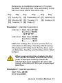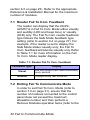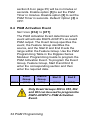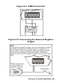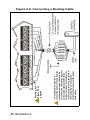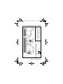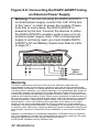
1
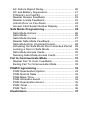
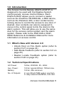
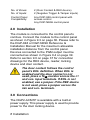
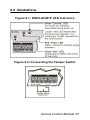
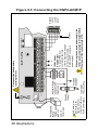
Access Control Module
V2.0
DGP2-ACM1P
Reference & Installation
Manual
Table of Contents
Introduction............................................................ 5
What’s New with Version 2.0.................................. 5
Technical Specifications ......................................... 5
Installation.............................................................. 6
Connections...........................................................
AC Power ...............................................................
Backup Battery .......................................................
Connecting the External Negative Trigger..............
6
7
7
7
About Programming.............................................. 8
Programming ......................................................... 8
Assigning Doors to Partitions ................................. 8
Anti-Tamper Input................................................... 9
Reader’s Red LED to Follow Partition’s Status ...... 9
Reader’s Beep to Follow Partition’s Status .......... 10
Reader’s Green LED Options Upon
Access Granted .................................................... 10
Unlock on Request for Exit (REX) ........................ 11
Door Unlocked Period .......................................... 11
Door Unlocked Period Extension.......................... 11
Relock Interval...................................................... 12
Door Unlocked Schedule...................................... 12
Card Activates Door Unlocked Schedule ............. 14
Door Left Open Access Alarm .............................. 14
Door Left Open Interval Before Access Alarm...... 15
Door Left Open Pre-Alarm.................................... 16
Door Left Open Pre-Alarm Timer.......................... 16
Door Left Open Alarm Feedback.......................... 17
Beep Timer for Door Left Open Alarm.................. 18
Door Forced Open Options .................................. 18
Door Forced Open Alarm Feedback..................... 19
Beep Timer for Door Forced Open Alarm............. 20
Battery Charging Current...................................... 20
AC Failure Report Delay.......................................
AC and Battery Supervision .................................
PIN Entry on PosiPIN ...........................................
Reader Access Feedback ....................................
Reader Locate Feedback .....................................
Unlock Door on Fire Alarm ...................................
Access Card Serial Number Display ....................
20
21
21
22
23
24
24
Safe Mode Programming ....................................
Safe Mode Actions ...............................................
Safe Mode ............................................................
Safe Mode Access................................................
Reader Safe Mode Feedback...............................
Safe Mode Door Unlocked Period ........................
Activating the Safe Mode Door Unlocked Period .
Locking a Door in Safe Mode ...............................
Safe Mode Access Cards .....................................
Deleting Safe Mode Access Cards.......................
25
26
26
27
27
28
28
29
30
31
Fail to Communicate Mode................................. 31
Reader Fail To Com. Feedback ........................... 32
Exiting Fail To Communicate Mode...................... 32
PGM Programming ..............................................
PGM Deactivation Option .....................................
PGM Normal State ...............................................
PGM Base Time ...................................................
PGM Activation Event...........................................
PGM Deactivation Event ......................................
PGM Timer ...........................................................
PGM Test .............................................................
33
33
33
33
34
35
35
36
Illustrations .......................................................... 37
1.0 Introduction
The Access Control Module (DGP2-ACM1P) is
designed to be used with the Digiplex System
control panels’ Access Control feature. Each
DGP2-ACM1P allows you to connect a reader,
such as the PosiProx CR-R880-BL, a REX device,
such as the Paradoor 460, a door contact and a
locking device to control the access to one door. If
desired, door contacts can also be assigned to
zones in the control panel to link the doors to the
alarm system. This will allow you to use the same
door for the access control system and the alarm
system. Please refer to the DGP-848 or DGPNE96 Reference & Installation Manual for more
information on access control.
1.1 What’s New with Version 2.0
• Unlock Door on Fire Alarm option (refer to
section 5.27 on page 24)
• Safe Mode Features (refer to section 6.0 on
page 25)
• Reader Locate Feedback option (refer to
section 5.26 on page 23)
1.2 Technical Specifications
AC Power:
16Vac, 20/40VA, 50 - 60Hz
Aux. Power:
12Vdc, typical 600mA, 700mA max.
Battery:
12Vdc, 4Ah minimum
No. of Outputs:
2; one 50mA PGM output, one form
C relay rated at 5A/28Vdc, N.O./N.C.
Access Control Module 5
No. of Zones:
2 (Door Contact & REX device)
No. of Inputs:
2 (Negative Trigger & Tamper inputs)
Control Panel
Compatibility:
Any DGP-848 control panel with
access control
Any DGP-NE96 control panel
2.0 Installation
The module is connected to the control panel’s
combus. Connect the module to the control panel
as shown in Figure 9.3 on page 38. Please refer to
the DGP-848 or DGP-NE96 Reference &
Installation Manual for the maximum allowable
installation distance from the control panel.
Devices connected to the PGM output must be
connected as shown in Figure 9.4 on page 39.
Refer to section 9.0 on page 37 for connection
drawings for the REX device, reader, locking
device and door contact.
The door contact follows the control
panel’s EOL definition. When EOL is
enabled and the door contact is not
used, place a 1k9 resistor across the CT
and AUX- input terminals. If EOL is not
enabled, use a jumper. If the REX device
is not used, place a jumper across the
REX and AUX- terminals.
3.0 Connections
The DGP2-ACM1P is available with a built-in
power supply. This power supply is used to provide
power to the door locking device.
6 Installation
3.1 AC Power
Use a 16.5Vac (50/60 Hz) transformer with a
minimum 20VA rating to provide sufficient AC
power. Do not use any switch-controlled
outlets to power the transformer. Connect the
transformer as shown in Figure 9.3 on page
38.
3.2 Backup Battery
To supply power to the module’s door lock
relay during a power failure, connect a 12Vdc
4Ah rechargeable acid/lead or gell cell backup
battery as shown in Figure 9.3 on page 38.
Connect the battery after applying AC power.
When installing the battery, verify
proper polarity as reversed
connections will blow the battery fuse.
3.3 Connecting the External Negative
Trigger
The DGP2-ACM1P comes supplied with an
external negative trigger. You can use a PGM
from the control panel or another module to
release the access control door lock. Connect
the desired PGM output terminal to the “TRIG
(-)” terminal of the module as shown in Figure
9.5 on page 39. Once connected, program the
desired PGM event. When the event occurs,
the door will unlock. The external negative
trigger can also be triggered using a pushbutton. When the push button is pressed, the
Access Control Module 7
door will unlock. Connect the push-button as
shown in Figure 9.5 on page 39.
4.0 About Programming
How to program.
1. Press and hold the [0] key.
2. Enter the [INSTALLER CODE].
3. Enter section [953] (DGP-848) or [4003]
(DGP-NE96).
4. Enter the DGP2-ACM1P’s 8-digit [SERIAL
NUMBER].
5. Enter the 3-digit [SECTION] you want to
program.
6. Enter the required data.
The DGP2-ACM1P can also be programmed using
the WinLoad software (V2.0 or higher) or using the
control panel’s Module Broadcast feature. Refer to
the control panel’s Reference & Installation Manual
for more details. Please note that the serial number
can be located on the Access Control Module’s PC
board.
5.0 Programming
5.1 Assigning Doors to Partitions
SECTION [001]: OPTIONS [1] TO [8]
8 About Programming
The access control door can be assigned to
one or more partitions in the alarm system.
This means that the actions performed with
the access card will be directly linked to the
partition(s) assigned to that door. To assign an
access control door to a partition, simply
enable the option that corresponds to the
desired partition. Options [1] to [8] represent
partitions 1 to 8 respectively. Partition 1 is
enabled by default.
The Access Control Module can
only be assigned to partitions 5 to 8
if connected to a DGP-NE96 control
panel.
5.2 Anti-Tamper Input
SECTION [002]: OPTION [1]
The DGP2-ACM1P does not come equipped
with an anti-tamper switch. If required, enable
option [1] and connect an anti-tamper switch
to the “TMP” input as shown in Figure 9.2 on
page 37. When a tamper is detected on the
module, it will send a tamper report to the
control panel via the bus. Default: Option [1]
OFF.
5.3 Reader’s Red LED to Follow Partition’s
Status
SECTION [002]: OPTION[3]
The reader’s red LED can be programmed to
flash according to the partition’s status. When
Access Control Module 9
this feature is enabled, the reader’s red LED
will flash when the partition is arming, in Exit
Delay, in Entry Delay, in Burglar Alarm or in
Fire Alarm. Default: Option [3] is ON.
5.4 Reader’s Beep to Follow Partition’s
Status
SECTION [002]: OPTION [4]
This feature will only function when the
Reader’s Red LED to Follow Partition’s Status
feature is enabled (refer to section 5.3 on
page 9). The reader can be programmed to
beep according to the partition’s status. When
this feature is enabled, the reader will beep
when the partition is arming, in Exit Delay, in
Entry Delay, in Burglar Alarm or in Fire Alarm.
Default: Option [4] is ON.
5.5 Reader’s Green LED Options Upon
Access Granted
SECTION [002]: OPTION [7]
With option [7] ON, the reader’s green LED
will illuminate when the door is unlocked,
except if the door is in Safe Mode (refer to
section 6.0 on page 25). With option [7] OFF,
the reader’s green LED will not illuminate
when the door is unlocked. Default: Option [7]
is ON.
10 Programming
5.6 Unlock on Request for Exit (REX)
SECTION [002]: OPTION [8]
When the REX device detects movement, it
can permit passage with or without turning the
door handle. If this option is enabled, the door
is unlocked when the REX device detects
movement and users on either side of the
door will be able to open the door. If this
option is disabled, the door will unlock once
the handle is turned only on the REX device’s
side. Default: Option [8] is OFF.
5.7 Door Unlocked Period
SECTION [006]
The Door Unlocked Period is the period of
time that the door will remain unlatched after
access is granted or after a Request for Exit is
received. Enter any value between 001 and
255 seconds. Default: 005 seconds.
5.8 Door Unlocked Period Extension
SECTION [007]
The Door Unlocked Period Extension is the
amount of time added to the Door Unlocked
Period (refer to section 5.7 on page 11), which
leaves the door unlatched longer. This will
allow those with this feature enabled in their
User Code Options extra time to enter, which
may be useful for the physically challenged or
for seniors. Enter any value between 001 and
255 seconds. Default: 015 seconds.
Access Control Module 11
5.9 Relock Interval
SECTION [002]: OPTION [6]
The locking device will remain unlatched
during the Door Unlocked Period (refer to
section 5.7 on page 11), but once the door is
opened it can be programmed to latch as
soon as the door closes or latch immediately
even if the door has not closed. When the
option is ON, the locking device will latch
when the door closes. When the option is
OFF, the locking device will latch immediately.
Default: Option [6] is OFF.
5.10Door Unlocked Schedule
SECTION [013]
The Door Unlocked Schedule determines the
hours, days, and holidays that the door will
remain unlocked. Therefore, users will not
have to present their access cards to the
reader in order to gain access to an access
control door. The Door Unlocked Schedule will
continue to function even when the door is in
Safe Mode (refer to section 6.0 on page 25),
unless the Safe Mode Door Unlocked Period
is activated (refer to section 6.6 on page 28).
The schedule consists of two programmable
time periods called Intervals that determine
the time of day and which days the users will
be granted access. When a schedule is
programmed with “H”, users will have access
during the holidays programmed in the control
panel (refer to the DGP-848 or DGP-NE96
12 Programming
Reference & Installation Manual). Program
the Start Time and End Time according to the
24-hour clock within the same day.
Key
Day
[1] Sunday (S)
Key
Day
Key
Day
[4] Wednesday (W) [7] Saturday (S)
[2] Monday (M) [5] Thursday (T)
[8] Holidays (H)
[3] Tuesday (T) [6] Friday (F)
Example 1: (standard operation)
Interval 1: Start Time 07:00
End Time 16:00
_MTWTF__
Interval 2: Start Time 10:00
End Time 17:00
S_____SH
With this setting, the access control door is
unlocked on Monday, Tuesday, Wednesday,
Thursday and Friday from 7am to 4pm, and
on Saturday, Sunday and Holidays from 10am
to 5pm.
When programming the schedule, the End
Time can be set earlier than the Start Time
(refer to Example 2 below). Please be
advised that once unlocked, the door will
remain unlocked until the next programmed
End Time.
Example 2: (special operation)
Start Time 22:00
End Time 8:00
Access Control Module 13
With this setting, the access control door is
locked between 8am and 10pm, and unlocked
from 10pm to 11:59pm and from 12:00am to
8am on the selected day(s).
5.11 Card Activates Door Unlocked Schedule
SECTION [002]: OPTION [5]
When the Door Unlocked Schedule is
programmed (refer to section 5.10 on page
12) and this option is enabled, the door is
locked until the first valid access card is
presented. Once the door is unlocked, it will
remain unlocked until the end of the schedule.
For example: the schedule is 7AM to 5PM
Monday to Friday, option [5] is enabled, and a
valid access card is presented to the reader at
8AM on Monday. Although the schedule
started at 7AM, the door remained locked
from 7AM to 8AM. Once access was granted
at 8AM, the door remained unlocked until
5PM. Default: Option [5] is OFF.
5.12Door Left Open Access Alarm
SECTION [003]: OPTION [1]
With option [1] ON, when an access control
door is opened after an Access Granted or a
Request for Exit, a local access alarm will
14 Programming
generate if the door is not closed within a
certain period of time (refer to section 5.13 on
page 15). Default: Option [1] is OFF.
When the Door Left Open Alarm is disabled,
the following sections are also disabled:
Section
[003] Option [2] Door Left Open Pre-alarm
Option [3] Door Left Open Alarm (audible/silent)
Option [4] Door Left Open Alarm follows
(restore/timer)
[008] Door Left Open Interval Before Access Alarm
[009] Door Left Open Pre-alarm Timer
[010] Beep timer for Door Left Open Alarm
5.13Door Left Open Interval Before Access
Alarm
SECTION [008]
The Door Left Open Interval is the period of
time that a door can remain open after an
Access Granted or a Request for Exit without
generating a local access alarm (refer to
section 5.12 on page 14). Enter any value
between 001 and 255 to determine the
number of seconds the door may remain open
before the local access alarm is triggered.
Default: 060 secs.
The value programmed in this
section must be higher than that
programmed for the Door Left Open
Pre-Alarm Timer (refer to section
5.15 on page 16).
Access Control Module 15
5.14Door Left Open Pre-Alarm
SECTION [003]: OPTION [2]
An access control door is programmed with a
Door Left Open Interval (refer to section 5.13
on page 15). The pre-alarm will cause the
reader to beep for a programmed period of
time (refer to section 5.15 on page 16) before
the end of the Door Left Open Interval to alert
users that the access control door was left
open and will generate a local access alarm
(refer to section 5.12 on page 14) if it is not
closed. The pre-alarm beeps slower than the
Door Left Open alarm (about twice every
second). With option [2] ON, the Door Left
Open Pre-alarm feature is enabled. Default:
Option [2] is ON.
5.15Door Left Open Pre-Alarm Timer
SECTION [009]
This feature determines the amount of time
prior to the end of the Door Left Open Interval
(refer to section 5.13 on page 15) that the
Door Left Open Pre-Alarm will activate (refer
to section 5.14 on page 16). For example, if
the Door Left Open Pre-Alarm is set at 15
seconds, the reader will start beeping 15
seconds before the end of the Door Left Open
Interval. Enter any value between 001 and
255 seconds. Default: 015 secs.
16 Programming
The value programmed in this
section must be lower than that
programmed for the Door Left Open
Interval (refer to section 5.13 on
page 15).
5.16Door Left Open Alarm Feedback
SECTION [003]: OPTIONS [3] AND [4]
An access control door is programmed with a
Door Left Open Interval (refer to section 5.13
on page 15). Once this interval has expired,
the Door Left Open Alarm can be either
audible or silent and will either beep as long
as the local access alarm is occurring or
follow the beep timer in section [010] (refer to
section 5.17 on page 18). The sound of the
Door Left Open Alarm resembles the rapid
beep generated during the last ten seconds of
the Exit Delay. When the door is closed during
a local access alarm, the Door Left Open
Restore event can be logged in the panel’s
Event Buffer (refer to DGP-848 or DGP-NE96
Reference & Installation Manual). With option
Access Control Module 17
[3] ON, the alarm will be audible. With option
[4] ON, the Door Left Open Alarm is set to
follow the beep timer programmed in section
[010]. With option [4] OFF, the Door Left Open
Alarm is set to beep as long as the alarm is
occurring. Default: Option [3] is ON and
option [4] is OFF.
5.17Beep Timer for Door Left Open Alarm
SECTION [010]
With section [003] option [4] ON (refer to
section 5.16 on page 17), this beep timer
determines the amount of time the Door Left
Open Alarm will beep. Once the Door Left
Open Interval (refer to section 5.13 on page
15) has expired, the Door Left Open Alarm
(refer to section 5.12 on page 14) will be
triggered. Enter any value between 001 and
255 to determine the number of seconds the
local access alarm will beep. Default: 005
seconds.
5.18Door Forced Open Options
SECTION [003]: OPTION [5]
If an access control door is opened without an
access card, an external trigger or receiving a
Request for Exit, an access alarm can be
generated. A Burglar Alarm can also be
generated (refer to the DGP-848 or DGPNE96 Reference & Installation Manual). When
the door is closed during an access alarm, the
Door Forced Open Restore event can be
18 Programming
logged in the panel’s Event Buffer (refer to
DGP-848 or DGP-NE96 Reference &
Installation Manual). Enabling the option will
enable the Door Forced Open Alarm. Default:
Option [5] is OFF.
When the Door Forced Open Alarm is
disabled, the following sections are also
disabled:
Section
[003] Option [6] Door Forced Open Alarm (audible/
silent)
Option [7] Door Left Open Alarm Follows
(restore/timer)
[011] Beep timer for Door Forced Open Alarm
5.19Door Forced Open Alarm Feedback
SECTION [003]: OPTIONS [6] AND [7]
The Door Forced Open alarm can be either
audible or silent and will either beep as long
as the Door Forced Open alarm is occurring
or follow the beep timer in section [011] (refer
to section 5.20 on page 20). The sound of the
Door Forced Open Alarm resembles the rapid
beep generated during the last ten seconds of
the Exit Delay. Enabling option [6] will make
the alarm audible. Enabling option [7] sets the
Door Forced Open Alarm to follow the beep
timer programmed in section [011]. Disabling
option [7] sets the Door Forced Open Alarm to
beep as long as the alarm is occurring.
Default: Option [6] is ON and option [7] is
OFF.
Access Control Module 19
5.20Beep Timer for Door Forced Open Alarm
SECTION [011]
This beep timer determines the amount of
time the Door Forced Open Alarm (refer to
section 5.18 on page 18) will beep. Enter any
value between 001 and 255 to determine the
number of seconds the Door Forced Open
Alarm will beep. Default: 005 seconds.
5.21Battery Charging Current
SECTION [002]: OPTION [2]
With this feature OFF, the battery charging
current will be 350mA. With this feature ON,
the battery charging current will be 700mA.
Setting the charging current at 350mA will
take longer to recharge the battery than at
700mA, but will consume less power from the
module itself. Default: Option [2] is OFF.
5.22AC Failure Report Delay
SECTION [005]
The value programmed in this section
represents how long the Access Control
Module will wait before reporting an AC power
failure to the control panel. To program the
timer, enter any value between 001 to 255
minutes or 000 for instant reporting into
section [005]. Default: 000 (Instant Report).
20 Programming
5.23AC and Battery Supervision
SECTION [004]: OPTION [8]
This feature applies to DGP2-ACM1P version
1.1 or higher. Enable this feature if the DGP2ACM1P’s power supply is not being used.
This disables AC and battery power
supervision and prevents a trouble from being
generated. Default: Option [8] is OFF.
5.24PIN Entry on PosiPIN
SECTION [004]: OPTION [5]
This feature pertains to the Card and Code
Access option programmed in the DGP-NE96
control panel (refer to the Access Control
section of the DGP-NE96 Reference &
Installation Manual). With the Card and Code
Access option ON, a user must present their
access card to the reader and then enter their
PIN to enter an armed or locked access
control door. If the reader is connected to a
DGP2-ACM1P and if there is no keypad
nearby in which to enter a PIN, access will be
denied. With section [004] option [5] ON and
by installing a PosiPIN (CR-R885-BL), the
user can present their card to the PosiPIN
reader and then enter their PIN on the
PosiPIN’s keypad to acquire access. Default:
Option [5] is OFF.
Access Control Module 21
This feature can only be used with
DGP-NE96 control panels. If the access
control door is using an ordinary
proximity reader and is connected to
the DGP2-ACM1P, disable the door’s
Card and Code Access option in the
DGP-NE96 panel.
5.25Reader Access Feedback
SECTION [003]: OPTION [8]
This feature determines how the reader will
communicate Access Granted and Access
Denied events. If option [8] is ON, the
reader’s feedback is both visual and audible
(LED and beep tone). If option [8] is OFF, the
reader’s feedback is visual (LED) only. Refer
to Table 5.1 for more information on the
Access reader display. Default: Option [8] is
OFF.
The reader’s access granted green LED
must be enabled (refer to section 5.5 on
page 10) in order for the green LED to
illuminate when an access granted
event occurs.
Table 5.1: Reader Access Feedback
Option [8]
ON
OFF
Access Granted
Access Denied
Green LED
illuminates and
confirmation beep
sounds (“Beep-BeepBeep-Beep-Beep”)
Green LED
illuminates
Red LED flashes and
rejection beep
sounds (“Beeeeep”)
22 Programming
Red LED flashes
5.26Reader Locate Feedback
SECTION [004]: OPTION [6]
This feature applies to DGP2-ACM1P version
2.0 or higher and determines how the reader
will communicate a Locate request from the
control panel. When option [6] is enabled, the
reader will convey the status both visually and
audibly (LED and beep tone). When option [6]
is disabled, the status will be communicated
visually (LED) only. Refer to Table 5.2 on
page 23 for more information on the Locate
reader display. Default: Option [6] is OFF.
If the locate request is not stopped
manually (refer to the DGP-848 or DGPNE96 Reference & Installation Manual),
the DGP2-ACM1P will automatically stop
the Locate request after 30 minutes.
Table 5.2: Reader Locate Feedback
Feedback Type
Display
Visual
Green LED flashes quickly
Audible
1 beep every two seconds
Access Control Module 23
5.27Unlock Door on Fire Alarm
SECTION [004]: OPTION [7]
This feature applies to DGP2-ACM1P version
2.0 or higher and determines if the access
control door connected to the DGP2-ACM1P
will unlock automatically during a fire alarm.
When option [7] is enabled, the door will
unlock during a fire alarm. When option [7] is
disabled, the door will not unlock
automatically during a fire alarm. Default:
Option [7] is OFF.
If the Unlock Door on Fire Alarm feature
is enabled, and a fire alarm occurs and
then the door goes into Safe Mode
(refer to section 6.0 on page 25), the
door will remain unlocked until a valid
Safe Mode access card (refer to section
6.8 on page 30) is presented to the
reader three times.
5.28Access Card Serial Number Display
SECTION [040]
This feature applies to DGP2-ACM1P version
1.02 or higher and allows you to view an
access card’s serial number. Using an LCD or
Grafica keypad, enter the DGP2-ACM1P’s
programming mode and then enter section
[040]. Present the desired access card(s) to
the reader connected to the DGP2-ACM1P.
The access card’s serial number will be
displayed on the keypad’s LCD screen. In this
24 Programming
mode, the door connected to the module
cannot be accessed.
6.0 Safe Mode Programming
The Safe Mode feature applies to DGP2ACM1P version 2.0 or higher.
When a communication loss occurs between the
DGP2-ACM1P and the control panel, and lasts
longer than 30 seconds, the DGP2-ACM1P enters
into Safe Mode if the feature is enabled (refer to
section 6.2 on page 26). When in Safe Mode, the
access control door that is connected to the
affected DGP2-ACM1P will grant access to
designated access cards only (refer to section 6.8
on page 30). In Safe Mode, the access control
door’s Unlocked Schedule (refer to section 5.10 on
page 12) will continue to function, however the
reader will display the Safe Mode status (refer to
section 6.4 on page 27) only. If you wish to override
the door’s Unlocked Schedule while in Safe Mode,
activate the Safe Mode Door Unlocked Period
(refer to section 6.6 on page 28). The DGP2ACM1P will exit Safe Mode once communication
has been restored between the DGP2-ACM1P and
the control panel.
If a communication failure occurs between
the DGP2-ACM1P and the control panel
because the number of allowable modules
has been exceeded, the DGP2-ACM1P will
enter Fail To Com. Mode (refer to section 7.0
on page 31) instead of Safe Mode.
Access Control Module 25
6.1 Safe Mode Actions
The following table lists the possible actions
that can be performed while in Safe Mode.
Table 6.1: Safe Mode Actions
Safe Mode Action
How To
Present a Safe Mode access card
Access Granted
to the reader three times*
Enter the appropriate section and
Program Safe Mode then present the access card to
the DGP2-ACM1P’s reader three
Access Cards
times*
Present a Safe Mode access card
Activate Safe Mode to the reader five times: three
Door Unlocked
times* (access granted) and then
two more times within ten
Period
seconds
Ensure that the Safe Mode Door
Unlocked Period is activated, and
Lock a Door in Safe then present a Safe Mode access
card to the reader five times:
Mode
three times* (access granted) and
then two more times within ten
seconds
*After presenting the access card to the reader the first
time, you have ten seconds to present the card a second
time and then another ten seconds to present it the third
time. If either of the ten second intervals are exceeded, the
counter is reset and an access denied event is generated.
6.2 Safe Mode
SECTION [022]: OPTION [1]
This option enables or disables the Safe
Mode feature (refer to section 6.0 on page
26 Safe Mode Programming
25). Enable option [1] to enable the Safe
Mode feature. Default: Option [1] is ON.
6.3 Safe Mode Access
SECTION [022]: OPTION [2]
When option [2] is enabled, the access cards
that were programmed as being valid during
Safe Mode (refer to section 6.8 on page 30)
can be used to gain access to the access
control door. When option [2] is disabled, no
one will be able to gain access to the access
control door during Safe Mode. Default:
Option [2] is ON.
6.4 Reader Safe Mode Feedback
SECTION [022]: OPTION [3]
This feature determines how the reader will
communicate that the DGP2-ACM1P it is
connected to is in Safe Mode. When option [3]
is enabled, the reader will convey the status
both visually and audibly (LED and beep
tone). When option [3] is disabled, the status
will be communicated visually (LED) only.
Refer to Table 6.2 for more information on the
Safe Mode reader display. Default: Option [3]
is OFF.
When in Safe Mode, the reader will
display the Safe Mode status (refer to
Table 6.2) only. Therefore, if the door is
unlocked, the reader will not display
the access granted status.
Access Control Module 27
Table 6.2: Reader Safe Mode Feedback
Feedback Type
Display
Visual
Red and Green LED flash alternately
(LED off in between)
Audible
2 beeps every two seconds
6.5 Safe Mode Door Unlocked Period
SECTION [023]
When the DGP2-ACM1P is in Safe Mode, you
can force the access control door to remain
unlocked (refer to section 6.6 on page 28) for
the time period programmed in section [023].
Enter a value between 001 and 024 hours, or
enter 000 to disable the Safe Mode Door
Unlocked Period feature. When in Safe Mode,
if the Safe Mode Door Unlocked Period is
disabled (000), an unlocked door will remain
unlocked until it is locked manually (refer to
section 6.7 on page 29) Default: 000.
6.6 Activating the Safe Mode Door Unlocked
Period
When DGP2-ACM1P goes into Safe Mode
(refer to section 6.0 on page 25), the Safe
Mode Door Unlocked Period (refer to section
6.5 on page 28) is activated when a valid Safe
Mode access card (refer to section 6.8 on
page 30) is presented to the door’s reader five
times: three times (access granted) and then
two more times within ten seconds. When
activated, the Safe Mode Door Unlocked
28 Safe Mode Programming
Period overrides the door’s Unlocked
Schedule (refer to section 5.10 on page 12)
and the door will remain unlocked until the
end of the Safe Mode Door Unlocked Period
or until it is locked manually (refer to section
6.7 on page 29).
When in Safe Mode, the reader will
display the Safe Mode status (refer to
Table 6.2) only. Therefore, the reader
will not display an unlocked status
(refer to section 5.25 on page 22) even
if the door is unlocked.
6.7 Locking a Door in Safe Mode
To lock an access control door that is in Safe
Mode, ensure that the Safe Mode Door
Unlocked Period is activated (refer to section
6.6 on page 28) and then present a valid Safe
Mode access card (refer to section 6.8 on
page 30) to the door’s reader five times: three
times (access granted) and then two more
times within ten seconds. Locking a door in
Safe Mode overrides the door’s Unlocked
Schedule (refer to section 5.10 on page 12)
and Safe Mode Door Unlocked Period (refer
to section 6.5 on page 28). Therefore, the
door will remain locked until a valid Safe Mode
access card is presented to the reader three
times (access granted).
Access Control Module 29
6.8 Safe Mode Access Cards
SECTIONS [061] TO [064]
When the DGP2-ACM1P enters Safe Mode
(refer to section 6.0 on page 25), only
designated access cards can be used to gain
access to the access control door. You can
program up to four access cards as being
valid during Safe Mode. Sections [061] to
[064] correspond to Safe Mode access cards
1 to 4 respectively.
The Safe Mode Access feature (refer to
section 6.3 on page 27) must be
enabled for the Safe Mode access
cards to function.
How to program Safe Mode Access Cards.
In step 5 in section 4.0 on page 8:
1. Enter a section number between [061] and
[064].
2. Present the access card to the reader that is
connected to the DGP2-ACM1P three times.
Note: After presenting the access card to the reader
the first time, you have ten seconds to present the
card a second time and then another ten seconds to
present it the third time. If either of the ten second
intervals are exceeded, the card-passed counter is
reset and an access denied event is generated.
30 Safe Mode Programming
6.9 Deleting Safe Mode Access Cards
SECTIONS [070] TO [074]
Programmed Safe Mode access cards (refer
to section 6.8 on page 30) are deleted in
sections [070] to [074]. Enter the appropriate
section to delete the corresponding access
card (refer to Table 6.3 on page 31). If the
access card is deleted successfully, the
keypad that you are programming with will
activate a confirmation beep (“BEEP-BEEPBEEP-BEEP-BEEP”). A rejection beep
(“BEEEEEEEEEEEEP”) will sound if the access
card was not deleted successfully.
Table 6.3: Deleting Safe Mode Access Cards
Section
Access Card
[070]
Delete all programmed access cards
[071]
Delete access card #1 in section [061]
[072]
Delete access card #2 in section [062]
[073]
Delete access card #3 in section [063]
[074]
Delete access card #4 in section [064]
7.0 Fail to Communicate Mode
This feature applies to DGP2-ACM1P version 2.0
or higher. If a communication failure occurs
between the DGP2-ACM1P and the control panel
because the number of allowable modules has
been exceeded, the DGP2-ACM1P will enter Fail
To Com. Mode instead of Safe Mode (refer to
Access Control Module 31
section 6.0 on page 25). Refer to the appropriate
Reference & Installation Manual for the maximum
number of modules.
7.1 Reader Fail To Com. Feedback
The reader can display that the DGP2ACM1P is in Fail To Com. Mode either visually
and audibly (LED and beep tone) or visually
(LED) only. The Fail To Com. reader feedback
type follows the Safe Mode feedback type
setting (refer to section 6.4 on page 27). For
example, if the reader is set to display the
Safe Mode status visually only, the Fail To
Com. feedback will also be visually only. Refer
to Table 7.1 for more information on the Fail
To Com. Mode reader display.
Table 7.1: Reader Fail To Com. Feedback
Feedback Type
Display
Visual
Red and Green LED flash alternately
every second
Audible
2 beeps every two seconds
7.2 Exiting Fail To Communicate Mode
In order to exit Fail To Com. Mode (refer to
section 7.0 on page 31), ensure that the
number of modules connected to the control
panel does not exceed the maximum
allowable number and then perform a
Remove Modules operation twice (refer to the
32 Fail to Communicate Mode
DGP-848 or DGP-NE96 Reference &
Installation Manual).
8.0 PGM Programming
8.1 PGM Deactivation Option
SECTION [004]: OPTION [1]
This option determines whether the PGM will
deactivate after the PGM Timer has elapsed
(refer to section 8.6 on page 35) or after the
Deactivation Event has occurred (refer to
section 8.5 on page 35). Enabling option [1]
sets the PGM to follow the PGM Timer.
Disabling option [1] sets the PGM to follow the
PGM Deactivation Event. Default: Option [1]
is OFF.
8.2 PGM Normal State
SECTION [004]: OPTION [2]
The on-board PGM can be set as Normally
Open or Normally Closed. Enabling option [2]
will set the PGM as a Normally Closed (N.C.)
contact. Disabling option [2] will set the PGM
as a Normally Open (N.O.) contact. Default:
Option [2] is OFF.
8.3 PGM Base Time
SECTION [004]: OPTION [3]
This feature defines whether the value
programmed as the PGM Timer (refer to
Access Control Module 33
section 8.6 on page 35) will be in minutes or
seconds. Enable option [3] to set the PGM
Timer in minutes. Disable option [3] to set the
PGM Timer in seconds. Default: Option [3] is
OFF.
8.4 PGM Activation Event
SECTIONS [014] TO [017]
The PGM Activation Event determines which
event will activate DGP2-ACM1P’s on-board
PGM output. The Event Group specifies the
event, the Feature Group identifies the
source, and the Start # and End # sets the
range within the Feature Group. Use the PGM
Programming Table in the Digiplex Series
Modules’ Programming Guide to program the
PGM Activation Event. To program the Event
Group, Feature Group, Start # and End #,
enter the corresponding section and then
enter the required data.
PGM
Event
Group
Feature
Group
Start #
End #
[014]
[015]
[016]
[017]
Only Event Groups 000 to 055, 062
and 063 can be used to program the
DGP2-ACM1P’s PGM Activation
Event.
34 PGM Programming
8.5 PGM Deactivation Event
SECTIONS [018] TO [021]
If the PGM Deactivation Option is set to follow
the PGM Deactivation Event (refer to section
8.1 on page 33), the PGM will return to its
normal state when the event programmed in
sections [018] to [021] occurs. The Event
Group specifies the event, the Feature Group
identifies the source, and the Start # and End
# sets the range within the Feature Group.
Use the PGM Programming Table in the
Digiplex Series Modules’ Programming Guide
to program the PGM Deactivation Event. To
program the Event Group, Feature Group,
Start # and End #, enter the corresponding
section and then enter the required data.
PGM
Event
Group
Feature
Group
Start #
End #
[018]
[019]
[020]
[021]
Only Event Groups 000 to 055, 062
and 063 can be used to program the
DGP2-ACM1P’s PGM Deactivation
Event.
8.6 PGM Timer
SECTION [012]
If the PGM Output is set to follow its PGM
Timer (refer to section 8.1 on page 33), the
value entered in section [012] represents the
Access Control Module 35
amount of time that the PGM will remain
activated. To program the PGM Timer, enter a
3-digit decimal value from 001 to 255 in
section [012]. Depending on the PGM Base
Time (refer to section 8.3 on page 33), the
PGM Timer will either be in seconds or
minutes. Default: 005.
8.7 PGM Test
SECTION [030]
Entering section [030] will activate the PGM
for 8 seconds to verify if the PGM is
functioning properly.
36 PGM Programming
9.0 Illustrations
Figure 9.1: DGP2-ACM1P LED Indicators
Figure 9.2: Connecting the Tamper Switch
Access Control Module 37
38 Illustrations
Cold water pipe
grounding is not
required when not
using the module’s onboard power supply.
Rechargeable
Battery:
YUASA model
# NP7-12
UL/ULC
12Vdc / 4Ah
Combus
When using the on-board power supply, the
12Vdc power supply output will automatically
shut down if the current exceeds 1.1A.
12Vdc Power
Supply Output
To power REX, door
contact and door lock
(refer to Figure 9.8 on page
42 if you are not using
DGP2-ACM1P’s on-board
power supply).
Disconnect the battery before
replacing the fuse.
Digiplex
series
control
panel
Figure 9.3: Connecting the DGP2-ACM1P
Figure 9.4: PGM Connection
Figure 9.5: Connecting the External Negative
Trigger
Access Control Module 39
40 Illustrations
if a routing cable is required to
connect the reader to the module, the
routing cable must be shielded. Do
not connect the shield wires together
at the reader cable splice.With the
shield wire already terminated at the
reader, simply terminate the shield at
the module. Do not connect the
shield to the black wire at the reader
cable splice.
Warning: See
Figure 9.8 on
page 42.
Figure 9.6: Connecting a Routing Cable
Anode
Cathode
1N4007
Diode
** Door contact
must be
connected to CT
terminal
*** = If the Request for Exit (REX) device is not used,
place a jumper across the AUX- and REX terminals.
** = If the door contact is not used, install a jumper or a
1k9 resistor across the AUX- and CT terminals
depending on the control panel’s EOL definition.
* = Follows control panel’s EOL definition.
*** REX device must be
connected to REX terminal
When connecting the diode to the door lock, be
sure to connect the cathode of the diode to the
positive (+) voltage and the anode to the negative
(-) voltage.
Warning: See Figure
9.8 on page 42.
No EOL required
on REX
DGP2ACM1-EI05.fm Page 41 Monday, July 19, 2004 12:00 PM
Figure 9.7: Connecting Access Control Devices
Access Control Module 41
Figure 9.8: Connecting the DGP2-ACM1P Using
an External Power Supply
Warning: If you are not using the DGP2-ACM1P’s
on-board power supply, connect the “red” of the bus
to the “aux+” in order to power the module. Please
note that in such cases, the DGP2-ACM1P is
powered by the bus. Connect the devices to either
the DGP2-ACM1P’s auxiliary output (aux) or to an
external power supply. Also, if the on-board power
supply is not being used, you must disable DGP2ACM1P’s AC and Battery Supervision feature (refer
to page 21).
Warranty
The Seller warrants its products to be free from defects in materials and
workmanship under normal use for a period of one year. Except as specifically
stated herein, all express or implied warranties whatsoever, statutory or otherwise,
including without limitation, any implied warranty of merchantability and fitness for
a particular purpose, are expressly excluded. Because Seller does not install or
connect the products and because the products may be used in conjunction with
products not manufactured by Seller, Seller cannot guarantee the performance of
the security system. Seller obligation and liability under this warranty is expressly
limited to repairing or replacing, at Seller's option, any product not meeting the
specifications. In no event shall the Seller be liable to the buyer or any other
person for any loss or damages whether direct or indirect or consequential or
incidental, including without limitation, any damages for lost profits, stolen goods,
or claims by any other party, caused by defective goods or otherwise arising from
the improper, incorrect or otherwise faulty installation or use of the merchandise
sold.
Digiplex is a trademarks or registered trademarks of Paradox Security Systems
Ltd. or its affiliates in Canada, the United States and/or other countries. All rights
reserved. Specifications may change without prior notice.
© 2003-2004 Paradox Security Systems Ltd.
42 Illustrations
Printed in Canada - 07/2004
DGP2ACM1-EI05