1
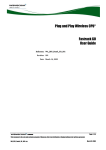
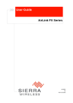
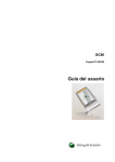
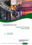
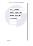
 Plug and Play Wireless CPU®
Fastrack GO User Guide
WM_M&T_Fastrk_UGD_001
002
August 4, 2009
Fastrack GO User Guide
Important Notice
Due to the nature of wireless communications, transmission and reception of data can never be guaranteed. Data may be delayed, corrupted (i.e., have errors) or be totally lost. Although significant delays or losses of data are rare when wireless devices such as the Sierra Wireless modem are used in a normal manner with a well‐constructed network, the Sierra Wireless modem should not be used in situations where failure to transmit or receive data could result in damage of any kind to the user or any other party, including but not limited to personal injury, death, or loss of property. Sierra Wireless accepts no responsibility for damages of any kind resulting from delays or errors in data transmitted or received using the Sierra Wireless modem, or for failure of the Sierra Wireless modem to transmit or receive such data. Safety and Hazards
Do not operate the Sierra Wireless modem in areas where blasting is in progress, where explosive atmospheres may be present, near medical equipment, near life support equipment, or any equipment which may be susceptible to any form of radio interference. In such areas, the Sierra Wireless modem MUST BE POWERED OFF. The Sierra Wireless modem can transmit signals that could interfere with this equipment. Do not operate the Sierra Wireless modem in any aircraft, whether the aircraft is on the ground or in flight. In aircraft, the Sierra Wireless modem MUST BE
POWERED OFF. When operating, the Sierra Wireless modem can transmit signals that could interfere with various onboard systems. Note:
Some airlines may permit the use of cellular phones while the aircraft is on the ground and the door is
open. Sierra Wireless modems may be used at this time.
The driver or operator of any vehicle should not operate the Sierra Wireless modem while in control of a vehicle. Doing so will detract from the driver or operator’s control and operation of that vehicle. In some states and provinces, operating such communications devices while in control of a vehicle is an offence. WM_M&T_Fastrk_UGD_001
Rev 002
Page 2 of 40
Fastrack GO User Guide
Limitations of Liability
This manual is provided “as is”. Sierra Wireless makes no warranties of any kind, either expressed or implied, including any implied warranties of merchantability, fitness for a particular purpose, or noninfringement. The recipient of the manual shall endorse all risks arising from its use. The information in this manual is subject to change without notice and does not represent a commitment on the part of Sierra Wireless. SIERRA WIRELESS AND ITS AFFILIATES SPECIFICALLY DISCLAIM LIABILITY FOR ANY AND ALL DIRECT, INDIRECT, SPECIAL, GENERAL, INCIDENTAL, CONSEQUENTIAL, PUNITIVE OR EXEMPLARY DAMAGES INCLUDING, BUT NOT LIMITED TO, LOSS OF PROFITS OR REVENUE OR ANTICIPATED PROFITS OR REVENUE ARISING OUT OF THE USE OR INABILITY TO USE ANY SIERRA WIRELESS PRODUCT, EVEN IF SIERRA WIRELESS AND/OR ITS AFFILIATES HAS BEEN ADVISED OF THE POSSIBILITY OF SUCH DAMAGES OR THEY ARE FORESEEABLE OR FOR CLAIMS BY ANY THIRD PARTY. Notwithstanding the foregoing, in no event shall Sierra Wireless and/or its affiliates aggregate liability arising under or in connection with the Sierra Wireless product, regardless of the number of events, occurrences, or claims giving rise to liability, be in excess of the price paid by the purchaser for the Sierra Wireless product. Copyright
© 2009 Sierra Wireless. All rights reserved. Trademarks
AirCard® and “Heart of the Wireless Machine®” are filed or registered trademarks of Sierra Wireless. Watcher® is a trademark of Sierra Wireless, registered in the European Community. Sierra Wireless, the Sierra Wireless logo, the red wave design, and the red‐tipped antenna are trademarks of Sierra Wireless. , , ®, inSIM®, “YOU MAKE IT, WE MAKE IT WIRELESS®”, WAVECOM®, WISMO®, Wireless Microprocessor®, Wireless CPU®, Open AT® are filed or registered trademarks of Wavecom S.A. in France and/or in other countries. Windows® is a registered trademark of Microsoft Corporation. QUALCOMM® is a registered trademark of QUALCOMM Incorporated. Used under license. Other trademarks are the property of the respective owners. WM_M&T_Fastrk_UGD_001
Rev 002
Page 3 of 40
Fastrack GO User Guide
Contact Information
Sales Desk:
Post:
Fax:
Web:
Phone:
1-604-232-1488
Hours:
8:00 AM to 5:00 PM Pacific Time
E-mail:
[email protected]
Sierra Wireless
13811 Wireless Way
Richmond, BC
Canada
V6V 3A4
1-604-231-1109
www.sierrawireless.com
Consult our website for up‐to‐date product descriptions, documentation, application notes, firmware upgrades, troubleshooting tips, and press releases: www.sierrawireless.com
Document History
Revision
Date
Document history
001
March 16, 2009
Creation
002
August 4, 2009
Figure revision, table completion
WM_M&T_Fastrk_UGD_001
Rev 002
Page 4 of 40
Fastrack GO User Guide
Contents
1. OVERVIEW .................................................................................................................... 9
RoHS Directive........................................................................................................................................9
2. PACKAGING ............................................................................................................... 11
Contents of Fastrack Go version RS232 and USB .........................................................................11
Packaging Box ......................................................................................................................................12
Product customization.........................................................................................................................13
Product labeling....................................................................................................................................13
3. GENERAL DESCRIPTION ....................................................................................... 14
Fastrack GO versions RS232 ..............................................................................................................14
Fastrack GO version USB ...................................................................................................................15
4. FEATURES AND SERVICES................................................................................... 16
5. USING THE FASTRACK GO................................................................................... 17
Getting Started ......................................................................................................................................17
Mount the Fastrack GO ...................................................................................................................17
Insert/extract the SIM card to/from the Fastrack GO..................................................................17
Set up the Fastrack GO ...................................................................................................................17
Activating USB communication (for Fastrack GO version USB only) ......................................18
Set up serial communication software .........................................................................................20
Verify the Fastrack GO Network Registration ..............................................................................21
Configuring Modem on PC.............................................................................................................22
Creating a New Network Connection on PC ................................................................................25
Making a GPRS Connection...........................................................................................................29
Fastrack GO Operational Status........................................................................................................31
6. TECHNICAL CHARACTERISTICS ....................................................................... 32
Mechanical Characteristics ................................................................................................................32
Electrical Characteristics ....................................................................................................................33
Power Supply (For Fastrack GO version RS232 only) .................................................................33
SIM Interface ....................................................................................................................................33
RS232 Serial interface (For Fastrack GO version RS232 only)...................................................33
USB interface (For Fastrack GO version USB only) ....................................................................34
Frequency Ranges ...........................................................................................................................35
RF Performances .............................................................................................................................35
External Antenna .............................................................................................................................36
Environmental Characteristics...........................................................................................................36
WM_M&T_Fastrk_UGD_001
Rev 002
Page 5 of 40
Fastrack GO User Guide
Function Status Classification .......................................................................................................36
Conformity..............................................................................................................................................37
7. SAFETY RECOMMENDATIONS............................................................................ 38
General Safety .......................................................................................................................................38
Vehicle Safety .......................................................................................................................................39
Care and Maintenance .........................................................................................................................39
Your Responsibility..............................................................................................................................39
8. ONLINE SUPPORT ................................................................................................... 40
WM_M&T_Fastrk_UGD_001
Rev 002
Page 6 of 40
Fastrack GO User Guide
List of Figures
Figure 1.
Complete package contents ................................................................................................. 11
Figure 2.
Packaging Labels for Fastrack GO....................................................................................... 12
Figure 3.
Top casing ............................................................................................................................... 13
Figure 4.
Production Label .................................................................................................................... 13
Figure 5.
Fastrack GO version RS232 general vciew.......................................................................... 14
Figure 6.
Fastrack GO version USB general view ............................................................................... 15
Figure 7.
Procedure for SIM card insertion ......................................................................................... 17
Figure 8.
Dimensioning diagram .......................................................................................................... 32
Figure 9.
DB9 Female connector .......................................................................................................... 34
WM_M&T_Fastrk_UGD_001
Rev 002
Page 7 of 40
Fastrack GO User Guide
List of Tables
Table 1.
Basic features of the Fastrack GO........................................................................................ 16
Table 2.
Fastrack GO operational status ............................................................................................ 31
Table 3.
Mechanical characteristics ................................................................................................... 32
Table 4.
Input characteristics .............................................................................................................. 33
Table 5.
Output characteristics ........................................................................................................... 33
Table 6.
SIM card characteristics........................................................................................................ 33
Table 7.
DB9 pin description................................................................................................................ 34
Table 8.
Frequency ranges ................................................................................................................... 35
Table 9.
Receiver RF performances .................................................................................................... 35
Table 10.
Transmitter RF performances............................................................................................... 35
Table 11.
External antenna characteristics.......................................................................................... 36
Table 12.
Ranges of temperature .......................................................................................................... 36
Table 13.
Standards Conformity List .................................................................................................... 37
WM_M&T_Fastrk_UGD_001
Rev 002
Page 8 of 40
Fastrack GO User Guide
1. Overview
Fastrack GO is a cellular Plug & Play Wireless CPU® offering state‐of‐the‐art GSM/GPRS connectivity for machine to machine applications. Thanks to Fastrack GO, you can connect your wired or disconnected devices together to transfer collect data or control your equipment remotely. . Fastrack GO with its stylish, ergonomic and attractive design comes in two different connecting interfaces RS232 and USB. Fully certified, the quad band 850/900/1800/1900 MHz Fastrack GO offers GPRS Class 10 capability. Fastrack GO is controlled by firmware through a set of AT commands. Fastrack GO is suitable for wide voltage range and low power consumption type of applications. Fastrack GO offers the easiest integration and upgrading and above all the quickest time to market: turn on the power and off you go! This document describes the Fastrack GO and gives information on the following topics : •
general information, •
functional description, •
basic services available, •
technical characteristics, •
installing and using the Fastrack GO, •
user‐level troubleshooting, •
Recommended accessories to be used with the product. RoHS Directive
The Fastrack GO is compliant with RoHS Directive 2002/95/EC, which sets limits for the use of certain restricted hazardous substances. This directive states that ʺfrom 1st July 2006, new electrical and electronic equipment put on the market does not contain lead, mercury, cadmium, hexavalent chromium, polybrominated biphenyls (PBB), and polybrominated diphenyl ethers (PBDE)ʺ. Plug & Plays which are compliant with this directive are identified by the RoHS logo
on their label.
WM_M&T_Fastrk_UGD_001
Rev 002
Page 9 of 40
Fastrack GO User Guide
Disposing of the product
This electronic product is subject to the EU Directive 2002/96/EC for Waste
Electrical and Electronic Equipment (WEEE). As such, this product must not be
disposed off at a municipal waste collection point. Please refer to local regulations
for directions on how to dispose off this product in an environmental friendly
manner.
WM_M&T_Fastrk_UGD_001
Rev 002
Page 10 of 40
Fastrack GO User Guide
2. Packaging
Contents of Fastrack Go version RS232 and USB
The complete package content of the Fastrack GO version RS232 or Fastrack Go USB consists of (see): •
one packaging box (A), •
one Fastrack GO (B), •
one Antenna (C), •
one power supply (only for Fastrack Go RS232)(D) B
D
C
A
B
Figure 1. Complete package contents
WM_M&T_Fastrk_UGD_001
Rev 002
Page 11 of 40
Fastrack GO User Guide
Packaging Box
The packaging box is a carton box (see) with the following external dimensions: •
width: 55mm •
height: 70mm •
length: 160mm A packaging label is slicked on the packaging box cover and supports the: •
WAVECOM logo •
Product reference (Fastrack GO) •
IMEI code •
MSN code •
ICCID code (when requested) •
Bar code (bundling the 3 codes) •
Serial number •
CE and WEE logos •
Voltage and current (for Fastrack GO version RS232 only) Figure 2. Packaging Labels for Fastrack GO
The packaging label dimensions are: •
height: 40 mm •
length: 50 mm Note:
Power supply (for Fastrack GO version RS232) are provided in individual boxes and put in the outer
box together with the Fastrack GO..
WM_M&T_Fastrk_UGD_001
Rev 002
Page 12 of 40
Fastrack GO User Guide
Product customization
Fastrack GO writing together with w logo are silk‐stamped on the plastic casing at the top of the Fastrack GO (see Figure 4). Figure 3. Top casing
WEE logo and CE logo are burnt on the plastic molding. Product labeling
A production label (see Figure 6) located at the Fastrack GO back side gives the following information: •
product reference (Fastrack GO), •
IMEI code •
MSN code •
ICCID code (when requested) •
Bar code (bundling the 3 codes) •
Voltage and current (for Fastrack GO version RS232 only) Figure 4. Production Label
The production label dimensions are: •
height: 15 mm, •
length: 34 mm. WM_M&T_Fastrk_UGD_001
Rev 002
Page 13 of 40
Fastrack GO User Guide
3. General Description
Fastrack GO versions RS232
The Fastrack GO version RS232 description is given in the figure below. GSM LED Indicator
SMA Connector
GSM LED Indicator
LED indicator
GSM antenna
RS232 connector
Power supply
Figure 5. Fastrack GO version RS232 general vciew
WM_M&T_Fastrk_UGD_001
Rev 002
Page 14 of 40
Fastrack GO User Guide
Fastrack GO version USB
The Fastrack GO version USB description is given in the figure below. GSM LED
Indicator
GSM LED Indicator
LED indicator
GSM antenna
USB connector
SMA Connector
Figure 6. Fastrack GO version USB general view
WM_M&T_Fastrk_UGD_001
Rev 002
Page 15 of 40
Fastrack GO User Guide
4. Features and Services
Basic features of the Fastrack GO and available services are summarized in the table below. Table 1.
Features
Basic features of the Fastrack GO
Fastrack GO version RS232
Fastrack GO version USB
Standard
850MHz / 900 MHz.
E-GSM compliant.
Output power: class 4 (2W).
Fully compliant with ETSI GSM phase 2 + small MS.
1800 MHz / 1900 MHz
Output power: class 1 (1W).
Fully compliant with ETSI GSM phase 2 + small MS
GPRS
Class 10.
PBCCH support.
Coding schemes: CS1 to CS4.
Compliant with SMG31bis.
Embedded TCP/IP stack.
Interfaces
RS232 (V.24/V.28) Serial interface
supporting:
Baud rate (bits/s): 300, 600, 1200, 2400,
4800, 9600, 19200, 38400, 57600, 115200,
230400, 460800 and 921600.
Autobauding (bits/s): from 1200 to 921600.
1.8 V / 3 V SIM interface.
AT command set based on V.25ter and
GSM 07.05 & 07.07.
SMS
Text & PDU.
Point to point (MT/MO).
Cell broadcast.
Data
Data circuit asynchronous.
Transparent and Non Transparent modes.
Up to 14.400 bits/s.
MNP Class 2 error correction.
V42.bis data compression.
Fax
Automatic fax group 3 (class 1 and Class 2).
Other
DC power supply
Plastic complete shielding
WM_M&T_Fastrk_UGD_001
Rev 002
USB 2.0 interface (full speed 12Mbps)
USB CDC ACM
Supporting custom baud rates (programmable)
VCP drivers provided
1.8 V / 3 V SIM interface.
AT command set based on V.25ter and GSM
07.05 & 07.07.
USB powered
Plastic complete shielding
Page 16 of 40
Fastrack GO User Guide
5. Using the Fastrack GO
Getting Started
Mount the Fastrack GO
To mount the Fastrack GO on its support and fix it, use the adhesive band. Insert/extract the SIM card to/from the Fastrack GO
The SIM card is not reachable from the outside. Please follow the procedure below described in the figure below Step 1 : Unscrew the plastic cover
Step 2: Slide in the SIM card inside the
SIM holder.
Figure 7. Procedure for SIM card insertion
Set up the Fastrack GO
To set up the Fastrack GO, perform the following operations: •
Insert the SIM card into the SIM card holder of the Fastrack GO. •
Connect the antenna to the SMA connector. •
Connect the serial cable to your machine (for FAstrack GO version RS232 only) •
Connect the USB cable to your machine (for FAstrack GO version USB only) •
Connect the external power supply to Fastrack Go version RS232 only •
The Fastrack GO is ready to work. WM_M&T_Fastrk_UGD_001
Rev 002
Page 17 of 40
Fastrack GO User Guide
Activating USB communication (for Fastrack GO version USB
only)
1 Activating USB 1. “Found New Hardware Wizard” window appears 2. Select “Yes, this time only” 2 3. Click “Next” 3 4 Activating USB 6 5 4. “Select “Search for the best driver in these locations 5. ” Select “Include these location in the search 6. ”Browse” (to the driver location) 7. Press “Next” 7 WM_M&T_Fastrk_UGD_001
Rev 002
Page 18 of 40
Fastrack GO User Guide
Activating USB 8. Press “Finish” to end the driver installation 8 Activating USB 9. Check which COM port is allocated for Fastrack GO version USB 9 WM_M&T_Fastrk_UGD_001
Rev 002
Page 19 of 40
Fastrack GO User Guide
Set up serial communication software
Open Hyperterminal 1. Select “Properties” 2. Select the appropriate COM port 3. Press “Configure” 4. Set the following; 1 •
Bits per second: 115200 •
Data bits: 8 •
Parity : None •
Stop bits: 1 •
Flow controls: None 5. Press “OK” 2 3
4 5 WM_M&T_Fastrk_UGD_001
Rev 002
Page 20 of 40
Fastrack GO User Guide
Verify the Fastrack GO Network Registration
1 Verify the State of Registration 1. Enter “AT+CREG?” to ascertain the registration status 2. Enter “AT+CSQ” to verify the received signal strength. 10 to 32 is optimum. Below 10 may not be acceptable for a PDP data call depending on the network 2 Returned Value (*)
Network registration
+CREG: <mode>,<stat>
+CREG: 0,0
No (not registered)
+CREG: 0,1
Yes (registered, home network)
+CREG: 0,5
Yes (registered, roaming)
If the Fastrack GO is not registered, perform the following procedure: 1.
Check your SIM card installation and make sure the account is valid for voice and data. 2.
Check your antenna connections and your serial connections. 3.
Check your Network Band with “AT+WMBS?”, the default setting is at GSM900/DCS1800. Returned Value (*)
+WMBS: <Band>,<ResetFlag>
Network registration
+WMBS: 5,0
Dual Band mode 900E (extended)/1800 MHz
+WMBS: 4,0
Dual Band mode 850/1900 MHz
(*) For further information on the other return values and their meaning, refer to “AT Commands Interface Guide”;.
WM_M&T_Fastrk_UGD_001
Rev 002
Page 21 of 40
Fastrack GO User Guide
To set to the desired GSM Band enter the appropriate AT Command. AT Command
Network registration
AT+WMBS=5
Sets to Dual Band mode 900E (extended)/1800 MHz
AT+WMBS=4
Sets to Dual Band mode 850/1900 MHz
For further information, refer to “AT Commands Interface Guide” at this path
Configuring Modem on PC
Open the control panel on the PC Configuring Modem on PC 1. Open the control panel on the PC. 1 2. On the control panel window select “Phone and Modem Options” 2 WM_M&T_Fastrk_UGD_001
Rev 002
Page 22 of 40
Fastrack GO User Guide
Configuring Modem on PC 3. Select “Add” 4. Select “ Don’t detect my modem, I select it from a list” 5. Select “Next” 6. On the standard modem types, select ”Standard 56000 bps Modem” 3 4 5 6
WM_M&T_Fastrk_UGD_001
Rev 002
Page 23 of 40
Fastrack GO User Guide
Configuring Modem on PC 7. Select which port the modem will use (hyperterminal tool shall be closed before). 8. Select “Finish” to complete the configuration. 7
9. On the “Phone and Modem Options pop‐up window will show the new added modem 9
8 WM_M&T_Fastrk_UGD_001
Rev 002
Page 24 of 40
Fastrack GO User Guide
Creating a New Network Connection on PC
Creating a Dial‐up Connection 1. Select “New Connection Wizard”. 2. Press “Next” 1 2 WM_M&T_Fastrk_UGD_001
Rev 002
Page 25 of 40
Fastrack GO User Guide
3 Creating a Dial‐up Connection 3. Select “Connect to the Internet” 4. Press “Next” 4 5 Creating a Dial‐up Connection 5. Select “Connect to the Internet” 6. Press “Next” 6 7 Creating a Dial‐up Connection 7. Select “Connect to the Internet” 8. Press “Next” 8 WM_M&T_Fastrk_UGD_001
Rev 002
Page 26 of 40
Fastrack GO User Guide
Creating a Dial‐up Connection 9 9. Select the previously created modem device 10. Press “Next” 10 Creating a Dial‐up Connection 11. Enter your preferred ISP name 11 12. Press “Next” 12 Creating a Dial‐up Connection 13 13. Enter “*99***1#” 14. Press “Next” 14 WM_M&T_Fastrk_UGD_001
Rev 002
Page 27 of 40
Fastrack GO User Guide
Creating a Dial‐up Connection 15 15. Select “Anyone’s use” 16. Press “Next” 16 Creating a Dial‐up Connection 17. Press “Next” 17 Creating a Dial‐up Connection 18. Select “Add a shortcut to this connection to my desktop” 19. Press “Finish” to end the configuration 18 19 WM_M&T_Fastrk_UGD_001
Rev 002
Page 28 of 40
Fastrack GO User Guide
Making a GPRS Connection
4 1 2 3
Making a GPRS Connection 1. Enter “AT+WGPRS=0,0 2. Enter “AT+CGATT=1”, to manually attach to network. 3. Enter “AT+CGDCONT=1,”IP”,”internet”, sets the PDP context. 4. Close Hyperterminal Making a GPRS Connection 6. To initiate connection, press “Dial” 7. Open the Internet Browser 8. To verify the connection, press the network connection icon at the lower right corner of the screen. The connection pop‐up window will show the connection status. 9. Press “Disconnect” if wishes to terminate the network connection WM_M&T_Fastrk_UGD_001
Rev 002
Page 29 of 40
Fastrack GO User Guide
5 8 9 6 WM_M&T_Fastrk_UGD_001
Rev 002
Page 30 of 40
Fastrack GO User Guide
7 Fastrack GO Operational Status
The Fastrack GO operational status is given by the 3 LEDs located at the top of Fastrack GO. The table below gives the meaning of the various status available. Table 2.
LED light
activity
Green LED
Red LED
Blue LED
Fastrack GO operational status
LED light activity
Fastrack GO status
LED ON permanent
Power ON
LED OFF
Power disconnected
LED ON permanent
Power ON
LED OFF
Power Disconnected
LED ON permanent
Connected to network
LED OFF
Unconnected to network
WM_M&T_Fastrk_UGD_001
Rev 002
Page 31 of 40
Fastrack GO User Guide
6. Technical Characteristics
Mechanical Characteristics
Table 3.
Mechanical characteristics
Fastrack GO (version RS232)
Fastrack GO (version USB)
Dimensions
109 x 40 x 30 mm (excluding connectors)
109 x 40 x 30 mm (excluding connectors)
Weight
≈ 163g
≈ 74g
Housing
Plastic moulding
Plastic moulding
Figure 8. Dimensioning diagram
WM_M&T_Fastrk_UGD_001
Rev 002
Page 32 of 40
Fastrack GO User Guide
Electrical Characteristics
Power Supply (For Fastrack GO version RS232 only)
The Fastrack GO is supplied by an external DC voltage (V+BATTERY) from +7 V to +25 V at 2.2 A. Correct operation of the Fastrack GO in communication mode is not guaranteed if input voltage (V+BATTERY) falls below 7V. Table 4.
Input characteristics
Input element
Value
Rated input voltage
AC100V-240V
Vibration input Voltage Range
AC90V-255VAC
Frequency Rated
50-60Hz
Frequency vibration
47-63Hz
Input Rated Current
200mA RMS max
15A Max at 115vac cool start
Inrush Current
30A Max at 230vac cool start
Leakage current
<0.25mA
Efficiency
65% Min
Table 5.
Output characteristics
Output element
Value
Output Voltage
7.5VDC
Average output Current
0.65A
Line Regulation
±1%
Load Regulation
±5%
Over Voltage Protection
8.6V to 9.6V DC (output shut down)
Short Circuit Protection
Output shutdown and auto restart
Ripple Voltage
150mV
SIM Interface
Table 6.
SIM card
SIM card characteristics
1.8V / 3 V
RS232 Serial interface (For Fastrack GO version RS232 only)
The RS232 interface performs the voltage level adaptation between Fastrack GO (DCE) and the external world (DTE). RS232 interface has been designed to allow flexibility in the use of the serial interface signals. However, the use of TX, RX, CTS and RTS signals is mandatory, which is not the case for DTR, DSR, DCD and RI signals which can be not used. WM_M&T_Fastrk_UGD_001
Rev 002
Page 33 of 40
Fastrack GO User Guide
The DB9 female connector pinout is described in the figure below (See Figure 12) Figure 9. DB9 Female connector
Table 7.
DB9 pin description
Sub HD connector
Pin number
Signal
I/O type
RS232
STANDARD
I/O
Description
CTXD
3
I
TX
Transmit serial data
CRXD
2
O
RX
Receive serial data
CRTS
7
I
RTS
Request To Send
CCTS
8
O
CTS
Clear To Send
CDSR
6
O
DSR
Data Set Ready
CDTR
4
I
DTR
Data Terminal Ready
CDCD
1
O
DCD
Data Carrier Detect
CRI
9
O
RI
Ring Indicator
GND
5
GND
Ground
USB interface (For Fastrack GO version USB only)
The Fastrack GO is compliant with the Universal Serial Bus Communication Device Class Abstract Control Model (USB CDC ACM) specification. This is a generic driver which creates a Virtual COM port on your application. USB Function Controller: •
USB 2.0 compliant, full‐speed (12 Mbps) •
User programmable custom Baud rates •
Integrated transceiver •
Integrated precision clock •
Supports USB suspend states •
On‐chip voltage regulator •
VCP drivers provided WM_M&T_Fastrk_UGD_001
Rev 002
Page 34 of 40
Fastrack GO User Guide
Frequency Ranges
Table 8.
Characteristic
GSM 850
Frequency ranges
E-GSM 900
DCS 1800
PCS 1900
Frequency TX
824 to 849 MHz
880 to 915 MHz
1710 to 1785 MHz
1850 to 1910 MHz
Frequency RX
869 to 894 MHz
925 to 960 MHz
1805 to 1880 MHz
1930 to 1990 MHz
RF Performances
RF performances are compliant with the ETSI recommendation GSM 05.05. The RF performances for receiver and transmitter are given in the table below. Table 9.
Receiver RF performances
Receiver
E-GSM900/GSM850 Reference Sensitivity
-104 dBm Static & TUHigh
DCS1800/PCS1900 Reference Sensitivity
-102 dBm Static & TUHigh
Selectivity @ 200 kHz
> +9 dBc
Selectivity @ 400 kHz
> +41 dBc
Linear dynamic range
63 dB
Co-channel rejection
>= 9 dBc
Table 10.
Transmitter RF performances
Transmitter
Maximum output power (E-GSM 900/GSM850)
at ambient temperature
33 dBm +/- 2 dB
Maximum output power (DCS1800/PCS1900)
at ambient temperature
30 dBm +/- 2 dB
Minimum output power (E-GSM 900/GSM850)
at ambient temperature
5 dBm +/- 5 dB
Minimum output power (DCS1800/PCS1900)
at ambient temperature
0 dBm +/- 5 dB
WM_M&T_Fastrk_UGD_001
Rev 002
Page 35 of 40
Fastrack GO User Guide
External Antenna
The external antenna is connected to the Fastrack GO via the SMA connector. The external antenna must fulfill the characteristics listed in the table below. Table 11.
External antenna characteristics
Characteristic
Value
Antenna frequency range
Quad-band GSM850/GSM900/DCS1800/PCS1900 MHz
Impedance
50 Ohms nominal
DC impedance
0 Ohm
Gain (antenna + cable)
0 dBi
VSWR (antenna + cable)
2
Environmental Characteristics
The Fastrack GO Plug & Play is compliant with the following operating class. To ensure the proper operation of the Fastrack GO, the temperature of the environment must be within a specific range as described in the table below. Table 12.
Ranges of temperature
No IESM Current Drain
Conditions
Temperature Range
Operating / Class A
-20°C ~ +55°C
Operating / Class B Note1
-20°C ~ +70°C
Storage Note1
-40°C ~ +85°C
Function Status Classification
Class A: The Fastrack GO remains fully functional, meeting GSM performance criteria in accordance with ETSI requirements, across the specified temperature range. Class B: The Fastrack GO remains fully functional, across the specified temperature range. Some GSM parameters may occasionally deviate from the ETSI/PTCRB specified requirements and this deviation does not affect the ability of the Fastrack GO to connect to the cellular network and function fully, as it does within the Class A range. WM_M&T_Fastrk_UGD_001
Rev 002
Page 36 of 40
Fastrack GO User Guide
Conformity
The complete product complies with the essential requirements of article 3 of R&TTE 1999/5/EC Directive and satisfied the following standards. Table 13.
Standards Conformity List
Domain
Applicable standard
Safety standard
EN 60950 (ed.1999)
Efficient use of the radio frequency spectrum
EN 301 419-(v 4.1.1)
EN 301 511 (V 9.0.2)
EMC
EN 301 489–1 (edition 2002)
EN 301 489-7 (edition 2002)
Global Certification Forum – Certification Criteria
GCF-CC V3.26.0
PTCRB
NAPRD.03 V3.11.0
FCC
FCC Part 15
FCC Part 22, 24
IC
RSS-132 Issue 2
RSS-133 Issue 3
WM_M&T_Fastrk_UGD_001
Rev 002
Page 37 of 40
Fastrack GO User Guide
7. Safety Recommendations
General Safety
It is important to follow any special regulations regarding the use of radio equipment due in particular to the possibility of radio frequency (RF) interference. Please follow the safety advice given below carefully. Switch OFF your Wireless CPU®: •
When in an aircraft. The use of cellular telephones in an aircraft may endanger the operation of the aircraft, disrupt the cellular network and is illegal. Failure to observe this instruction may lead to suspension or denial of cellular telephone services to the offender, or legal action or both, •
When at a refueling point, •
When in any area with a potentially explosive atmosphere which could cause an explosion or fire, •
In hospitals and any other place where medical equipment may be in use. Respect restrictions on the use of radio equipment in: •
Fuel depots, •
Chemical plants, •
Places where blasting operations are in progress, •
Any other area where signalization reminds that the use of cellular telephone is forbidden or dangerous. •
Any other area where you would normally be advised to turn off your vehicle engine. There may be a hazard associated with the operation of your Fastrack GO Plug & Play close to inadequately protected personal medical devices such as hearing aids and pacemakers. Consult the manufacturers of the medical device to determine if it is adequately protected. Operation of your Fastrack GO Plug & Play close to other electronic equipment may also cause interference if the equipment is inadequately protected. Observe any warning signs and manufacturers’ recommendations. The Fastrack GO Plug & Play is designed for and intended to be used in ʺfixedʺ and ʺmobileʺ applications: •
ʺFixedʺ means that the device is physically secured at one location and is not able to be easily moved to another location. •
ʺMobileʺ means that the device is designed to be used in other than fixed locations and generally in such a way that a separation distance of at least 20 cm (8 inches) is normally maintained between the transmitter’s antenna and the body of the user or nearby persons. The Fastrack GO Plug & Play is not designed for and intended to be used in portable applications (within 20 cm or 8 inches of the body of the user) and such uses are strictly prohibited. WM_M&T_Fastrk_UGD_001
Rev 002
Page 38 of 40
Fastrack GO User Guide
Vehicle Safety
Do not use your Fastrack GO Plug & Play while driving, unless equipped with a correctly installed vehicle kit allowing ’Hands‐Free’ Operation. Respect national regulations on the use of cellular telephones in vehicles. Road safety always comes first. If incorrectly installed in a vehicle, the operation of Fastrack GO Plug & Play telephone could interfere with the correct functioning of vehicle electronics. To avoid such problems, make sure that the installation has been performed by a qualified personnel. Verification of the protection of vehicle electronics should form part of the installation. The use of an alert device to operate a vehicle’s lights or horn on public roads is not permitted. Care and Maintenance
Your Fastrack GO Plug & Play is the product of advanced engineering, design and craftsmanship and should be treated with care. The suggestion below will help you to enjoy this product for many years. Do not expose the Fastrack GO Plug & Play to any extreme environment where the temperature or humidity is high. Do not use or store the Fastrack GO Plug & Play in dusty or dirty areas. Its moving parts (SIM holder for example) can be damaged. Do not attempt to disassemble the Wireless CPU®. There are no user serviceable parts inside. Do not expose the Fastrack GO Plug & Play to water, rain or spilt beverages. It is not waterproof. Do not abuse your Fastrack GO Plug & Play by dropping, knocking, or violently shaking it. Rough handling can damage it. Do not place the Fastrack GO Plug & Play alongside computer discs, credit or travel cards or other magnetic media. The information contained on discs or cards may be affected by the Wireless CPU®. The use of third party equipment or accessories, not made or authorized by Sierra Wireless may invalidate the warranty of the Wireless CPU®. Do contact an authorized Service Center in the unlikely event of a fault in the Wireless CPU®. Your Responsibility
This Fastrack GO Plug & Play is under your responsibility. Please treat it with care respecting all local regulations. It is not a toy. Therefore, keep it in a safe place at all times and out of the reach of children. Try to remember your Unlock and PIN codes. Become familiar with and use the security features to block unauthorized use and theft. WM_M&T_Fastrk_UGD_001
Rev 002
Page 39 of 40
Fastrack GO User Guide
8. Online Support
Sierra Wireless provides an extensive range on online support which includes the following areas of our wireless expertise: •
the latest version of this document •
new versions of our Operating System user guides •
comprehensive support for Open AT® •
regulatory certifications •
carrier certifications •
application notes To gain access to this support, simply visit our web site at http://www.wavecom.com/fastrackGO or click on the desired link in Page. Privileged access via user login is provided to Sierra Wireless/Wavecom authorized distributors. WM_M&T_Fastrk_UGD_001
Rev 002
Page 40 of 40