1
Linear Controller
Series LC 3002
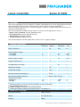
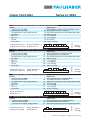
13. DIP Switch settings for various operating modes
Operating mode / DIP Switches
1
2
3
4
Motor-Tacho regulation (Speed control)
on
A
IR regulation (Speed control)
on
A
Voltage drive regulation (Voltage control)
on
Current control regulation (Torque control)
on
5
on
6
7
8
on
on
on
9
0
B
on
on
B
on
on
B
A
B
A. DIP Switch 4
This switch should be off if the command signal comes from a potentiometer connected
to the V-ref terminals. This switch should be on if an external voltage is used.
B. DIP Switch 0
This switch should be on when the dynamic current limit I-dyn is set using the on-board trimmer.
This switch should be off if the dynamic current limit I-dyn is externally set.
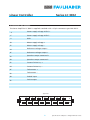
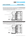
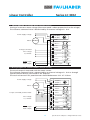
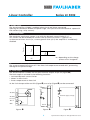
14. On-board trimmers and LEDs
The on-board trimmers have a twenty (20) turn range. Before operating the amplifier the
trimmers have to be set according to the following table.
Position
Function
RPM
CCW
Min. speed
Speed selection
IR
CCW
Min. stiffness
IR compensation
Max. continuous current
Continuous current
I-dyn
Offset
XP
I-max
CW
Middle
CCW
CW
LED1
Zero output balance
Min. stiffness
Amplification control
Max. intermittent current
Short duration current
Power
Power supply indicator
Green
>
I-max
On if I-max is exceeded
Red
LED3
>
T-max
On if excess temperature
Red
▼ ▼ ▼
▼
▲
▼ ▼
red
Note:
In different operating modes not all
trimmers will be used.
Unused trimmers should be set to the
positions given in the table.
red
green
RPM
IR
I-dyn
Offset
XP
I-max
Power
I-max
T-max
LED2
⊗ ⊗ ⊗
6
Specifications subject to change without notice




![Final Report - [Almost] Daily Photos](http://vs1.manualzilla.com/store/data/005658230_1-ad9be13b69bd4f2e15f58148160b0f22-150x150.png)