1
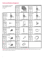
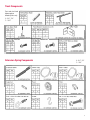
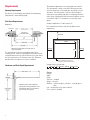
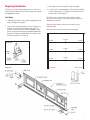
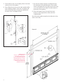
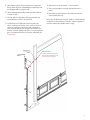
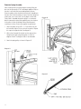
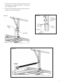
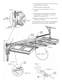
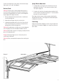
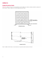
Garage Door
Installation Instructions
Garage Door Installation Instructions
These instructions are meant to provide a guideline as to how doors should be installed. It is important to recognize that each installation
will always present unique challenges that we may not address in this manual. New England Door recommends that only those
qualified individuals with experience in construction should attempt to install a door.
As always, all state and federal rules, laws, regulations and building codes, will be applicable first and foremost.
Prior to Installation
Before beginning you should review the entire manual in order to
familiarize yourself with all that is involved. You should then
layout all of the parts and components in an attempt to gain a
level of understanding of each item. Parts listed are for specific
sizes as listed in the instructions.
Safety First
As with all construction related projects, safety must come first.
Knowledge of the proper use of tools is essential. A garage door
is typically the single largest moving item on a house and as such
a tremendous amount of caution should be involved with the
assembling of this product. All warnings should be taken very
seriously. Protective equipment such as eyewear and gloves are
recommended.
Warning
A garage door when completely installed is designed as a
moving object. In order to create enough force for the
weight of the door to be lifted, a particular type of spring
system is utilized. Once fully assembled and “sprung” this
system is under tremendous tension. Spring systems
pose a significant amount of danger and risk. Improper
installation of this system or unfamiliarity with respect to
the correct way to install these components could result in
serious injury.
already in place, and a knowledge regarding the safety
precautions necessary to remove the tension without
risking injury.
The bottom brackets on garage doors are under significant
stress. Never attempt to remove these brackets without
having released all of the spring and cable tension first.
Refer to extension spring assembly on page 14. These
components are under tremendous stress and could fly
away from the door if loosened. Failure to follow this
precautionary step could result in serious injury or death.
Always use parts as supplied and never substitute
components as this change could result in premature aging
or failure of parts or pieces.
Always use the tracks as they are supplied with the door.
The rear of the horizontal tracks should be braced in such a
way as to provide adequate support and to remove the
possibility of swaying or spreading. These braces act as
stabilizers and will hold the track in place as the door is
traveling through the opening. Proper alignment and
reinforcement of the track is needed to prevent the door
from falling out of the horizontal position.
Never allow children to play on, under or with your garage
door or the electric opener if one is attached. These large
moving devices are extremely dangerous and are not
intended as toys.
Extension spring doors should never be installed without a
spring containment system, safety cables. Furthermore,
doors with extension springs in place currently, should
never be serviced without these same safety systems
2
© 2005 New England Door, LLC
6/05
Table of Contents
Installation Warnings . . . . . . . . . . . . . . . . . . . . . . . . . . . . . . . 2
Determining Proper Size and Ordering Information
for Your New England Door Brand Garage Door . . . . . . . . . . 3
Required Tool List . . . . . . . . . . . . . . . . . . . . . . . . . . . . . . . . . . 3
Section and Hardware Components. . . . . . . . . . . . . . . . . . . . 4
Track Components . . . . . . . . . . . . . . . . . . . . . . . . . . . . . . . . . . 5
Extension Spring Components . . . . . . . . . . . . . . . . . . . . . . . . 5
Requirements. . . . . . . . . . . . . . . . . . . . . . . . . . . . . . . . . . . . . . 6
Installation . . . . . . . . . . . . . . . . . . . . . . . . . . . . . . . . . . . . . . . . 7
DASMA 116 - Handle Orientation Guide . . . . . . . . . . . . . . . 18
Determining proper size
and ordering information for your
New England Door Brand Garage Door.
The pictures illustrated on page 6 present a generic opening.
Contained in this are a variety of terms of which you may or may
not be familiar. The following definitions are provided as an aide
to better understand the basic information needed in order to
properly place an accurate door order.
Terms and Definitions:
Opening Dimension: The door size is calculated by measuring
the finished opening. Measurement is taken width by height, with
out measuring the stops or weather-stripping.
Door Header: The top of the opening which consists of a head
jamb and casing.
Opening Width: The inside opening dimension from left jamb to
right jamb.
Opening Height: The inside opening dimension from floor to
header.
Side room: This measurement is taken to ensure proper space
for mounting of track. It must be calculated for both sides of the
jamb with the smallest dimension being the most critical. To take
this dimension you measure from either jamb out away from the
opening to the closest obstruction or 5" which ever comes first.
Headroom: Vertical clearance from the bottom of the header to
the ceiling or closest obstruction. This dimension is critical to
ensure enough clearance for the proper operation of the door as it
travels up into the opening.
Note: The door size should equal the finished opening. Wood or
Vinyl stops and weather-stripping are available and sold
separately. These products must be installed to seal the door in
the opening.
Prior to the actual installation instructions you will see a
breakdown of components, which will include sections, hardware,
track and springs. Within each list you will find pictures pertaining to each part as well as a quantity-listing dependant upon the
door and size involved. This list pertains specifically to the sizes
listed only.
It is recommended that prior to any installation you read and
become familiar with the instructions. Next, layout your parts to
understand the steps involved with each procedure.
Safety should be your primary concern. Always wear protective
eyewear.
Required Tool List
Vise Grips, C Clamps, or Locking Pliers
Hammer
2 – 20d Nails
Rope
Screwdriver
Tape Measure
Level
Socket Wrench Kit
Pliers
Drill and Drill Bits
Step Ladder
Saw Horses
Additional Products
(Additional product not sold with door)
• Angle Iron – very important as this will act as the support for
the bracing of the horizontal track.
• Vinyl or wood weather-stripping – will seal the jamb and door.
• Struts or operator brackets – these products provide additional
structural support in the event a garage door opener is
installed.
3
Section and Hardware Components
Parts and quantities listed below
apply to following sizes only:
A – 8'x7', 9'x7'
C – 16'x7'
Warning: Fasteners used to attach bottom fixtures should be colored red to signify Danger. Never remove these fasteners from a door
while the springs and cable are under tension.
4
Track Components
Parts and sizes listed
below apply to
following sizes only:
A – 8'x7', 9'x7'
C – 16'x7'
Extension Spring Components
A – 8'x7', 9'x7'
C – 16'x7'
5
Requirements
Opening Requirements
The door size is calculated by measuring the finished opening.
Measurement is taken width by height.
Side Room Requirements
Diagram A
The headroom requirement is to ensure proper track selection.
This measurement is taken as the vertical clearance measurement from the bottom of the header up to the ceiling or closest
obstruction. This measurement is critical to allow the door to
travel up out of the opening and back into the garage. Minimum
values shown. Whenever possible allow more headroom for ease
of installation. Add 2 1/2" to headroom if you are using a door
opener.
Headroom required for 12" radius track is 10".
Floor should be level. Bottom seal will only adapt to minor
imperfections.
DOOR FRAME
DOOR
JAMB
Headroom
Width
Whenever possible allow more side room for
ease of installation.
Sideroom
Height
This measurement is taken to ensure proper space for the
mounting of track. It must be calculated from both sides with the
smallest dimension the most critical. Measure out to each side to
the closest obstruction or 5" whichever comes first. Whenever
possible allow more side room for ease of installation.
Headroom and Back Depth Requirements
Floor
Floor should be level. Bottom seal
will adapt to only minor imperfections.
Example of door size and order:
1 – 9'w x 7'h, 12"R, Extension Springs, solid, no lock
Quantity Width
Minimum values shown. Whenever
possible allow more headroom for ease
of installation. Add 2 1/2" to headroom if
you are using a door opener.
6
Sideroom
Height
Track
Size
Springs
Windows
Lock
Choices:
Quantity
Width
Height
Track size – standard
Springs – extension
Windows – solid or with glass, with glass – insert designs or
plain
Lock – through door lock or interior side lock
Color – options if available
Beginning Installation
3. Attach bottom fixtures using RED fasteners provided.
As always, use caution when working with tools. Start with a
clean and unobstructed work area and wear protective eyewear
and appropriate clothing.
4. As each section is hardwared place roller into each end hinge
in roller carrier position. See Diagram A. Also place rollers in
bottom fixtures. See Diagram B.
Let’s Begin
Note: The bottom section usually has the rubber astragal
attached. In some instances it may be necessary to attach this
rubber piece in the field.
1. Temporarily nail wood or vinyl weather stripping flush with
wall. See Diagram A on page 6.
2. Sections are connected together by the use of hinges (see
diagram A.) Each hinge is numbered specifically for its
location on the door. Locate #1 hinges and apply to top of
bottom section utilizing fasteners provided and depicted in
Diagram B. All hinges are applied with the number on the
bottom leaf and the slots at the top.
Warning: Bottom fixture fasteners must be red in color to
indicate danger.
Note: The bottom section must be level in the opening.
#1 Hinge
#3 Hinge
#3 Hinge
Diagram A
#1 Hinge
#2 Hinge
#2 Hinge
#1 Hinge
#1 Hinge
Diagram B
Bottom Fixture
#1 Hinge
Bottom Fixture
7
5. Place the bottom section into the opening. Check for level and
center the section in the opening.
6. Drive a 20d nail into the fame on each side to provide stability
while completing installation. These nails are temporary and
will be removed later. Drive nail in part way and bend over
the end of section. See Diagram B. Below.
Diagram A
7. Now select left vertical track piece. See Diagram A Below.
Each vertical piece will need jamb brackets to be installed.
Vertical tracks progressively move further away from the jamb
as you move up from floor to header. This allows the door to
break away from the opening.
8. Refer to parts page for items to be used. Attach jamb
brackets to track using track bolts and nuts, but do not
completely tighten.
Note: Bolt heads should be inserted into the inside track to allow
rollers to move freely.
Diagram B
Reference Line:
This line is used on both sides of
the opening to determine the
location at which the vertical and
horizontal tracks meet. To ensure
proper working of the door, these
locations must be level in the
opening with each other.
8
9. Vertical pieces may be used on either the left or right side.
Always make certain the rounded edge is inward facing and
the 90-degree edge is facing the jamb.
13. Space bottom of the track about 1" from the section.
14. Attach the flag angle to the jamb; again making sure it is
plumb.
10. Attach flag angle again making certain track bolt heads are
on inside of track.
15. Next adjust the track brackets to the jamb and secure the
track assembly with lags.
11. The flag angle is a splice piece allowing the vertical and
horizontal portion of track to be connected.
12. Install vertical track: Slide vertical track into place over
rollers. Install lags into jamb in a loose fashion to allow for
corrections. Important, verticals will need to be plumb to
allow for proper spacing. Also the top of each vertical must
be level on the left and right side. This is a critically important
part of maintaining the balance of the door, indicated by the
reference line.
FLAG
ANGLE
Note: Once all adjustments have been made for a plumb and level
installation, be sure to tighten all fasteners. Failure to tighten all
fasteners could result in product failure or injury.
Reference Line:
Location where horizontal track
will meet the vertical track. This
must be level on both sides.
9
Section Installation
1. Take the next section to be installed and apply hinges at the
upper corners. This section will have #2 hinges on the ends.
As always throughout the door #1 hinges are installed in the
center. The appropriate number on the end hinge will increase
as you progress up the door. See diagram on page 7.
2. Insert rollers into the hinges in the roller carrier position.
3. Place this section onto the bottom section by twisting it into
place in the track and then lowering it onto the section.
4. Flip the hinge from the bottom section up and use hinge
fasteners provided to attach to the newly placed section.
Fasten hinge in each location.
10
5. Repeat this process for remaining sections except the top
section. Caution should be used, as the door is only secure on
one side.
6. Repeat steps 8 thru 15 in the previous section on the opposite
side to install remaining vertical. Once both are firmly in
place, remove nails in jamb.
Important: The top section of any door electrically operated must
include additional support to prevent damaging the door. A strut
must be installed or the warranty will be void.
Strut Installation
Any door supplied with only 1 strut should have it installed on the
top section.
1. Locate the strut at the top of the section and attach with selfdrilling screws on both top and bottom flanges of the strut at
both ends and all intermediate stiles.
The top fixture will be installed later, directly below the strut.
See Diagram A.
DIAGRAM A
11
Installing Horizontal Track
1. In order to attach the horizontal to the vertical track a
temporary support should be used, as is pictured below.
2. Once temporary support is in place, and track is secure, lift
track into place.
3. Fasten horizontal curve to the vertical using track bolts and
nuts supplied. Always fasten by inserting head of bolt through
track inside to outside. (See Diagram.)
4. Attach angle of horizontal track to flag angle using carriage
bolts provided. Again be sure to insert bolt through track to
ensure door does not hit the bolt when operating. See
diagram.
Warning: Rope is a temporary support only. Permanent support
must handle a 400lb load. See installation of track hanging
supports on page 13. Failure to install permanent and proper
support could result in severe injury. These supports are not
supplied with the door and must be purchased separately.
We recommend using an angle iron 11/2" x 11/2" x 3/32" with
5/16" x 1" bolts.
Top Fixtures
1. Now apply top fixtures and rollers to the top section.
2. Adjust fixture to ensure a tight seal of door against door seal.
Temporary Support
Permanent support
must be installed to
structural overhead
member prior to the
door being raised
into the opening.
12
Installation of Horizontal Track Hanging Supports
1. Before proceeding check to make certain all hardware,
fasteners, lags, or bolts installed up to this point, are securely
tightened. The vertical tack should now be permanently
affixed to the jamb.
2. Slowly lift the door, not more than halfway up and into the
opening to check for a smooth operation through the curved
track. Then slowly lower to fully closed position. DO NOT
OPEN DOOR FULLY AT THIS POINT.
3. Horizontal tracks must be square with the header. To check,
measure from left flag bracket back in opening along
horizontal 80" and mark. Next measure across header from
Diagram A
flag bracket 60" and mark. Then connect these marks
diagonally to reach 100" by moving the horizontal inward or
outward. Mark the ceiling for hanger location. Repeat step for
right side hanger. See Diagram A. Track hangers should be
1 1/2" x 11/2" x 3/32" angle iron using 5/16" x 1" bolts.
4. Assemble track hang support as illustrated in Diagram B.
Always attach each track hang to a structural ceiling member
with 3 – 5/16" x 1 3/4" wood lags. Lift the rear of the horizontal
to about 1" above level then attach track to permanent
support with 5/16" x 1" bolts, washers and nuts. Install a bolt
at the back of the horizontal to prevent the door from exiting
the back of the horizontal. See diagram B – door stop.
Warning: Failure to securely support and brace the upper track
assembly or failure to properly install track supports to ceiling can
cause the door to fall out of the opening causing serious injury or
death.
Warning: Top brace must be securely fastened to a structural
member to avoid serious injury.
Warning: Once the supports are permanently in place and
attached to the horizontal tracks, take measurements to check for
squareness. The space at the header between the horizontals
must be the same as at the back of the opening between the horizontals.
Attaching a Pull Rope
Danger, if an operator is to be used never have a pull rope
installed. The use of a rope on an electrically operated door can
cause serious injury. If a door is manually operated and later has
a garage door operator installed, remove the rope immediately.
1. Only attach a pull rope to a manually operated door. To do so
attach an eye screw about 50" from the floor to the jamb.
Next, tie one end of the rope to the roller stem on the bottom
fixture between the tabs, which hold it in place. Then tie the
other end to the eye screw.
Diagram B
Warning: A garage door has many parts. Always keep hands and
fingers away from the door. Never allow children to play with the
door. Never place fingers in or near section joints while door is
moving.
Complete installation of jamb weather-stripping at this point, if
applicable. The weather-stripping is sold separately but is
recommended to ensure a snug and weather tight fit. This was
temporarily installed in the first step on page 7.
13
Extension Spring Assembly
Note: Installing extension springs requires manually lifting the
door into the open position. This could require additional help, as
the door is very heavy. Before proceeding identify all parts.
Extension springs mount along the horizontal track, expanding as
the door closes and contracting as it opens. Extension springs are
used in pairs, one on each side. You may begin on either side.
Safety cable is threaded through the spring as a containment
device to prevent the spring from propelling away from the door
in the event of failure or breakage. Never substitute parts if
something is missing. Contact your supplier for replacement.
Diagram B
1. Attach the pulley using a 3/8" x 1 1/2" bolt and hex nut onto
the horizontal angle as close to the wall as practical. Repeat
this step for the opposite side. See diagram A.
2. With at least 2 people lift the door into the open position.
Clamp the door open using locking pliers as shown in
diagrams B and C. Locking both sides is recommended.
3. Attach the spring pulley as shown in Diagram D.
Diagram A
Diagram C - Reverse Side
Diagram D
14
4. Securely attach safety cable to back hang and then attach the
eye bolt below it. The eye bolt should be 6" – 10" above the
track. See diagrams E and F.
5. Thread safety cable through the spring assembly. Attach the
spring to the eye bolt. See diagram G.
Diagram E
Diagram F
Diagram G
15
6. Attach spring cable loop in Diagram H to bottom fixture stud
and thread spring cable over pulley.
7. Thread spring cable around spring pulley.
Diagram H
8. Tie off cable to a cable clip and attach an “S” hook,
Diagram K.
9. Stretch the spring 2" or 3" and clip the “S” hook into the
horizontal angle. This “initial tension” may need to be
adjusted later. See diagrams I and J.
10. Repeat this on the opposite side, be sure to make the cable
assemblies the same length.
Note: Upon completion of door installation, if the spring requires
further adjustment, it will be through the “initial tension.”
Diagram I
Diagram J
Diagram K
16
Connect remaining end of safety cable to the horizontal angle.
Never attach it to a wall. See diagram L.
Balance Check
Spring Balance Adjustment
1. If the door picks up off the floor the initial tension must be
reduced by moving the “S” hook away from the door jamb.
See step 9 on page 16.
Warning: The door now has been sprung and the tension is
active. Be certain all adjustments have been finalized. Before
removing the clamping devices, be certain you have adequate
help to support full weight of the door.
2. If the door rolls back into the opening when raised the initial
tension must be increased by moving the “S” hook toward the
door jamb. See step 9 on page 16.
1. Remove clamp and slowly lower the door, it should move
smoothly through track.
Note: Again in both instances the door springs should only be
adjusted when the door is in the up position and locked in place
to reduce the risk of injury.
2. Keep hands and fingers away from section joints.
3. A properly balanced door will not lift off the floor by itself
when in the down position, and will not roll back into the
opening when raised in the up position.
Warning: Any adjustments to the door now are very dangerous
since the springs are active and under tremendous tension.
Final Fitting
Reposition the weather-stripping to ensure a snug fit against the
door. Note: If this weather-stripping is too snug it may cause the
door to bind.
Warning: Never adjust any part of the spring assembly while the
door is in the down position.
Danger: Never place fingers near or in the section joint as
serious injury could result.
Warning: Always wear protective eyewear when servicing the
door.
Diagram L
17
DASMA 116
Handle Orientation Guide
Warning: To avoid the risk of injury it is recommended that four (4) lift handles (two inside/two outside) be installed in accordance with
these instructions. Failure to adhere to this orientation guide could result in injury.
Note: If a handle is within 4 inches of a section interface, it must promote vertical orientation of the hand.
18
New England Door, LLC 15 Campanelli Circle, Canton, MA 02021-2480
Tel. 800-969-5151 ■ 781-821-2737 ■ Fax 781-821-8050 ■ E-mail us at [email protected] ■ www.nedoor.com
Specifications of product are subject to change without notice.
7/05