1
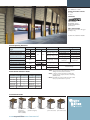
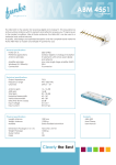
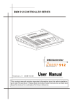
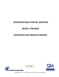
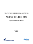
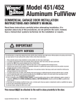
T H E R M O S PA N ®
WAY N E - DA LTO N C O M M E R C I A L D O O R S Y S T E M S
T H E R M O S PA N ® 1 5 0
150
SECTIONAL DOOR SYSTEMS
INSULATED SECTIONAL STEEL DOORS CUT YOUR TOTAL COST
Wayne-Dalton’s Thermospan 150 polyurethane insulated door
provides excellent thermal efficiency. Featuring an R-value of
14.16 and a U-value of .0706, the Thermospan 150 is an excellent
value when energy efficiency is important but strength, rigidity
and durability can’t be compromised.
The Wayne-Dalton Thermospan Series doors are the only doors
in the industry with patented, roll-formed integral struts on each
section, making them the most rigid doors available.
• EXCELLENT THERMAL
QUALITIES (R-VALUE = 14.16,
U-VALUE = 0.0706)
• STANDARD SIZES UP TO
26’ 2” WIDE AND 20’ 1” HIGH
• COMMERCIAL/INDUSTRIAL
DURABILITY
• INTEGRAL STEEL STRUTS
FOR SUPERIOR STRENGTH
SECTIONAL DOOR SYSTEMS
T H E R M O S PA N ® 1 5 0
Popular in a wide variety of commercial and
industrial applications, the Thermospan 150 offers
a strong combination of characteristics, including
strength, rigidity, longer life and energy efficiency at
a highly competitive price.
The Thermospan 150 is manufactured using our
patented, continuous foamed-in-place technology,
in which the polyurethane core is securely
bonded to hot-dipped galvanized inner and outer
skins. This process gives the Thermospan 150
outstanding thermal, strength, and bonding
characteristics while creating a door that is
significantly more efficient than conventional
insulated steel doors.A designed-in joint seal also
helps save energy by preventing air filtration.
Optional factory glazed windows and aluminum
full view panels, combined with two standard
finishes (white and brown), can help ensure that
the Thermospan 150 meets your aesthetic
requirements as well.
Materials & Construction
The Thermospan 150 is designed for easy
installation, rugged durability and longer life.
Features such as 18-gauge steel end caps and
two 1 3⁄4" roll-formed struts on each section give
the Thermospan 150 increased rigidity, while the
factory finished interior and exterior hot-dipped,
galvanized skins make installation easier, add life
to the door and provide greater durability.
The Thermospan 150 also features hardware
plates at all fastener points to add durability and
extend the life of the door.
Flush door embossed pinstriping
(grooves) on outer skin adds strength and
non-repeating random stucco exterior
enhances appearance.
Thermal break separates inner & outer
skins at top and bottom so virtually no heat
or cold is conducted through the section.
Prepainted inner and outer skins for
added corrosion-resistance.
NOTE: Both skins are also hot-dipped
galvanized steel for further protection
against corrosion.
Integral struts
Two 1 3/4" roll-formed struts
per section add rigidity and
strength.
18-gauge “wrap-around”
end caps offer interior
hinge attachment surface
and exterior leg for proper
seal against jamb.
Solid polyurethane
core adds to insulating
efficiency.
Joint seal prevents air
infiltration and saves energy.
Extended Limited Warranty
TEN (10) YEARS against cracking, splitting or deterioration due to rust.
SEVEN (7) YEARS against separation of polyurethane from the steel skin of the panel.
Contact Wayne-Dalton for additional sizes and
colors.
Performance Options
Window Options
•
•
•
•
High Cycle Spring (25K, 50K, 100K)
3"Track Option
Solid Shafts
PerimeterWeatherseal
Special Application Options
• SpecialTrack Designs
• Mullions
• Windload
Vision Lites allow for visibility while
maintaining security
Aluminum full view sections allow for maximum
natural light and visibility
Operation Options
Safety Options
• Chain Hoist Operation
• Motor Operation
• Broken Cable Devices
• Safety Edges
• Safety Photo Eyes
www.wayne-dalton.com/commercial
Color Options
Brown Embossed
Stucco Finish
White Embossed
Stucco Finish
STANDARD SIZES UP TO:
26’ 2” WIDE & 20’ 1” HIGH
ENERGY EFFICIENCY VALUES:
U = 0.0706
R = 14.16
WINDLOAD:
MEET OR EXCEED
ANSI/DASMA 102-2003
IN ACCORDANCE WITH
ASTM E-330-70.
BEST APPLICATIONS:
Where thermal performance and rugged
durability are key
U.S. Patent Nos. 4238544 and 4339487
General Operating Clearances
Headroom***
Sideroom**
Depth Into Room
Type
2" track 3" track 2" track 3" track
2" & 3" track
Standard Lift Manual12"R
121⁄2-17"
NA
Opening Height +18"
Standard Lift Manual15"R
141⁄2-20" 151⁄2-21"
Standard Lift Motor Oper. 12"R 15-191⁄2"
NA
41⁄2"
51⁄2"
Opening Height +66"
1
1
Standard Lift Motor Oper. 15"R 15-19 ⁄2" 18-23 ⁄2"
High Lift Manual
Door Height
Opening Height – Lift +30"
+12"
High Lift Motor Oper.
24" One Side
Door Height
Vertical Lift Manual 12"R
41⁄2"
51⁄2"
Opening Height +18"
+20"
Vertical Lift Motor Oper. 12"R
24" One Side
Low Headroom Manual*
6-141⁄2"
6-141⁄2"
Opening Height +20" - 26"
6"
9"
1
Low Headroom Motor Oper.* 8 ⁄2-17"
81⁄2-17"
Opening Height +66"
Panel/Section Selection Guide
Door Section and Lite Selection
Door Width No. Panels Max. No.Windows
Up to 9'2"
2
2
9'3" to 12'2"
3
3
12'3" to 16'2"
4
4
16'3" to 19'2"
5
5
19'3" to 24'2"
6
7
24'3" & up
Call Factory
Door Height and Section Selection
Door Height
No. Sections
Up thru 8'1"
4
8'2" thru 10'1"
5
10'2" thru 12'1"
6
12'2" thru 14'1"
7
14'2" thru 16'1"
8
16'2" & up
Call Factory
Center Line of Springs
2" track
3" track
Opening Height +12"
NA
Opening Height +13" Opening Height +14"
Opening Height +12"
NA
Opening Height +13" Opening Height +14"
Opening Height
Opening Height
+Lift +61⁄2"
+Lift +71⁄2"
Double Door Height
+13"
Does Not Apply
*Note: Rear mount torsion requirements shown on chart. See
drawings for front mount torsion clearances.
**Note: 8” sideroom required, one sidefor doors having chain
hoist. 24" side room required, one side for doors having
jackshaft operators.
***Note: Clear headroom is based on cable size so please contact
factory for specific headroom for your door.
Track Selection Guide
Standard Lift
High Lift
(break-away is
standard, straight
incline is available)
Roof Pitch
(standard or high lift)
Vertical Lift
www.wayne-dalton.com/commercial
Low Headroom
(rear mount torsion)
Low Headroom
(front mount torsion)
SECTIONAL DOOR SYSTEMS
T H E R M O S PA N ® 15 0
Note to specifiers: Words in parentheses indicate frequently specified and highly recommended options.
PART I – GENERAL
1.01 Section Includes
A. Sectional overhead doors [manually] [motor]
operated with accessories and components.
1.02 Related Work
A. Opening preparation,miscellaneous or structural
steel work, access panels, finish or field painting
are in the scope of work of other trades and
divisions of these specifications.
1.03 Reference Standards
A. ANSI/DASMA 102-2003– American
National Standards Institute Specifications for
sectional overhead doors published by Door &
Access Systems Manufacturers Association
International.
B. ASTM A229 – Steel wire, oil- tempered for
mechanical springs.
C. ASTM A-653-9A – Steel sheet, zinc-coated
[galvanized] by the hot-dipped process,
commercial quality.
D. ASTM D1929 – Ignition temperature test to
determine flash and ignition temperature of
foamed plastics.
E. ASTM E84-91A – Tunnel test for flame spread
and smoke developed index.
F. ASTM E330 – Structural performance of
exterior windows, curtain walls, and doors by
uniform static air pressure difference.
G. ASTM E413-87 – Sound transmission class
acoustical performance value = 21.
H. ASTM E1332-90 – Outdoor-indoor
transmission class acoustical performance
value = 19.
I. ASTM E283-91 – Air infiltration = 0.23
CFM/FT 2 at 15MPH
1.04 Quality Assurance
A. Sectional overhead doors and all accessories
and components required for complete and
secure installations shall be manufactured as a
system from one manufacturer.
B. Sectional overhead doors shall be tested and
labeled certifying compliance with ASTM
D1929 and ASTM E84-91A standards.
1.05 Systems Description
A. Sectional Overhead Door: Type:
Thermospan 150 [flush]
B. Mounting: Continuous angle mounting for
[steel] [wood] jambs [bracket mount to wood]
C. Operation: [manual push-up] [chain hoist]
[motor] [motor with chain hoist]
D. Material: Galvanized steel with polyester finish paint
E. Insulation: Polyurethane
1.06 Submittals
A. Shop Drawings: Clearly indicate the following:
1. Design and installation details to withstand
standard windload.
2. All details required for complete operation
and installation.
3. Hardware locations.
4. Type of metal and finish for door sections.
5. Finish for miscellaneous components
and accessories.
B. Product Data: Indicating manufacturer’s product
data, and installation instructions.
1.07 Delivery, Handling, Storage
A. Deliver products in manufacturer’s original
containers,dry,undamaged,seals and labels intact.
B. Store and protect products in accordance with
manufacturer’s recommendations.
1.08 Warranty
A. Provide manufacturer’s standard SEVENYEAR
warranty against separation/degradation of the
polyurethane foam from the steel skin of the
panel under provisions of Section 01700.
Standard manufacturer’s TENYEAR warranty
against cracking, splitting or deterioration due to
rust-through.
PART II – PRODUCTS
2.01 Manufacturer
A. Wayne-Dalton or approved equal
Thermospan 150 insulated sectional
overhead doors of steel construction complete
as specified in this section and as manufactured
byWayne-Dalton Corp., Mt. Hope, Ohio.
2.02 Materials
A. Door Sections: Shall be of steel/polyurethane/
steel sandwich type construction with thermal
break and calculated materials “R”-value of
14.16, in accordance with industry guidelines.
1. Exterior Skin: Structural quality, hot-dipped
galvanized steel, .022" minimum embossing,
factory finished with baked-on polyester
primer and [white] [brown] polyester finish
coats with [non-repeating random stucco
texture and 1⁄4" wide pinstriping].
2. Interior Skin: Structural quality, hot-dipped,
galvanized steel, factory-finished with a
polyester primer and white finish coat.
Interior skin shall have two 13⁄4" roll-formed
integral struts per section.
3. Ends of section shall be sealed with [16-gauge]
[18-Gauge]hot-dipped galvanized steel full-height
end caps.
4. Insulation: Cavity shall be filled with formed
in-place CFC free polyurethane core
separated by a factory extruded thermal break.
5. Insulated sections shall be tested by an I.C.B.O.
certified laboratory in accordance with
ASTM E-84-91A and shall achieve a
Flamespread Index of 10 or less,and a Smoke
Developed Index of 210 or less.
6. Insulation material shall be tested by an
I.C.B.O. certified laboratory in accordance
with ASTM D-1929 and shall achieve a
minimum Flash Ignition temperature of 734
degrees F, and a minimum Self Ignition
temperature of 950 degrees F.
7. Insulated sections shall be tested and meet all
requirements of the UBC 17-5 corner burn.
B. Track: Track design shall be [standard lift]
[high lift] [vertical lift] [low headroom].Vertical
mounting angles and brackets shall be hot-dipped
galvanized.Track size shall be [2"] [3"].Vertical track
shall be graduated to provide wedge type weathertight closing with continuous angle mounting for
[steel] [wood] jambs, and shall be fully adjustable to
seal door at jambs. Horizontal track shall be
reinforced with continuous angle of adequate
length and gauge to help prevent deflection.
Note: Horizontal track applies to standard lift,
high lift, low headroom and
follow-the-roof designs only.
C. Hardware: Hinge and Roller Assembly:
1. Hinges and brackets shall be made from
hot-dipped, galvanized steel.
2.
Track rollers shall be case-hardened inner steel races
with 10-ball [2"] [3"] rollers.
3. All factory authorized attachments shall be
made at locations indicated and reinforced with
backup plates.
D. Counterbalance:
1. Springs shall be torsion type, low-stress,
helical wound, oil-tempered spring wire to
provide minimum [10,000] [25,000][50,000]
[100,000] cycles of use, on continuous steel
[solid CRS] shaft.
2. Spring fittings and drums made of die cast,
high-strength aluminum.
3. Pre-formed galvanized steel aircraft cable shall
provide a minimum of a 5:1 safety factor.
2.03 Operation
A. Operation shall be [manual push-up] [chain hoist]
[motor] [motor with chain hoist].
Note: Manufacturer does not recommend
chain hoists or jack shaft operators on
the following track applications.
• 15" radius standard lift with roof
pitch less than 2:12
• Hi-lift less than 24"
• Hi-lift between 12" – 23" with roof
pitch less than 1:12
• Low headroom track
Special chain hoist assemblies (using a trolley
rail) are available for the above track systems.
2.04
Locks
A. Locks shall engage the right-hand vertical track
and utilize [an interior side lock]
[standard size rim cylinder].
2.05
Weatherstripping
A. Doors shall be equipped with factory-applied
co-polymer joint seals between sections
and vinyl “bulb” shaped astragal provided for
bottom section. Optional top head seal and
jamb seals are also available.
2.06
Glazing
A. Optional.
2.07 Windload
A. Windload – per DASMA 102-2003 and as required by
local codes.
PART III – EXECUTION
3.01 Installation
A. General:
1. Install doors in accordance with manufacturer’s
instructions and standards. Installation shall be
by an authorizedWayne-Dalton representative.
2. Verify that existing conditions are ready to
receive sectional overhead door work.
3. Beginning of sectional overhead door work
means acceptance of existing conditions.
B. Install door complete with necessary hardware,
jamb and head mold strips, anchors, inserts,
hangers, and equipment supports in accordance
with final shop drawings, manufacturer’s
instructions, and as specified herein.
C. Fit, align and adjust sectional overhead door
assemblies level and plumb for smooth operation.
D. Upon completion of final installation lubricate, test
and adjust doors to operate easily, free from warp,
twist or distortion and fitting for entire perimeter.
Note: Architect may consider providing a
schedule when more than one sectional
over-head door or opening type is required.
Specifications and technical information also available at www.arcat.com, SpecWizard™, and Sweets.com®.
Distributed By:
www.wayne-dalton.com/commercial
For technical information, visit:
© 2007 Wayne-Dalton Corp. • One Door Drive • Mt. Hope, Ohio 44660 • 800-764-1457
Mt. Hope, OH • Dalton, OH • Trail, OH • Pensacola, FL • Portland, OR
Printed in U.S.A.
Item #332535 Revised 9/2007