1
Domestic Air Conditioner
SERVICE MANUAL
Models :
H2SM-14HC03/R2
H2SM-18HC03/R2
Features
Comfortable:wide-angle airflow
Health air purifying
Quiet operation
Engergy efficient
Wide variety of functions
Serial Number:
Versio n:00.00
Edition: 2005-3-25
Domestic Air Conditioner
1.
2.
3.
4.
Content
Model: H2SM-14HC03/R2
H2SM-18HC03/R2
Description of product model coding and series introduction
Specifications
Curves of performance
Description,net dimensions and functions of main component s
and accessories
5. Brief introduction to electrical control functions
6. Abnormity diagnose
7. Wiring diagram
8. Circuit diagram
9. Trouble shooting
10. Refrigerating cycle diagram
11. Noise level test chart and air velocity distribution
12. Installationmanual
1
Domestic Air Conditioner
Model: H2SM-14HC03/R2
H2SM-18HC03/R2
Description of product model
coding and series introduction
2
Model: H2SM-14HC03/R2
H2SM-18HC03/R2
Domestic Air Conditioner
A. Description of coding rules of unit model
1
2
3
4
5
6
7
8
9
10
The type of power supply
Developing sequence
Function code
C-cooling only
H-heat pump
e-electric aided heating
numbers based on thousand unit
The structure code of indoor & outdoor unit
The quantity of the indoor unit is two
H-Abbreviation of Haier
Examples:
H2SM-18HB03/R2,It represents wall-mounted multi-type split type room air conditioner.The cooling capacity
is 18000BTU/h,and the power supply is 220-230V/50Hz,”B” means the improvement
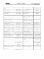
B.Standard Situation/Conditions
No.
Operating condition
indoor air status
DB C
WBOC
outdoor air status
DB C
WBOC
1
Norminal cooling
27OC
19OC
35OC
24OC
2
Norminal heating
20OC
15OC
7OC
6OC
3
Norminal electrical
heating
---
---
---
---
O
3
O
Domestic Air Conditioner
Model: H2SM-14HC03/R2
H2SM-18HC03/R2
C.Series brief introduction
1.comfortable:wide-angle airflow
The vertical dual-flap and horizontal wide-angle louvers ensure the cool(warm air reaches every
corner of the room.
2.Health air purifying and negative ion function
An air purifying filter with deodorizing and disinfecting functions
keeps the air clean and users
healthy.The negative ion generator can produce the negative ion that make the air fresher and cleaner.
3.Quiet operation
Fan With Random-pitched Blades.
Random-pitched blades help reduce operating noise while maintaining a high airflow rate.
2.Engergy efficient
The design of inner-grooved copper tube greatly increases the refrigerant contact area and the
efficiency of cooling/heating functions.
5.Convenience
Auto restart and washable panel:
The grille can be removed easily and washed when necessary.Any series have the function then
even if the power falls when the unit is operating unit will automatically return to the operating
settings in use before the power failure when power is restored.
6.Wide variety of functions
24-Hour Timer:
24-hour timer allows users to select the exact time they would like the air conditioner to turn on
and to turn off.Timers on previous models operation based on the number of hours of desired
operation.
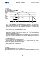
7.Night-set models
When the air conditioner is operationg on the timer-off circuit.The preset room temperature
gradually rises(going down in heating)before the unit stops as shown delow.Users can sleep
comfortably without sudden change in temperature.
8.Program”dry”
This function automatically reduces the level of humidity while maintaining the preset indoor
temperature.
4
Domestic Air Conditioner
Specifications
5
Model: H2SM-14HC03/R2
H2SM-18HC03/R2
Domestic Air Conditioner
Model: H2SM-14HC03/R2
H2SM-18HC03/R2
CURVES OF PERFORMANCE
OF COMPRESSOR
8
Model: H2SM-14HC03/R2
H2SM-18HC03/R2
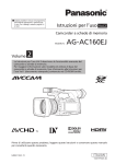
Domestic Air Conditioner
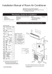
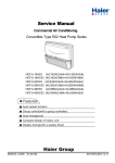
Performance Curve
Power Supply
220-230V / 50Hz / 1PH
Run Capacitor
25 μF / 370 VAC
Capacity (Kcal/Hr)
39A173A
Power (Watts)
Model
2500
2330
2160
1990
1820
1650
1480
1310
1140
970
800
900
865
830
795
760
725
690
655
620
585
550
35 C
Ambient Temperature
Cond. Temperature
45 OC
O
50 OC
55 C
O
60 C
-7
-6
-5
-4
-3
-2
-1
0
1
2
3
4
5
6
7
8
9
10
11
12
O
45 C
O
50 C
O
55 C
O
60 C
-8
Current (Amps)
8.3 C
Subcooling
-8
-7
-6
-5
-4
-3
-2
-1
0
1
2
3
4
5
6
7
8
9
10
11
12
O
4.00
3.85
3.70
3.55
3.40
3.25
3.10
2.95
2.80
2.65
2.50
60 C
O
55 C
O
50 C
O
45 C
-8
Flow (Kg/Hr)
35 C
Return Gas Temperature
-7
-6
-5
-4
-3
-2
-1
0
1
2
3
4
5
6
7
8
9
10
11
12
45 OC
O
50OC
55 C
O
60 C
55.0
51.5
48.0
44.5
41.0
37.5
34.0
30.5
27.0
23.5
20.0
-8
-7
-6
-5
-4
-3
-2
-1
0
1
2
3
4
5
6
Evaporating Temperature( C )
9
7
8
9
10
11
12
Model: H2SM-14HC03/R2
H2SM-18HC03/R2
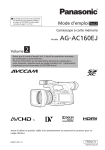
Domestic Air Conditioner
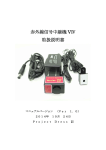
Performance Curve
35 C
Return Gas Temperature
Model
44A233A
Power Supply
220-230V / 50Hz / 1PH
Run Capacitor
40 uF / 370 VAC
8.3 C
Subcooling
35 C
Ambient Temperature
Cond. Temperature
Capacity (Kcal/Hr)
3500
3300
3100
2900
2700
2500
2300
2100
1900
1700
1500
45 C
50 C
55 C
60 C
Power (Watts)
-1
0
1
2
3
4
5
6
7
8
9
10
11
12
1150
1110
1070
1030
990
950
910
870
830
790
750
60 C
55 C
50 C
45 C
Current (Amps)
-1
1
2
3
4
5
6
7
8
9
10
11
12
5.3
5.1
4.9
4.7
4.5
4.3
4.1
3.9
3.7
3.5
3.3
60 C
55 C
50 C
45 C
-1
Flow (Kg/Hr)
0
0
1
2
3
4
5
6
7
8
9
10
11
12
45 C
50 C
55 C
60 C
70.0
66.8
63.6
60.4
57.2
54.0
50.8
47.6
44.4
41.2
38.0
-1
0
1
2
3
4
5
6
7
Evaporating Temperature( C )
10
8
9
10
11
12
Domestic Air Conditioner
Model: H2SM-14HC03/R2
H2SM-18HC03/R2
DESCRIPTION, DIMENSION
& FUNCTION OF MAIN
COMPONENTS AND ACCESSORIES
11
Domestic Air Conditioner
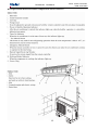
Description and function of main components and accessories
12
Model: H2SM-14HC03/R2
H2SM-18HC03/R2
Model: H2SM-14HC03/R2
H2SM-18HC03/R2
Domestic Air Conditioner
Net dimensions for indoor unit
182
265
795
Net dimensions for outdoor unit
680
295
583
815
869
319.5
352
13
Domestic Air Conditioner
Model: H2SM-14HC03/R2
H2SM-18HC03/R2
BRIEF INTRODUCTION TO
ELECTRICAL CONTROL FUNCTION
14
23
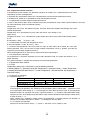
one. Temperature Control Function
In temperature control function, the operation frequency of outdoor unit is determined based on room
temperature and the set temperature.
In automatic fan speed mode, indoor fan is controlled based on the need of temperature control
In heating mode, indoor fan is controlled based on the temperature of coil.
1-1-1.Specification of Indoor Ambient Temperature Sensor
In case of short circuit or open circuit, indicator lamp alarms and indoor fan stops. When normal condition is resumed,
fan will automatically restart and operate normally.
Short Circuit:
o
Temperature: over 126 C, Hexadecimal System: over F8H, Resistance: below 0.65K,Voltage: over 4.85V.
Normal Temperature:
o
Temperature: 25 C, Hexadecimal System: 40H, Resistance: 23K, Voltage: 2.33V.
Open Circuit:
o
Temperature: below -31 C, Hexadecimal System: below 08H, Resistance: below 620K Voltage: below
0.15V.
o
B Parameter = 4200
R (25 C) = 23K
1-1-2 Specification of Indoor Coil Temperature Sensor
o
B Constant Number = 3700 R (25 C) = 10K¡
1-1-3 When heating operation starts and indoor fan stops or when within 30s of indoor fan starts after
heating operation starts, the resistant of indoor ambient temperature sensor is ignored. (to avoid the
impact of heat exchanger temperature over it.)
When forced operation ends after start-up, temperature zone control begins.
1-3. Set Temperature Correction
Set temperature is corrected according to unit model, operation mode, fan speed and whether it is in
power operation.
Fan speed correction is available only during low and mid heating operation.
1-4. Temperature Zone Control
1-4-1.Error
Temperature zone error is calculated as per the following formula:
In Heating Mode: E = (Remote Control Set Temperature + Correction Value) – Indoor Temperature
In Cooling & Dehumidification Mode: E = Indoor Temperature - (Remote Control Set Temperature +
Correction Value)
1-4-2 Compressor Shutdown
E is negative and |E|>T
T
Heating
TCHAHL
0.67
Cooling
TCHACL
0.33
After change of T
TCHAHH
0.67
TCHACH
1
T Change Condition
When operation starts E ı 3.0ć,
Compressor shuts down after continuous testing for 120s,
At the beginning of operation, with reference to the conditions given in above table, it operates based
on the parameters after change of T until compressor shuts down for the first time. In the time period
between compressor shutdown and restart, it operates based on T. (except in dehumidification mode)
Compressor starts at the beginning of operation or upon switch of operation mode (except standby ends)
or when E (error) > -T.
When compressor is operating, remote control set temperature is changing towards the direction of
compressor shutdown and when it is below –T, compressor will shut down.
2-4-3. Compressor Operation
Compressor restarts when E (error) > -ƸT+0.67ć and when 3 mins standby is over.
24
15
Domestic Air Conditioner
Model: H2SM-14HC03/R2
H2SM-18HC03/R2
two. Indoor Fan Control
2-1. Heating
2-1-1. Warm Start
Two. Cold Air Control in Heating Mode
Heat Exchange Temperature:
THHOT3
37.0ď
THHOT2
35.2ď
THHOT1
25.2ď
4mins
THHOTR
16ď
Stop
SLO
LO
Set
LO
SLO Stop
Conduct indoor fan control as per the above diagram and the heat exchange temperature.
1. Judge wind speed when heat exchange temperature is rising:
Fan is at super low level when heat exchange temperature is below 35.2ć.˄Fan will stop upon
initially energized into heating mode or after defrosting, or when heat exchange temperature is lower
than 25.2ć. Fan is at super low level when temperature is higher than 25.2ć but lower than 35.2
ć.˅;
Fan is at low level when heat exchange temperature is between 35.2ć and 37ć;
Fan will operate as per setting when heat exchange temperature is above 37ć.
2. Judge wind speed when heat exchange temperature is falling:
Fan is at low level when heat exchange temperature is below 35.2ć but above 25.2ć;
Fan is at super low level and will maintain the mode when heat exchange temperature is lower than
25.2ć˄Fan is at super low level upon initially energized into heating mode or after defrosting, or
heat exchange temperature is lower than 25.2ć but higher than 16ć; Fan will stop when heat
exchange temperature falls below 16ć.˅
3. Wind speed is at super low or low level when heat exchange temperature is rising. If heat exchange
temperature fails to enter the next temperature zone after 4 mins while wind speed rises to the next
stage, it is necessary to maintain the set wind speed for 4 mins before it is adjusted based on heat
exchange temperature.
4. When heat exchange temperature is falling, wind speed will return to set speed if low wind level is
maintained for over 4 mins.
2-1-2. 3 mins standby period when compressor shutdown.
1. When compressor shuts down˄temperature sensor is off˅, airflow is low for the initial 20s then
reduced to super low (When in silent operation, it is SSLO);
2. Wind is maintained at super low level in the standby period in heating mode˄Compressor stops during
mode switch.˅.
3. Remote control shut down and stop indoor fan.
2-1-3. Compressor Restart
When warm start, airflow is at remote control set level.
When in automatic airflow mode, airflow is determined based on temperature.
Refers to temperature zone control functions.
2-2 Cooling
Airflow is different when airflow is set at high, mid and low level.
When in automatic airflow mode, airflow is determined as per temperature. Refers to temperature control
functions.
2-3. Dehumidification
2-3-1. Compressor is off and is in 3 mins standby.
25
16
Domestic Air Conditioner
Model: H2SM-14HC03/R2
H2SM-18HC03/R2
Fan will stop if compressor stops
Fan is at super low level upon the end of 3 mins standby.
Compressor is on after 3 mins standby.
2-3-2. Compressor is on.
When airflow is set at high, mid or low level, fan will operate as per the setting.
When in automatic airflow mode, airflow is determined as per temperature.
three. Timed Operation
Time counting will start based on the difference of timer clock and current clock.
In timed operation, display panel timer lamp is on.
3-0-1. Timer Off
When timer off is set, panel timer lamp is on and unit will stop operation as per the timing.
3-0-2. Timer On
If timer on is set, when unit is off, panel timer lamp will be on and unit will resume operation as per the
timing and in set mode.
Execution sequence is based on the setting.
Four . Sleep Operation
When remote control set sleep mode, timer lamp is on.
o
4ˉ1. In cooling/dehumidification mode, set temperature will rise 1 C after 1 hour operation and another
o
1 C after the second hour. The unit will stop after another 6 hours.
o
o
4ˉ2. In heating mode, set temperature will fall 2 C after 1 hour and another 2 C after the second hour
o
and will rise 1 C after another 3 hours and the unit will stop after another 3 hours.
4ˉ3 If airflow of indoor fan is high before setting sleep mode, then it will turn into mid level after sleep
mode is set. If airflow of indoor fan is mid before setting, it will turn into low level after setting. If airflow of
indoor fan is low before setting, then it will not change after setting.
Five . Automatic Operation
4-1. Automatic Operation Mode:
On entering this mode, main control unit will decide the corresponding operation mode as per room
temperature to maintain the set temperature˄Set temperature is 23ćin heating mode and 26ć in
cooling mode.˅.
Upon initial startup, the unit will enter heating mode if room inlet air temperature is equal to or lower
than 23ć or it will enter cooling mode if temperature is higher than 23ć.
When entering heating mode, the unit will operate as per heating program˄set temperature is 23ć˅
Upon reaching temperature where compressor stops operation, compressor will stop and standby for 3
mins. In case it detects that inlet air temperature is higher than 27ć 15 mins after compressor stops, the
unit will enter cooling mode. Otherwise, the unit will remain in heating mode.
When entering cooling mode, the unit will operate as per cooling program˄set temperature is 26ć˅.
Temperature difference compensation is automatically cancelled. Upon reaching temperature where
compressor stops operation, compressor will stop and standby for 3 mins. In case it detects that inlet air
temperature is equal to or lower than 23ć 15 mins after compressor stops, the unit will enter heating
mode. Otherwise, the unit will remain in cooling mode.
If the unit changes into automatic mode from any other mode and if the operation mode is changed
(detect before operation), the unit will stop for 3 mins and it will operate based on inlet air temperature
after 3 mins.
Six . Trial Operation
Trial operation will end after 30 mins, after which unit shuts down. In trial operation, the unit will quit trial
operation mode upon reception of signal.
Compressor Stop Protection:
26
17
Domestic Air Conditioner
Model: H2SM-14HC03/R2
H2SM-18HC03/R2
Eight . EEPROM Control
When outdoor unit is supplied with power, if there is any inconsistency between EEPROM parameter and
checksum, EEPROM error.
When indoor unit receives EEPROM error signal from outdoor unit, it will display outdoor unit EEPROM error.
At this time, control and emergency operation are not acceptable.
It can only be cancelled through power off.
Nine . Error Detect Method
9-1. Indoor Temperature Sensor Error
In operation, an error occurs if the temperature is above 126 oC or below – 31oC.
Operation will resume automatically when temperature is outside the above range.
9-2. Heat Exchange Temperature Sensor Error
In operation, an error occurs if the temperature is above 196 oC or below – 53oC.
Operation will resume automatically when temperature is outside the above range.
In error condition, low load protection is cancelled.
9-4. Transmission Error
Based on the condition of communication between indoor and outdoor unit, in case outdoor unit fails to
receive signal within 20s after indoor unit sends out signal, transmission is abnormal. (except in the period of
first 2 mins when power is supplied.). It is confirmed as transmission error when outdoor unit receive the error
signal.
Transmission error is removed by stopping operation.
Ten . Special Function
10-1. Power-Off Compensation
a Entry Condition: Press sleep key 10 times in 7s and buzzer gives out 4 sounds and save the current status
into indoor unit EEPROM upon the entry.
b. On entering power-off compensation operation, indoor unit operates as per the following procedures:
Remote control emergency signal, and operates as per condition set by remote control and emergency setting
and save the current status into indoor unit EEPROM.
Main unit will operate as per condition set on panel board. And save the current status into indoor unit
EEPROM.
c. Exit Condition: Press sleep key 10 times in 7s and buzzer gives out 2 sounds
d. If timer and sleep features are set under power-off compensation condition, main unit memory is in a state
of shut-off if power is off and on again.
27
18
Domestic Air Conditioner
Model: H2SM-14HC03/R2
H2SM-18HC03/R2
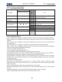
Eleven . Error Presentation Mode
11.1 Three Indicator Error Code
Operation
Operation Heating Cooling
Reset
Outdoor
Timer
Indoor
PS
Error Conditions
Automatic
Error Display
Cause
Indoor Senistor Error
ƾ
Ƶ
Ƶ
*
*
Indoor Heat Exchange
Senistor Error
ƾ
ƶ
ƶ
*
*
1. Connector loose contact or coil sensor
error.
Outdoor Senistor Error
ƶ
ƾ
Ƶ
*
Transmission Error
Ƶ
Ƶ
ƾ
1. Connector loose contact or sensor error
1. There is large interference source around
or wiring error.
EEPROM Error
ƾ
ƶ
ƾ
*
Indoor Fan Error
Ƶ
ƶ
ƾ
*
1. Connector loose contact or ambient
temperature sensor error.
Note
ƶOnƾBlinkƵOff
*
*
*
2. Wiring error or control panel error.
1. Whether control panel is damaged.
*
1. Whether control panel is damaged.
* This
function is
available.
Twelve . Emergency Switch
When shutdown, press emergency switch down for less than 5s, the unit will start emergency operation.
When shutdown, press emergency switch down for more than 5s but less than 10s, the unit will start trial
operation.
When shutdown, press emergency switch down for more than 10s but less than 15s, it will demonstrate
the previous error.
When shutdown, press emergency switch down, the panel will display automatic operation.
When shutdown, press emergency switch down for less than 15s, or remove hand from emergency
switch, the unit will not accept remote control signal.
Unit enters shutdown condition after 15s.
Unit can receive remote control signal after 15s.
Press emergency switch during operation, air-conditioner will shut down.,
During operation, if error occurs, press emergency switch to shut down the unit to clear error condition.
During error presentation, press emergency switch and error presentation will end.
During operation, if emergency switch is pressed continuously (press and hold) in normal or abnormal
condition (such as tact switch short circuit) or in error presentation condition, the unit can also receive
remote control signal.
Error Record Presentation Mode:
When press and hold switch for 10s it gives out 3 sounds, release switch to enter error record
presentation mode. Press and hold switch for 15s, panel display is off and error record presentation
mode is cancelled.
Previous alarm information will be sent to display panel for status display.
Error record presentation mode is cleared after 10s. (Error record presentation mode is only displayed
for 10s.)
During the presentation, no remote control signal except shutdown signal is accepted.
There is no presentation when no error occurs, only buzzer utters sound.
28
19
Domestic Air Conditioner
Model: H2SM-14HC03/R2
H2SM-18HC03/R2
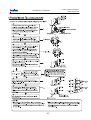
Outdoor PCB Function Manual
1. Single-unit cooling operation
1.1When the single unit’s indoor unit gives a cooling signal, the corresponding outdoor
compressor carries out cooling operation. During the operation, the outdoor fan operates 1
second before the compressor operates.
1.2When changed from heating to cooling, the compressor stands by for 3 minutes, the
outdoor fan operates to blow off remaining heat and stops 30 seconds later.
1.3When the outdoor ambient temperature T1ı38ć, the outdoor fan runs at the high
speed. There is a return difference of 2ć for the change between high and medium
speed.
When the outdoor ambient temperature T1İ26ć, the outdoor fan runs at the low
speed. There is a return difference of 2ć for the change between low and medium
speed.
When the outdoor ambient temperature T1İ8ć, the outdoor fan is in a cycle of 1
minute stop and 3 minute run. There is a return difference of 2ć for the change
between low speed and run and stop.
1.4Once the fan operates in a mode, it must operate for more than 45 seconds.
There is a temperature cut-off protection: when the indoor coil temperature higher than
T_CPS (68ć) and maintains for 10 seconds, both the compressor and outdoor fan stop.
The compressor will not restart in 3 minutes until the coil temperature lower than T_CP
R(50ć). The indoor fan is controlled the same as the thermostat is OFF.
2. Double-unit cooling operation
2.1When the indoor unit gives out a double unit cooling signal, outdoor compressor A starts
cooling operation. During the operation, the outdoor fan runs 1 second before compressor
A operates, 20 seconds later, outdoor compressor B starts cooling operation.
2.2Once a compressor starts, the other compressor will not start in 20 seconds from the
start.
2.3 When changed from heating to cooling, the compressor stands by for 3 minutes. When
both compressors are in the strand-by status, the outdoor fan stops. Otherwise, it operates.
The status of the fan depends on the number of the compressors that operate.
29
20
Domestic Air Conditioner
Model: H2SM-14HC03/R2
H2SM-18HC03/R2
2.4 When the outdoor ambient temperature T1ı30ć, the outdoor fan runs at the high
speed. There is a return difference for the change between high and medium speed;
When the outdoor ambient temperature T1İ23ć, the outdoor fan runs at the low
speed. There is a return difference for the change between low and medium speed;
When the outdoor ambient temperature T1İ5ć, the outdoor fan is in a cycle of 1
minute stop and 3 minute run. There is a return difference of 2ć for the change
between low speed and run and stop.
2.5Once the fan operates in a mode, it must operate for more than 45 seconds.
2.6 There is a temperature cut-off protection: when a indoor coil temperature higher than
T_CPS (68ć) and maintains for 10 seconds, the corresponding compressor stops. The
compressor will not restart in 3 minutes until the coil temperature lower than T_CP R(50ć).
The indoor fan is controlled the same as the thermostat is OFF.
2.7 In the case of double-unit cooling, one compressor stops and it changes to the
single-unit operation. The fan is controlled in the single-unit operation mode. It stops 30
after blowing off the remaining heat only if both compressors turn off at the same time.
3.Single unit heating operation:
3.1 When the single unit’s indoor unit gives a heating signal, the corresponding outdoor
compressor carries out cooling operation. During the operation, the outdoor fan and 4-way
valve operate 1 second before the outdoor fan operates.
3.2. When changed from cooling to heating, the compressor stands by for 3 minutes, the
outdoor fan stops.
3.3 When the outdoor ambient temperature T1İ3ć, the outdoor fan runs at the high
speed. There is a return difference of 2ć for the change between high and medium
speed.
When the outdoor ambient temperature T1ı13ć, the outdoor fan runs at the low speed.
There is a return difference of 2ć for the change between low and medium speed.
3.4. Once the fan operates in a mode, it must operate for more than 45 seconds.
3.5. There is a high temperature protection and a temperature cut-off protection.
High temperature protection: When the indoor coil temperature higher than T_OFS (56ć),
the outdoor fan stops; when the coil temperature falls to T_OFR (52ć), the outdoor fan
restarts. The outdoor fan stops for more than 45 seconds.
30
21
Domestic Air Conditioner
Model: H2SM-14HC03/R2
H2SM-18HC03/R2
High temperature cut-off protection: When the indoor coil temperature higher than T_CPS
(68ć) and maintains for 10 seconds, both the compressor and outdoor fan stop, and the
indoor fan operates as the thermostat is Off. The compressor will not restart in 3 minutes
until the coil temperature lower than T_CP R(50ć).
4. Double-unit heating operation
4.1 When the double-unit’s indoor unit gives out a heating signal, outdoor compressor A
starts heating operation. During the operation, outdoor compressor A and the 4-way valve
operate 1 second before the fan starts, 20 seconds later, outdoor compressor B starts
heating operation.
4.2Once an outdoor compressor starts, the other compressor will not start in 20 seconds
from the start.
4.3 When changed from cooling to heating, the compressor stands by for 3 minutes. When
both compressors are in the strand-by status, the outdoor fan stops. Otherwise, it operates.
The status of the fan depends on the number of the compressors that operate.
4.4 When the outdoor ambient temperature T1İ10ć, the outdoor fan runs at the high
speed. There is a return difference for the change between high and medium speed;
When the outdoor ambient temperature T1ı20ć, the outdoor fan runs at the low
speed. There is a return difference for the change between low and medium speed.
4.5Once a fan operates in a mode, it must operate for more than 45 seconds.
5. Cooling and heating operations take place at the same time:
5.1 When one of the indoor units gives out a cooling signal and another unit gives out a
heating signal at the same time, the outdoor fan operates at the low speed.
5.2 When the indoor unit gives the value of coil temperature, the outdoor fan runs at the low
speed if the heating outdoor unit judges high load.
5.3When outdoor ambient temperature T1ı28ć, there is no heating operation.
5.4When outdoor ambient temperature T1İ7ć, there is no cooling operation.
5.5Once a compressor starts, the other compressor will not start in 20 seconds from the start.
6.Single-unit heating operation with heat load:
6.1 In the single-unit heating operation, the indoor unit gives out the value of the coil
temperature, and the outdoor unit judges whether to start in the high load protection operation
22 31
Domestic Air Conditioner
Model: H2SM-14HC03/R2
H2SM-18HC03/R2
based on the value of the coil temperature it has received. If the conditions for high load
protection are met, the outdoor fan stops immediately. It will restart 45 seconds later if the
signal for the outdoor heat load disappears. Otherwise, the outdoor fan will continue to stop
until the signal for the outdoor heat load disappears. The signal for heat load is as follows:
High temperature protection: When the indoor coil temperature higher than T_OFS (56ć), the
outdoor fan stops; when the coil temperature falls to T_OFR (52ć), the outdoor fan restarts.
The outdoor fan stops for more than 45 seconds.
High temperature cut-off protection: When the coil temperature higher than T_CPS (68ć) and
maintains for 10 seconds, both the compressor and outdoor fan stop, and the indoor fan
operates as the thermostat is Off. The compressor will not restart in 3 minutes until the coil
temperature lower than T_CP R(50ć).
6.2 In the single-unit heating operation, the current in the compressor is larger than 4.0 A(for
Model 14)(4.8A for Model 18), and the outdoor fan stops. 45 seconds later, the current in the
compressor is less than 3.5A(for Model 14)(4.3A for Model 18), and the outdoor fan operates
in normal condition(the compressor does not detect current within 30 seconds after its start),
the current in the compressor is larger than 3.5A(for Model 14)(4.3A for Model 18) and less
than 4.0A(for Model 14)(4.8A for Model 18), and the outdoor fan does not restore.
7.Double-unit heating operation with heat load
7.1 In the double-unit heating operation, the indoor unit gives out the value of the coil
temperature, and the outdoor unit judges whether to start in the high load protection operation
based on the value of the temperature it has received. If the conditions for high load protection
are met, the outdoor fan stops immediately. It will restart 45 seconds later if the signal for the
outdoor heat load disappears. Otherwise, the outdoor fan will continue to stop until the signal
for the outdoor heat load disappears. The signal for heat load is as follows:
High temperature protection: When the indoor coil temperature higher than T_OFS (56ć),
the outdoor fan stops; when the coil temperature falls to T_OFR (52ć), the outdoor fan
restarts. The outdoor fan stops for more than 45 seconds.
High temperature cut-off protection: When the coil temperature higher than T_CPS (68ć)
and maintains for 10 seconds, both the compressor and outdoor fan stop, and the indoor
fan operates as the thermostat is Off. The compressor will not restart in 3 minutes until the
23
Domestic Air Conditioner
Model: H2SM-14HC03/R2
H2SM-18HC03/R2
coil temperature lower than T_CP R(50ć).
7.2 When the outdoor single-unit gives out the heat load signal, the outdoor fan stops
immediately, 45 minutes later, the heat load signal disappears, and the outdoor fan
operates.
7.3 In heating operation, any of the current in the compressor is larger than or equal to 4.0
A (for Model 14, 4.8A for Model 18), and the outdoor fan stops. The current in the
compressor is less than or equal to 3.5A (for Model 14, 4.3A for Model 18), and the
outdoor fan restores (the compressor does not detect current within 30 seconds after its
start), the current in the compressor is larger than 3.5A (for Model 14, 4.3A for Model 18)
and less than 4.0A(for Model 14, 4.8A for Model 18), and the outdoor fan does not restore.
8. Current peak protection
8.1. The current in the compressor is larger than 6.8A(for Model 14, 8.2A for Model 18) for
more than 5 seconds, The compressor which has the highest current will stop(the
compressor does not detect current within 10 seconds after its start) and 3 minutes later it
will continue to operate.
8.2. The compressor will no longer operate if overcurrent protection occurs 4 times in a row
within 30 minutes, and the output transformer signal fails. In the double-unit operation, if
one of the compressors stops due to the current too high, the other system is a single
system.
9. Single-unit defrosting operation (outdoor judgement)
Defrosting control
9.1. Conditions for starting in the defrosting operation
The heating compressor starts and operate continuously for 10 minutes. After the
compressor has been operating for 45 minutes in total, detecting the defrosting sensor TE
(detecting the frosting of the outdoor heat exchanger) and the outdoor ambient
temperature sensor TA for straight 2 minutes, provided the following conditions are met, it
will start for the defrosting operation: TEİChTAˉ¢
Where,
C: TA˘0ć
33
24
Domestic Air Conditioner
Model: H2SM-14HC03/R2
H2SM-18HC03/R2
C=0.8
TAı0ć
C=0.6
¢=6
In the place where it tends to frost, it is preferred to choose H. In the place where it does not
intend to frost, it is preferred to choose L. It is set M at delivery.
During the defrosting operation, the temperature control starts
-15ćİChTAˉ¢İ-2ć
9.2. Interval of defrosting
When the result of the calculation from ChTAˉ¢ falls in the range of -15ćİChTAˉ¢,
the interval between two defrosting operations is 45 minutes.
When the result of the calculation from ChTAˉ¢ falls in the range of ChTAˉ¢<-15ć, the
interval between two defrosting operations is 55 minutes.
9.3. Defrosting operation
At the beginning of defrosting, the compressor is halted for the first one minute, but the
outdoor fan operates, 50 seconds later, the 4-way valve is OFF.
9.4. Once starting to defrost, the compressor must be guaranteed at least 2 minutes of
operation before canceling defrosting. As for the conditions to cancel defrosting, it will restore
to the heating operation from the defrosting operation as long as any of the following
conditions is met.
(1) . The outdoor heat exchanger temperature is above 7 degrees for consecutive 80
seconds.
(2) . The outdoor heat exchanger temperature is above 5 degrees for consecutive 12
seconds.
(3) . The defrosting operation has lasted 9 minutes.
9.5 After the conditions for cancellation of defrosting are met, the following operations will
follow:
The compressor stops, the outdoor fan starts, 50 seconds later, the 4-way valve is engaged,
and 60 seconds later, the compressor operates.
10. Double-unit defrosting operation
After receiving the signal to stop the indoor unit during the defrosting period, the unit must not
34
25
Domestic Air Conditioner
Model: H2SM-14HC03/R2
H2SM-18HC03/R2
be turned off until the outdoor defrosting lasts more than 2 minutes.
When the double units are activated for defrosting, the activation of compressor B is 20
minutes later than that of compressor A.
Conditions for ending defrosting: It will restore to the heating operation from the defrosting
operation as long as any of the following conditions is met.
(1) . The temperatures on both outdoor heat exchangers are above 7 degrees for consecutive
80 seconds.
(2) . The temperatures on both outdoor heat exchangers are above 5 degrees for consecutive
12 seconds.
(3) . The defrosting operation has lasted 9 minutes.
The starting conditions and control process for the double-unit are same as that for single-unit
defrosting, the only difference is that the activation of compressor B lags that of compressor A.
11. Alarming operation
1. When the whole unit is in normal operation, the alarm light is always on, but does not
flash.
2. When the outdoor temperature sensor short-circuited or disconnected, the outdoor fan
always operates at the medium speed and will restore automatically after the sensor
comes to normal.
3. When the temperature sensor short-circuited or disconnected or the current transformer
fails, the alarm light flashes in the following manner; when the current transformer fails,
the signal is sent to the indoor unit that operates abnormally, and the corresponding
indoor unit indicates trouble:
Additional codes for overcurrent
LED light flashes once
outdoor Eeprom in trouble
LED light flashes twice
outdoor ambient temperature sensor in trouble
LED light flashes 3 times communication with indoor unit A in trouble
LED light flashes 5 times
outdoor unit A’s coil in trouble
LED light flashes 6 times
outdoor unit A’s CT current too high
LED light flashes 7 times
communication with indoor unit B in trouble
LED light flashes 9 times
outdoor unit B’s coil in trouble
LED light flashes 10 times
outdoor unit B’s CT current too high
35
26
Domestic Air Conditioner
Model: H2SM-14HC03/R2
H2SM-18HC03/R2
ABNORMITY DIAGNOSE
36
27
H2SM-14/18C03/R2
Codes and Description
Code indication
Outdoor led1
Description
indoor
blinks times
Power timer operate
Operate heating cooling
Indoor
Malfunction
★
■
■
Room temperature sensor failure
--
★
□
□
Heat-exchange sensor failure
--
★
□
★
Indoor EEPROM error
---
■
■
□
■
★
★
Indoor fan motor malfunction
--
Communication Error (between indoor and outdoor unit)
Outdoor
Malfunction
★ □ ■
3 or 7
outdoor EEPROM error
1
Outdoor Senistor Error
2
outdoor unit A’s coil
sensor
failure
5
outdoor unit B’s coil
sensor
failure
9
□on★flash■off
explanation
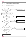
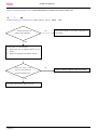
Trouble Shooting
★
★
■: Room temperature sensor failure
□: Heat-exchange sensor failure
■
□
whether terminal CN8 on
NO
CN8
CN8
Pull out the terminals on the indoor mainboard and
indoor PCB contact wellt?
reinsert them
YES
Pull the sensor out of the mainboard
1)
Measure the value of resistance Between its two
jumpers
2)
Measure the temperature at the room temperature
sensing head.
Check the value of the
NO
Sensor is broken,replace it with new sensor
sensor to see whether the
sensor is damaged or not?
YES
The indoor PCB is broken, replace with new indoor PCB
28
H2SM-14/18C03/R2
★
□
★: Indoor EEPROM error: Replace the PCB of indoor unit
■
□
★:Indoor fan motor malfunction
whether terminal CN7
YES
Pull out and reinsert the terminals
and CN11 on indoor PCB
well inserted or not?
NO
Electrify the machine again and turn it on in the cooling
operation, Measure voltage between the
positions 1 ( red
wire) and 5( black wire) of Terminal CN1 on the indoor PCB
NO
. the voltage is about
the indoor pcb is damaged and need replace
90-200vac
Yes
NO
check whether motor
can run when
the indoor motor is damaged and need
replace
turn on the unit
Yes
When motor is running Measure
whether
there
pulse(0-5VDC)
is
voltage
between
NO
the
the indoor motor is damaged and need
positions 2 (middle wire) and
replace
3( black wire) of Terminal CN7
on the indoor PCB
the indoor pcb is damaged and need replace
29
H2SM-14/18C03/R2
LED1 of outdoor pcb flashes once: outdoor EEPROM error: Replace the PCB of outdoor unit,
★
□
■
LED1of outdoor pcb
flashes twice: Outdoor ambient Sensor failure
whether terminal CN1 on
NO
CN1,
Pull out the terminals on the outdoor mainboard and
outdoor PCB contact well?
reinsert them
YES
Pull the sensor out of the mainboard
3)
Measure the value of resistance Between its two
jumpers
4)
Measure the temperature of Outdoor
ambient
Check the value of the
NO
Sensor is broken,replace it with new sensor
sensor to see whether the
sensor is damaged or not?
YES
The outdoor PCB is broken, replace a new one
30
H2SM-14/18C03/R2
■
■
★ :Communication fault between indoor and outdoor system
Yes
Check whether the linking cable
between the indoor and outdoor
Reconnect the linking cable;
is not well connected
NO
Yes
If unit A have error , please turn
please
reverse
the
outdoor
on A and B both,check whether B
connecting wires A(C) and B (C)
is fine
between unit A and B,
if A is error and B is fine, indoor
unit A PCB is damaged
NO
YES
please
check
whether
the
reconnect the L and N wires
connecting of L or N is reversed of
the two
if A is fine and B has error,the
outdoor unit main PCB is damaged
units
NO
YES
Check whether the LED1
on the outdoor pcb
the outdoor PCB is damaged
is on
NO
check
whether
CN7 in
the voltage of
NO
check whether fuse of outdoor
outdoor pcb is about
YES
pcb is broken
198-253VAC
reaplace
the fuse with
T3.15A 250V
NO
YES
check whether the wire from
terminal block to out pcb is well
connected
check
whether
the voltage of
CN4
in
outdoor pcb is about 12VAC
NO
the transformer is
bad
YES
the outdoor PCB is damaged
31
NO
Reconnect
wire
the
linking
H2SM-14/18C03/R2
LED1 of outdoor pcb
flashes 5 or 9 times outdoor unit A or B’s coi sensor
whether terminal CN2 on
NO
failure
CN2
Pull out the terminals on the outdoor mainboard and
outdoor PCB contact well?
reinsert them
YES
Pull the sensor out of the mainboard
5)
Measure the value of resistance Between its two
jumpers
6)
Measure the temperature of
outdoor unit A or
B’s coi
Check the value of the
NO
Sensor is broken,replace it with new sensor
sensor to see whether the
sensor is damaged or not?
YES
The outdoor PCB is broken, replace a new one
32
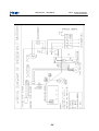
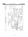
Domestic Air Conditioner
WIRING DIAGRAM
33
Model: H2SM-14HC03/R2
H2SM-18HC03/R2
Domestic Air Conditioner
38
349
34
Model: H2SM-14HC03/R2
H2SM-18HC03/R2
Domestic Air Conditioner
40
35
Model: H2SM-14HC03/R2
H2SM-18HC03/R2
Domestic Air Conditioner
Model: H2SM-14HC03/R2
H2SM-18HC03/R2
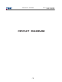
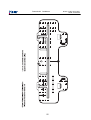
CIRCUIT DIAGRAM
436
H2SM-14/18C03/R2
1
2
3
4
+5
BEEP-PKM13EPY-4002
BUZ1
+12v
5
6
8
7
+5
C29
104/50v R15
10k
R16
10k
R65
R11
10k
R17
10k
10K
R13 10K
D
10K
+5
2
1
CN9
R49
100
R12
R27 10K
R66 27
Q11
2SC2412 C36
Q4
2SC2412
10K
E15
1N4007
+12
D1-D4
D5
CN3
CN2
C35
104
470UF/16V
FUSE
3.15A
104/275V 561K
IN4007
C17
104
C12
102
R59
4.7K
R31
IC9
7805
R18
4.7k
103/50v
Q1
2SC2412
R30
+12V
+5
Q5
2SC2412
D
CN4
E8
2200UF/25V
+12
E9
T1
C40
0-171825-3 RTB-1.5-2P
C42
104/50V
Z1
B2P3-VH-A
100u/25v
10K
+5
+5
R52
10K
10K
48
PTH1/KBD3
49
PTH1/KBD4
PTF4/TBCH0
3.3K
03
R51
C13
104
RST
21
VSS
GND
45
AVSS/VRE
GND
56
VSSA
GND
60
PTC0
10
PTF7
57
R50 51K
CN7
R14 1K
C43
103
CN6
C16
102
220V-L
+5V
Q3
C39
CN1
1
2
3
2UF 450V
R42 C24
220V-N
R4
R38
R39
IC10
0.01u/275V
L1
R40
+5
R93
TLP3526
+5
R20 10K
R73
27
R58 10K
28
29
D
C
B
A
30
31
32
33
10K
SW3
5v
Q10
R91
4.7K
8
7
6
5
4
3
2
1
R89 22K
2SC2412
PTE6/MOSI
PTG2/KBD2
PTE3/TACH1
PTE4/SS
PTE5/MISO
PTG0/KBD0
PTG1/KBD1
38
50
PTD4
44
47
46
43
42
41
40
39
8M
9
10
11
12
13
14
15
16
CN5
104/50V
R82
330 1/4W
Q9
2SC2412
C22
R85 2.2K 1/4W
102 R86
10K 1/4W
+5
6
1
3
C38
61
102/50V
C25
53
102/50V
SJ20-07WX
C27
52
102/50V
E13
100u/25v
C26
51
102/50V
330K 1/4W
5
2
2.2k 1/4W
4
+5
1N4007
1
CON5
+5
IC12
1
103/50VC49 R83
2
3
C6
1N4007
D6
IC14
TLP371
R80
R47 560 1/4W
D8
4
C7
TLP421
B
N
2.2K
LED1
R84 6.8K 2W
01
R26
10K
R46
C15
102
34
+5V
1K
5v
GREEN
R7 10K
R8 10K
5v
IC2
5
SDA
6
SCL
7
8 24C02
C14
104
SW2
4
3
2
1
ZJ1
R92
10K
CON1(red)
+12
1
RLS4148
2
C
R81
D7
1
+5V
+5V
C47
A
4
5
37
6
RL1
JQ1A-12V
A
CON2(white)
1
.
5
4
3
2
1
CN13
1
2
3
4
5
6
7
10K 1/4W
104
R24
10K
R32
10K
10K
4.7UF/50V
+5
R87
+5
PTC4
MC68HC908AB32
R25
C3
103
C4
19
PTD3
PTD2
PTD1
PTD0
PTB7/ATD7
PTD6/ATD6
PTB5/ATD5
PTB0/ATD0
2003
104
E6
1
2
3
4
R53 1K
R88 560
XT1
55
54
VDDAREF
PA0
PA1
PA2
PA3
PA4
PA5
PA6
PA7
PTB4
3.3K 1%
4.7UF/50V
R70 560
R71 560
R72 560
PTE7/SPSCK20
06
PTF2/TBCH2 05
PTF1/TACH3
IC4
C19
+12
OSC2
VREFH
VDDA
R21 10K
26
125uH
20K 1%
R35
E7
R69 10K
R68 10K
R67 10K
R1
1M
35 PTB1/ATD1
10K
R57
PTE2/TACH0
25
16
17
18
23
10K 24
R64
+5V
15
R44 1K
+5
NC
PTE0/TXD
PTE1/RXD
R34
C9
102
C41
102
04
61
64
63
62
53
52
51
59
CGMXFC
13
14
10K
4.7K
10K
4.7K
2SC2412
220
120 1W
PTF0/TACH2
PTC1
PTC5
PTC3
PTC2/MCLK
PTD7
PTD6/TACLK
PTD5
OSC1
58
4
3
2
1
+5V
B
R45 1K
36
37
C10
102
R36 1K
+5
1
2
3
09
+5V
R37 10K
+5V
CN8
+5
PTB2/ATD2
PTB3/ATD3
08
C2 104
E4
100u/16v
1
R43
3.3K
10K
C28
104/50V
E5
100u/16v
220V-N
C1
102
C
R5
Q8
2SB1197
C18
104/50V
PTF5
PTF6
104/50V
R29
R54
680
22
103/50V
+5
VDD
PTF3/TBCH3
R6
R97
R95
R96
R98
R33
+5V
IRQ
10K
10K
10K
10K
10K
10K
11
12
R3 1K
R10 10K
07
1
R2 10K
02
4.7K
3
SW1
R41 1K
R9
2
C5 102
2
1
R28 1K
Q2
2SC2412
7
8
4338
Domestic Air Conditioner
Model: H2SM-14HC03/R2
H2SM-18HC03/R2
TROUBLE SHOOTING
4439
Model: H2SM-14HC03/R2
H2SM-18HC03/R2
Domestic Air Conditioner
50
40
Domestic Air Conditioner
Model: H2SM-14HC03/R2
H2SM-18HC03/R2
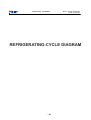
REFRIGERATING-CYCLE DIAGRAM
4641
Model: H2SM-14HC03/R2
H2SM-18HC03/R2
Domestic Air Conditioner
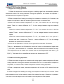
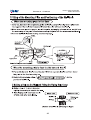
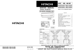
Warning and cautions :
1.1 The multi-mounted split unit adopts double separated cooling systems (A and B) that are not connected together. If
the refrigerant leaks, the leaking system of them must be determined. So we can solute the abnormality. And refill the
system that lacks refrigerant. It will influence the eff ect if the A and B systems ar e wr ongly estimated.
1.2 The maximum length of single connecting pipe is 7m. And the units c an't run normally if the pipe is over required
length.
1.3 Fill refrigerant in accordance w ith the diagram below if the connec ting pipe is over 5m.
Length
5HIULJHUDQWFKDUJH
5m
12
7m
J
---
9DFXXPSXPSLQJRIWKHV\VWHP
9DFXXPSXPSLQJLVWRPDLQO\GUDZRXWUHVLGXDODLUDQGZDWHULQWKHDLUFRQGLWLRQHUUHIULJHUDQWV\VW HP
*HQHUDOO\YDFXXPSXPSLVFRQQHFWHGDWWKHSURFHVVLQJSRUWRIWKHZD\VWRSYDOYHLQWKHRXWGRRUXQLW
7KHV\VWHPYDFXXPGHJUHHLVUHTXLUHGWREHEHORZ3D
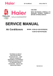
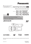
5HIULJHUDWLQJF\FOHGLDJUDP
Capillary
Capillary tube
Outdoor unit
Heat exchanger
Capillary tube
Capillary
B Compressor
B 4-way valve
A 4-way valve
A Compressor
42
tube
2- way valve
2- way valve
tube
A indoor unit
Heat exchanger
B indoor unit
Heat exchanger
3- way valve
3- way valve
Cooling
Heating
Domestic Air Conditioner
Model: H2SM-14HC03/R2
H2SM-18HC03/R2
NOISE LEVEL TEST CHART
& AIR VELOCITY DISTRIBUTION
4843
Model: H2SM-14HC03/R2
H2SM-18HC03/R2
Domestic Air Conditioner
G%$
G%$
LQGRRU
XQLW
RXWGRRU
XQLW
+]
+]
+]
+]
+]
49
44
+]
+]
+]
Domestic Air Conditioner
B.Air velocity distribution
45
Model: H2SM-14HC03/R2
H2SM-18HC03/R2
Domestic Air Conditioner
Model: H2SM-14HC03/R2
H2SM-18HC03/R2
INSTALLATION & MAINTENANCE
46
Domestic Air Conditioner
47
Model: H2SM-14HC03/R2
H2SM-18HC03/R2
Domestic Air Conditioner
48
Model: H2SM-14HC03/R2
H2SM-18HC03/R2
Domestic Air Conditioner
49
Model: H2SM-14HC03/R2
H2SM-18HC03/R2
Domestic Air Conditioner
50
Model: H2SM-14HC03/R2
H2SM-18HC03/R2
Model: H2SM-14HC03/R2
H2SM-18HC03/R2
Domestic Air Conditioner
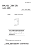
1
YEL/GRN
WHT
2
3(C)
RED
BLK
1
2
3
RED
BLK
WHT
YEL/GRN
YEL/GRN
1
Indoor unit A
WHT
2
3(C)
RED
BLK
1
2
3
BLK
RED
YEL/GRN
{
BLU
N
POWER
Indoor unit B
BRN
L
WHT
YEL/GRN
Outdoor unit
51
Domestic Air Conditioner
52
Model: H2SM-14HC03/R2
H2SM-18HC03/R2
Domestic Air Conditioner
53
Model: H2SM-14HC03/R2
H2SM-18HC03/R2
Domestic Air Conditioner
54
Model: H2SM-14HC03/R2
H2SM-18HC03/R2
Domestic Air Conditioner
55
Model: H2SM-14HC03/R2
H2SM-18HC03/R2