1
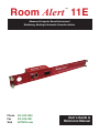
Room Alert 11E ™ Advanced Computer Room Environment Monitoring, Alerting & Automatic Corrective Action Phone Fax Webal 401.628.1600 401.628.1601 AVTECH.com User’s Guide & Reference Manual 090415.01 Copyright Information Copyright 1988-2009 AVTECH Software Inc. All Rights Reserved. No part of this book may be used or reproduced for commercial benefit in any form or by any means, or stored in a database or retrieval system, without prior written permission of AVTECH Software Inc., except in the case of brief quotations embodied in articles and reviews. Making copies of any part of this book for any purpose other than your individual use is a violation of United States copyright laws and international treaty provisions. For information or additional copies, contact AVTECH Software Inc., as directed below. Printed in the United States of America. Warning and Disclaimer This publication is shipped as is, without warranty of any kind, either express or implied. While every precaution has been taken in the preparation of this publication, the publisher and authors assume no responsibility for errors or omissions. Neither is any liability assumed for damages resulting from the use of the information or instructions contained herein. It is further stated that the publisher and authors are not responsible for any damage or loss to your data or equipment that may result directly or indirectly from your use of this publication and the related hardware & software. Nothing on the AVTECH Install & Update CD or documentation shall be construed as conferring any license under any of the AVTECH Software (AVTECH) or any third party’s intellectual property rights, whether by estoppel, implication, or otherwise. Trademark Acknowledgements AlertScript, AVTECH, the AVTECH Logo, AVTECH Software, the AVTECH System Manager Character, AVTECH.com, AVTECHSoftware.com, Environment Alarm, “Environment Monitoring Made Easy!”, EnvironmentMonitor.com, “IT Environment Monitoring Made Easy!”, MUPS, “Network-Wide Monitoring Made Easy!”, Page Command, PageR, PageR Data Center, PageR Enterprise, PagerEnterprise.com, Device Discovery, Device ManageR, “Protect Your IT Environment... Don’t Wait Until It’s Too Late!”, Room Alert, Room Alert PLUS, Room Alert RPC, Room Alert Signal Tower, Signal Tower, RoomAlert.com, “System Monitoring Made Easy!”, TemPageR, TemPageR.com, “Temperature Monitoring Made Easy!”, WiSH and WiSPR, are trademarks or registered trademarks of AVTECH Software Inc. Any other trademarks, product or company names mentioned herein are the property of their respective owners and used strictly for the purpose of identifying compatibility. AVTECH Software Inc. cannot attest to the accuracy of any other organization’s ownership claim to a trademark and use of any trademark in this publication should not be regarded as affecting the validity of any trademark or service mark. Special Thanks We would like to recognize field test participants, our inhouse support staff and the entire software & hardware development teams for their contributions and assistance in completing this manual. Sales, Support & Contact Information To receive further information or assistance regarding this publication, or any AVTECH product or service, please contact: Headquarters AVTECH Software Inc. Email [email protected] 16 Cutler Street [email protected] Warren, RI 02885 USA [email protected] Phone 401.628.1600 Web Sales 888.220.6700 Fax 401.628.1601 AVTECH.com EnvironmentMonitor.com PagerEnterprise.com RoomAlert.com TemPageR.com Room Alert 11E Table of Contents Table Of Contents Introduction....................................................................................................................1 What Room Alert 11E Is.............................................................................................................................1 Benefits Of Using Room Alert 11E.............................................................................................................2 Installation......................................................................................................................3 Package Contents........................................................................................................................................3 Room Alert 11E ID Box..............................................................................................................................3 Step 1: Install The AVTECH Device Discovery Utility..............................................................................4 Step 2: Install The Room Alert 11E ID Box...............................................................................................4 Step 3: Discovery And Network Settings...................................................................................................5 Static-Only Networks..............................................................................................................................7 Device Not Found Or Invalid IP Address...............................................................................................8 Step 4: Connect Sensors And Accessories..................................................................................................8 Step 5: Check Room Alert 11E Firmware Version.....................................................................................9 Configuration And Setup Screens.............................................................................10 Alert Methods............................................................................................................................................10 Email.........................................................................................................................................................10 Initial Email Setup.................................................................................................................................11 Test Email..............................................................................................................................................11 Email-To-SMS...........................................................................................................................................11 SNMP.........................................................................................................................................................12 SNMP Queries (SNMP Get)......................................................................................................................13 SNMP Traps..............................................................................................................................................13 Monitoring With PageR Enterprise (PageR).............................................................................................13 Alert Thresholds........................................................................................................................................13 Digital Sensors...........................................................................................................................................14 Switch Sensors...........................................................................................................................................15 External Sensor Options.............................................................................................16 Digital Temperature Sensor.......................................................................................................................16 Digital Temperature/Humidity Sensor.......................................................................................................16 Digital Power Sensor.................................................................................................................................16 Flood Sensor..............................................................................................................................................16 Sound, Light & Entry Sensor.....................................................................................................................16 Motion Sensor............................................................................................................................................17 Power Sensor.............................................................................................................................................17 AVTECH Software Inc. i Room Alert 11E Table of Contents Smoke Sensor............................................................................................................................................17 Air Flow Sensor.........................................................................................................................................17 Room Entry Sensor....................................................................................................................................17 Panic Button..............................................................................................................................................17 Dry Contacts..............................................................................................................................................17 Additional Screens And Interfaces.............................................................................18 Network.....................................................................................................................................................18 Security......................................................................................................................................................18 Advanced...................................................................................................................................................19 Using Trace Output....................................................................................................................................20 Help...........................................................................................................................................................21 About.........................................................................................................................................................21 Web Interface.............................................................................................................................................21 Advanced Topics.........................................................................................................23 Upgrading Firmware.................................................................................................................................23 Reset Factory Default Settings..................................................................................................................23 Unit Accessible Although Not Discoverable.............................................................................................23 Performing A Firmware Recovery.............................................................................................................24 Included With All Room Alert & TemPageR Models... PageR Enterprise Network-Wide Server, Device & Event Monitoring, Alerting & Automatic Corrective Action ii AVTECH Software Inc. Room Alert 11E Introduction Introduction What Room Alert 11E Is The Room Alert 11E ID Box is one of AVTECH Software’s (AVTECH) hardware solutions for ‘Advanced Computer Room Environment Monitoring, Alerting & Automatic Corrective Action’. It is designed specifically to monitor 1-3 digital temperature or digital temperature/humidity sensors and 8 switch sensors in distributed locations spanning several hundred feet. The Room Alert 11E additionally allows unlimited alert notifications via email to devices like computers, mobile phones, BlackBerrys, iPhones, pagers and PDAs. Users can set up thresholds for temperatures that are rising or falling and easily work with Room Alert 11E through their favorite web browser. Status of attached sensors for Power, Smoke, Flood, Air Flow and more can be viewed in real-time. Because each Room Alert 11E ID Box is SNMP enabled, they can easily be monitored by software applications like Device ManageR, PageR Enterprise (PageR), Tivoli, OpenView, Unicenter, Big Brother, Nagios, What’s Up Gold, SolarWinds and others. Room Alert 11E is designed to easily work with PageR Enterprise software which is included and will significantly enhance the alert notification capabilities to allow notification to individuals, groups, hierarchies, different people for different sensors/locations, and different people for different times of the day. With PageR, alert notification methods can be expanded to include email, Simple Network Paging Protocol (SNPP), dialout paging (TAP or UCP), web page update, logfile update, pop-up broadcast message, MSN Messenger, audio alert, spoken English text, fax and more. PageR will also allow automatic corrective actions both on alarm start and resolution. This means that users have the ability to run commands, start executables, run JavaScripts, run Visual Basic (VB) scripts, and the like. If you have not looked at PageR before, take a look because it truly is one of the easiest and most powerful products to use in monitoring servers, devices and events network-wide, regardless of the various operating systems that may be in use across your organization’s network. It’s included for FREE. AVTECH’s Device ManageR software is also included FREE and is designed to set up, monitor and manage unlimited numbers of Room Alert and/or TemPageR units across your network. Device ManageR will log all sensor data and allows graphing, Pings, firmware updating and much more. Room Alert 11E is a member of AVTECH’s Room Alert product line. There are several powerful Room Alert models designed to monitor environmental conditions in the data center like temperature, humidity, main / UPS power, flood / water, smoke / fire, entry / intruder, air flow and more. All Room Alert models come with a license to run PageR and include a printed copy of the ‘Getting Started With PageR Enterprise’ manual. To learn more about AVTECH’s Room Alert, TemPageR, PageR or Device ManageR products, visit AVTECH.com. To order AVTECH products, visit EnvironmentMonitor.com or call 888.220.6700 / 401.628.1600. AVTECH products are also available through your favorite reseller, just ask them to contact us on your behalf. AVTECH Software Inc. Introduction Room Alert 11E Benefits Of Using Room Alert 11E Know immediately when important or critical temperature changes and extremes occur within a computer room, data center or other facility that could lead to expensive downtime, damaged equipment, lost worker productivity or denied server access. Providing early warnings about situations that could damage hardware, threaten uptime or block system access allows staff and management to take actions that can avoid or minimize an events’ impact on servers, the network, users, recovery insurance and the emergency IT budget. Give the IT staff and management “peace of mind” by keeping them fully informed of critical temperature changes regardless of where they are, the time of day or day of the week. Temperature extremes place an enormous stress on computer hardware and are normally caused by failure of the main air conditioning system or a loss of power. Extremes for even a short time can create major challenges for the IT staff and their budget. Room Alert 11E provides dynamic, real-time temperature monitoring of the computer room, data center or other facilities. Some customers use Room Alert 11E to monitor hospital lab refrigerators, incubators, or coolers. Restaurants use it to monitor their coolers, dining room and lounge areas. We even have people who use Room Alert 11E to monitor their personal wine cellars, remote cabins in New England, and water pipes in homes during Winter months. Monitoring of digital temperatures is possible at up to three (3) locations for each Room Alert 11E box, two (2) of these can be as far as 100 feet away from the Room Alert 11E box. Monitoring of switch sensors such as main / UPS power, flood / water, smoke / fire, air flow, motion, intruder / entry, panic buttons and more is possible at eight (8) locations for each Room Alert 11E box and can be as far as 900 feet away from the Room Alert 11E box. Notification to an unlimited number of individuals or groups, at unlimited temperature thresholds (too high or too low), and by notification to each users’ device of choice when used with PageR Enterprise. Notifications can be sent by email to computers, mobile phones, pagers, PDAs, web pages and more. AVTECH’s Device ManageR software will enhance Room Alert 11E’s capabilities by allowing logging of sensor data over the short or long term for tracking or identification of critical times of the day where environment conditions may change to consistently cause problems. Device ManageR can also graph sensor data for immediate analysis. Sensor data can be exported in Excel format by clicking a single button. Charts, graphs and reports can be prepared in other applications for presentation to management or periodic review by staff. This can be useful for justification of new air conditioning equipment, modifying the data center layout or justifying changes like the location of primary servers or the data center. AVTECH Software Inc. Room Alert 11E Installation Installation The initial installation of the Room Alert 11E can be completed quickly and easily provided the instructions below are followed with detail and care. Before beginning, please lay out the contents of the Room Alert 11E package so that the components can all be located and accessed with ease. Package Contents The main components included with the standard (default) Room Alert 11E package include: • • • • • • • • • One (1) Room Alert 11E ID Box (1U 19˝ Mounting Bracket Is Included w/Room Alert 11ER) One (1) Ethernet Cable (10’ length, red) One (1) AVTECH 5V 1A Power Adapter (110-240V, 50-60Hz, RoHS) One (1) External Digital Temperature/Humidity Sensor One (1) External Main Power Sensor One (1) Room Alert 11E User’s Guide & Reference Manual (you’re reading it) One (1) Getting Started With PageR Enterprise manual One (1) AVTECH Install & Update CD One (1) Package Of Literature & Additional Information NOTE: Some of the components arriving with this package may be individually wrapped and contain additional supporting components. Please remember to keep these components together as they will be required for proper setup. If you received additional components (i.e. like additional sensors) that are not mentioned above, instructional material explaining the proper setup of that component should be included with it. If you cannot find the proper instructional materials, check the included CD or ‘Support’ and ‘Downloads’ sections of the AVTECH.com website for any appropriate installation or application note that will instruct you on the proper installation and use of that component. Install those components after the Room Alert 11E setup is completed. Room Alert 11E ID Box The graphics below identify the primary components of the Room Alert 11E ID box that are visible on the front and rear panels. Front View (Room Alert 11E ID Box) A C B A. Main Power Port — Connect the ‘AVTECH 5V 1A Power Adapter’ to this port to power the Room Alert 11E unit. Do not use any other power adapter or it could damage the unit. B. Network Port — Attach the Room Alert 11E unit to the network by plugging the Ethernet cable into this port and then connecting the other end to the network. The left LED above the ‘Network’ port indicates Link status and should light up and remain a solid green or orange color. The right LED above the ‘Network’ port indicates Activity status and should blink with network activity on the port. The color of this LED can be green or orange as well. When the device AVTECH Software Inc. Installation Room Alert 11E reboots, the Link LED will turn on and off several times. If the Link LED remains unlit and the Activity LED is blinking orange, please refer to the ‘Performing Firmware Recovery’ section of the ‘Advanced Topics’ chapter. This is an RJ-45 port. C. External Environment Sensor (Digital Sensor) — AVTECH’s Digital Temperature and Digital Temperature/Humidity Sensors can be connected to these sensor channels. This is an RJ-11 port. Back View (Room Alert 11E ID Box) D D. Switch Sensor Contact Sets — Connect any AVTECH switch-based environment sensor to a set of sensor contacts for monitoring by the Room Alert 11E unit. Any switch sensor device with a set of voltage-free dry contacts can be attached to a set of sensor contacts. AVTECH has many sensors available for monitoring environment and other conditions. Step 1: Install The AVTECH Device Discovery Utility The AVTECH Device Discovery Utility is used to initially discover the Room Alert 11E after it is connected to your network. The Device Discovery Utility can be installed from the AVTECH Install & Update CD or downloaded from the ‘Downloads’ section of the AVTECH.com website. Install this utility on a Windows-based computer that is located on the same network that the Room Alert 11E unit will be connected to. Install this now and we will come back to the Device Discovery Utility in a later step. Step 2: Install The Room Alert 11E ID Box The Room Alert 11E must be connected in the following order for initial configuration and discovery on the network to be successful. Locate the Ethernet cable included with your package and connect one end to the ‘Network’ port on the front of the Room Alert 11E unit. Connect the other end of the Ethernet cable to an open port on the switch or router that will give the Room Alert 11E unit access to your network. Next, locate the ‘AVTECH 5V 1A Power Adapter’ and plug it into a surge protected UPS power source. This will allow alert notifications even after a complete power loss. NOTE: It is recommended that the Room Alert 11E unit be plugged into a UPS or AVTECH’s Mini UPS & Power Sensor (MUPS). Attach the other end of the power adapter to the ‘Power’ port on the Room Alert 11E unit only if the Room Alert 11E unit is already connected to the network. Be sure to remove the sticker over the ‘Power’ port before attaching the ‘AVTECH 5V 1A Power Adapter’ to the Room Alert 11E unit. AVTECH Software Inc. Room Alert 11E Installation IMPORTANT NOTE: DO NOT CONNECT POWER to the Room Alert 11E unit during the initial setup UNTIL AFTER you have connected it to your network as described above or it will cause problems automatically assigning the initial IP address. Once the network and power connections have been completed, verify that the LED located on the top-left side of the network jack lights up indicating power and network connectivity. Step 3: Discovery And Network Settings Once the Room Alert 11E unit has been properly installed according to Step 2 above, open the AVTECH Device Discovery Utility and click the ‘Search’ button. The AVTECH Device Discovery Utility will attempt to discover the Room Alert 11E unit connected to your network by sending out a UDP broadcast on UDP port 30718. NOTE: If there are multiple Ethernet adapters on the computer that the AVTECH Device Discovery Utility is installed on, a dialog will display asking for the proper network to perform the search on. Make the correct selection and then continue. The Room Alert 11E unit is initially set to obtain an IP address automatically using DHCP. If you do not have DHCP on your network, please see the ‘Static-Only Networks’ section below. The Room Alert 11E unit connected to your network should appear in the AVTECH Device Discovery Utility window as illustrated above. This will normally take just a few seconds. If the IP address displayed is ‘169.xxx. xxx.xxx’ and the ‘Name’ is displayed as ‘Unknown’ or if the Room Alert 11E unit was not found, please see the ‘Device Not Found Or Invalid IP Address’ subsection below before continuing. Once the Room Alert 11E unit is displayed, select it from the list to perform an action on it. Selecting multiple units will cause the action selected to be performed on multiple units (i.e. all selected units) simultaneously. AVTECH Software Inc. Installation Room Alert 11E The ‘Set IP’ button is used to assign a static IP address, gateway IP address, subnet mask and DNS server IP address or to set the Room Alert 11E unit back to DHCP (0.0.0.0). If the ‘Set IP’ button is pressed without a specific Room Alert 11E unit selected in the AVTECH Device Discovery Utility, a prompt will display asking for the MAC address of the unit. This option can be used in conjunction with the MAC address listed on the bottom of the Room Alert 11E unit to attempt IP address assignment of a unit that cannot be located or has previously been obtained or assigned an incorrect IP address. The ‘Settings’ button opens the default web browser and displays the ‘Settings’ screen of the Room Alert 11E web interface. The ‘Settings’ screen allows for further configuration of the Room Alert 11E unit and is where alerts, email, SNMP and other settings are configured. The ‘Web’ button displays the main ‘Status’ screen of the Room Alert 11E web interface which shows current sensor data and alarm status in the default web browser for the system you are using. Be sure to bookmark the link that loads for quick and easy reference in the future. The ‘Update’ button initiates the firmware upgrade process of the AVTECH Device Discovery Utility. If a Room Alert 11E unit is not selected before left clicking this button, a dialog will display asking for the IP address of the unit to upload firmware to. Please see the ‘Upgrading Firmware’ section of the ‘Advanced Topics’ chapter for important instructions on the ‘Update’ feature. The AVTECH Device Discovery Utility offers additional features accessible via a right click context menu. This menu is accessible only when a located Room Alert 11E unit has been selected and the right mouse button has been clicked. These menu options are described below. The ‘Synchronize Time’ option instructs the Room Alert 11E unit to synchronize with the time server specified in the ‘Time Server IP’ field on the ‘Advanced’ tab of the ‘Settings’ screen. The time displayed on the Room Alert 11E ‘Status’ screen and included in email alert notifications can only be updated by linking with a network time server (NTP) on UDP port 123. If a time server is not available on your network and access to a time server on the internet is not possible, AVTECH has various help files available that explain how to configure a computer on the local network to act as a time server for other devices. Visit AVTECH.com to learn more and see AVTECH’s Frequently Asked Questions (FAQs). The ‘Save Settings’ feature can be used to download the current configuration settings on a Room Alert 11E unit for backup purposes. This feature can also be used to quickly configure multiple Room Alert 11E units by configuring one unit, selecting it, clicking the ‘Save Settings’ option, then selecting multiple units and clicking the ‘Restore Settings’ option. AVTECH Software Inc. Room Alert 11E Installation The ‘Restore Settings’ feature is used to restore a saved configuration created using the ‘Save Settings’ feature to one or multiple Room Alert 11E units. When selected, the user will need to select from a previously saved ‘.bak’ file located in the ‘log’ folder of the ‘AVTECH Device Discovery Utility’ directory in order to restore or update the settings on the Room Alert 11E unit(s). Static-Only Networks If the network that the Room Alert 11E unit will be connected to does not have automatic DHCP IP address assignment, the Room Alert 11E unit will default to a ‘169.xxx.xxx.xxx’ IP address. The AVTECH Device Discovery may or may not be able to discover your unit when it has obtained a ‘169 xxx.xxx.xxx’ IP address, depending on various network conditions. Follow the steps below to assign an IP address to the Room Alert 11E unit that will be appropriate for your network. 1. Restart the AVTECH Device Discovery Utility and click the ‘Set IP’ button. 2. Click ‘Ok’ on the first dialog that displays and enter the Room Alert 11E MAC address when prompted. The MAC address is listed on the label located on the bottom of the Room Alert 11E 3. Enter a valid static IP address for the current location of the Room Alert 11E unit when prompted. NOTE: If the Room Alert 11E unit is later relocated outside of the current subnet, you will need to reset the IP address in order to see and work with the Room Alert 11E unit. If the Room Alert 11E unit is still not discovered or the IP address is not updated, continue with steps 4-6. 4. Locate a cross-over Ethernet cable or spare hub and connect it to the computer being used. Connect the Room Alert 11E to the other end of the cross-over Ethernet cable or directly to the hub. 5. Assign static IP settings to the computer being used. If the ‘Search’ button is pressed after doing so, the Room Alert 11E unit should be discoverable. If it is not, be sure that there are no applications on the computer being used that are blocking traffic sent to or from the AVTECH Device Discovery Utility (i.e. software firewalls, anti-virus applications, etc.) 6. Repeat steps 1-3 above although enter a static IP address in step 3 that has the same first three octets as the static IP address assigned to the computer (i.e. IP address of computer: 192.168.2.3, IP address of Room Alert 11E: 192.168.2.4). If the IP address of the Room Alert 11E unit is still not updated, continue with steps 7-9. 7. Assign static IP settings to the computer being used that match the IP address of the Room Alert 11E (i.e. IP address of Room Alert 11E: 169.254.10.122, IP address of computer: 169.254.10.123). AVTECH Software Inc. Installation Room Alert 11E 8. Click the ‘Search’ button in the AVTECH Device Discovery Utility and select the Room Alert 11E unit when discovered. 9. Click the ‘Set IP’ button and enter a valid IP address for the location on the network where the Room Alert 11E unit will be located. If the IP address does not update, access the ‘Settings’ screen of the Room Alert 11E unit and enter the IP address settings on the ‘Network’ tab. After doing so, click the ‘Save Settings’ button, wait 10 seconds and re-attach the Room Alert 11E unit to the network. Device Not Found Or Invalid IP Address If the Room Alert 11E is not discovered by the AVTECH Device Discovery Utility, the network may be blocking UDP broadcast packets on port 30718. Even if the Room Alert 11E obtains a valid IP address, this can prevent the Room Alert 11E unit from being discovered. To resolve this issue, check the DHCP server for the MAC address listed on the label located on the bottom of the Room Alert 11E unit. If this is not possible or if there is not an entry in the DHCP server, follow the instructions listed under the ‘Static-Only Networks’ subsection above. If the Room Alert 11E unit is discovered although has a ‘169.xxx.xxx.xxx’ IP address, the Room Alert 11E unit may not have been connected properly or DHCP assignment may currently be getting blocked. In either case, follow the instructions listed in the ‘Static-Only Networks’ subsection above. NOTE: If the instructions provided do not allow configuration of the Room Alert 11E unit, please initiate a Live Chat technical support request on AVTECH.com or send an email support request to [email protected]. Step 4: Connect Sensors And Accessories The graphics below identify the connection ports and channels of the Room Alert 11E ID box that are visible on the front and rear panels. Use these to connect the appropriate sensors and accessories. Front View (Room Alert 11E ID Box) A A. Digital Temperature/Humidity Sensors — Connect the included AVTECH Digital Temperature/Humidity Sensor to one of the External Environment Sensor Channels shown above (A). The Digital Temperature/Humidity Sensor provides a real-time digital temperature and humidity reads at the location of the probe. Position the sensor in the desired location, running the sensor cable back to the Room Alert 11E ID box. DO NOT remove the blue plastic cap from the tip of the sensor. AVTECH Software Inc. Room Alert 11E Installation Back View (Room Alert 11E ID Box) B B. Switch Sensors — Connect the optional Switch Sensors to one of the Switch Sensor Contact Set (B). Position the sensor in the desired location, running the sensor cable back to the Room Alert 11E ID box. This is an instant ‘plug & play’ sensor that connects to one of the switch sensor contact sets via a low voltage 2-wire cable. Step 5: Check Room Alert 11E Firmware Version Open the AVTECH Device Discovery Utility and click the ‘Search’ button. When the Room Alert 11E unit is located, select it and click the ‘Web’ button. If you are unable to locate your Room Alert 11E unit because UDP broadcast packets are blocked on your network, simply type the IP address of the Room Alert 11E unit in the location bar of a web browser. NOTE: If the ‘Status’ screen does not load sensor data, be sure that a proxy or Microsoft ISA (Internet Security and Acceleration) server is not blocking traffic to or from the Room Alert 11E unit. After the ‘Status’ screen has loaded and is fully displayed, click the ‘Room Alert 11E vX.X.X’ link in the top right hand corner. If the pop-up that loads says a more current version is available, then follow the instructions in the ‘Upgrading Firmware’ section of the ‘Advanced Topics’ chapter of this manual. AVTECH Software Inc. Configuration & Setup Screens Room Alert 11E Configuration And Setup Screens Alert Methods The Room Alert 11E unit can send alert notifications via email and email-to-SMS using anonymous SMTP relay and/or SNMP Traps. The Room Alert 11E unit is fully SNMP compliant and can be accessed by any application that can issue a SNMP Get request. PageR can therefore be used to perform SNMP Get requests and receive SNMP Traps. Email The ‘SMTP Email’ section displays settings to allow Room Alert 11E to send Email Alert Notifications when alert thresholds are exceeded. In order to enable email alerting from the Room Alert 11E web server interface, your mail server must have ‘SMTP Relay’ enabled for either your network or the IP address of the Room Alert 11E ID Box. Contact your Network Administrator if you need assistance in doing this. 10 AVTECH Software Inc. Room Alert 11E Configuration And Setup Screens Initial Email Setup First, check the ‘Email Enabled’ checkbox and enter the domain name or IP address of the mail server being used in the ‘Mail Server’ field on the ‘SMTP Email’ tab. Next, enter an email address in the ‘Return Address (From)’ field for an account that resides on the mail server being used. If SMTP authentication is required, check the ‘Enable Authentication’ checkbox and enter a valid username and password for the mail server. Finally, enter the email addresses to be alerted when alarms occur in the ‘Email Addresses’ field. If more than one email address is entered, use a comma (,) as the separator. Once all SMTP Email settings are configured, click the ‘Accept Changes’ button then ‘Save Settings’. NOTE: If a domain name is entered in the ‘Mail Server Address’ field, the Room Alert 11E unit must be assigned static IP settings and have a DNS server IP address set. Test Email A test email can be sent to the configured recipients using the ‘Send Test Email’ button after valid email settings have been configured and saved. If the test email is not received, check with the mail server administrator in regards to the current SMTP relay settings. The ‘Trace’ feature on the ‘Advanced’ tab of the settings is also useful for troubleshooting email and other issues. For more information, please see the ‘Advanced Settings’ section of this manual. Email-To-SMS Email alert notifications can be sent via Short Message Service (SMS) to computers, mobile phones, alphanumeric pagers and PDAs using SMS text messaging in addition to regular email. This functionality is widely supported by current mobile device service providers and is accomplished by sending email to an email address, formatted in a way defined by the service provider being used for the target mobile device. AVTECH Software Inc. 11 Configuration & Setup Screens Room Alert 11E For example, Verizon’s email address format for sending email alert to a mobile device using SMS text messaging is ‘<10 digit mobile device number>@vtext.com’ with ‘<10 digit mobile device number>’ being replaced by the area code and phone number of the mobile device without dashes, spaces or a ‘1’ in front of the area code. If the specific format for your service provider is not known, AVTECH provides a database in the ‘Support’ section of the AVTECH.com website that contains the email-to-SMS format for many available service providers. This is the largest database of this type on the web. However, if your service provider is not listed, please contact them by phone for the proper format and be sure that the mobile device being used has text messaging capability enabled. If you learn of a new or changed format, please email this with your contact information to [email protected] so we may confirm and post it online for the convenience of others. SNMP The Room Alert 11E unit is fully SNMP compliant and can be monitored by applications capable of performing an SNMP Query or Get request. The Room Alert 11E unit can also be configured to send SNMP Traps to up to three separate IP addresses when thresholds are exceeded. The bundled PageR software offers the ability to initiate SNMP Queries to and receive SNMP Traps from the Room Alert 11E unit. PageR can be used if desired, enabling advanced alerting and automatic corrective action features. If another application is used to monitor the Room Alert 11E unit, be sure to obtain the MIB files for the Room Alert 11E unit from the ‘Downloads’ section of the AVTECH.com website or the most recent AVTECH Update CD. SNMP Queries (SNMP Get) The ‘SNMP’ section displays settings allowing Room Alert 11E to respond to SNMP Query requests from network monitoring applications like PageR Enterprise, Tivoli, OpenView, Unicenter and others. Enter the ‘Community Name’ to use for accessing the SNMP data via SNMP Query for the Room Alert 11E sensors. By default, the sensor values are returned in 4-digit format since SNMP does not support floating point numbers (i.e. 78.55 would be 7855). If 2-digit format is preferred, select the ‘2-Digit SNMP Values’ checkbox. 12 AVTECH Software Inc. Room Alert 11E Configuration And Setup Screens SNMP Traps Room Alert 11E can also send SNMP Traps in response to alerts. Up to three (3) ‘Trap Send IP’ addresses can be configured on the SNMP tab and Room Alert 11E will send SNMP Traps to these systems for processing by network monitoring applications. Monitoring With PageR Enterprise (PageR) PageR is a network-wide monitoring application included (bundled) with the purchase of a Room Alert 11E unit. The license level included will depend on the quantity of units purchased and can be upgraded for greater capacity or functionality at any time by speaking to your Product Specialist. The PageR software offers the ability to monitor the Room Alert 11E unit via SNMP Query or SNMP Trap and provides more flexibility and control over when alert notifications are sent and which notification methods are available for use. PageR includes powerful features allowing unlimited alerting to individuals and groups, hierarchies, dependencies, scheduling, automatic corrective actions, and the ability to monitor any server, device or event worldwide across the network. All this is possible from a single installation, with no rules and no agents. PageR is a significant benefit of the overall Room Alert 11E package. It can be used as your primary network monitoring application or in conjunction with other monitoring applications. For instructions on configuring PageR to monitor a Room Alert 11E unit, please refer to the ‘Monitor Room Alert 11E With PageR Enterprise’ application note included with your package. This application note is also available on the AVTECH.com website in the ‘Downloads’ section. Alert Thresholds In order for alert notifications to be sent via email or SNMP Trap, alert thresholds must be configured for the sensors attached to the Room Alert 11E unit. Alert thresholds are configured on the ‘Internal’, ‘Digital’ sensors tab of the ‘Settings’ screen. Current sensor status will be displayed on the ‘Status’ screen of the Room Alert 11E web interface. The status icon displayed will be a gray circle ‘ ’ if a sensor is connected although an alert threshold is not set. If an alert threshold is set for a connected sensor and the sensor is not in an alarm state, the status icon displayed will be a green check ‘ ’. If the connected sensor is in an alarm state, the status icon displayed will be a red X ‘ ’. NOTE: The temperature sensors can be calibrated by entering correction values in the ‘Adjust’ field for each temperature sensor. Alert thresholds for switch sensors connected to the Room Alert 11E ID Box are set by specifying either ‘closed’ or ‘open’. Please refer to the documentation received for any switch sensors purchased to determine the ‘normal’ state (open or closed) of the sensor. Next, select the opposite state (i.e. not normal) to setup the Room Alert 11E ID Box to send an alert when the alarm condition exists. AVTECH Software Inc. 13 Configuration & Setup Screens Room Alert 11E Digital Sensors The alert thresholds for attached Digital Temperature Sensors are entered in the ‘Sensor # Alarm Configuration’ sections with ‘#’ representing the digital port number the sensor is connected to. Sensor 1 is the internal temperature sensor and Sensors 2 and 3 are the external temperature sensors. The sensor label for that corresponding sensor can be updated in the field below the ‘Sensor Label’. High and low thresholds for the temperature are entered in the ‘High’ and ‘Low’ columns. Temperature thresholds must be entered in the temperature scale selected on the ‘Advanced’ tab. If the sensor readings differ from a known temperature at the sensor location, they can be calibrated using the ‘Adjust’ column. Digital sensors are those that provide real-time variable status values that can be used to obtain a more definitive understanding of a current sensor’s status, allow products like Device ManageR, PageR Enterprise and other monitoring software to monitor at multiple thresholds and be logged for historical reference. These values are included within alert messages for a clearer understanding by recipients and used for trending or manipulation into graphs or charts via other applications. These sensors attach to various AVTECH hardware via RJ-11 cable to an external environment sensor channel. Current sensors providing real-time values include the AVTECH Digital Temperature Sensor and the AVTECH Digital Temperature/Humidity Sensor. 14 AVTECH Software Inc. Room Alert 11E Configuration And Setup Screens Switch Sensors Alert thresholds for switch sensors connected to the Room Alert 11E ID Box are set by specifying either ‘Closed’ or ‘Open’. Please refer to the documentation received for any switch sensors purchased to determine the ‘normal’ state (open or closed) of the sensor. Next, select the opposite state (i.e. not normal) to configure the Room Alert 11E ID Box to send an alert when the alarm condition exists. Smoke Sensor Sound, Light & Entry Sensor Power Sensor Room Entry Sensor AVTECH Software Inc. Flood Sensor Motion Sensor Air Flow Sensor Panic Button 15 External Sensor Options Room Alert 11E External Sensor Options Digital Temperature Sensor (TMP-SDT-SEN) The AVTECH Digital Temperature Sensor provides a real-time digital temperature reading at the location of the temperature probe. The temperature range is from -67° to 257° Fahrenheit and/or -55% to 125° Celsius. Accuracy is within +/- 0.5 degrees. This is an instant ‘plug & play’ sensor that connects to one of the external environment sensor channels via an RJ-11 cable. Digital Temperature/Humidity Sensor (RMA-DTH-SEN) The AVTECH Digital Temperature/Humidity Sensor provides a real-time digital temperature and digital humidity reading at the location of the sensor probe. The temperature range is from -67° to 257° Fahrenheit and/or -55% to 125° Celsius. Accuracy is within +/- 0.5 degrees. The humidity range is from 0 to 100 percent Relative Humidity (%RH). Accuracy is within +/- 3.5%. This is an instant ‘plug & play’ sensor that connects to one of the external environment sensor channels via an RJ-11 cable. Digital Power Sensor (RMA-PS2-SEN) * The AVTECH Digital Power Sensor allows real-time voltage, amperage, wattage and overall power consumption readings for the device plugged into it. Alerts can be initiated based upon consumption levels. This is an instant ‘plug & play’ sensor that connects to one of the external environment sensor channels via an RJ-11 cable. Flood Sensor (RMA-F008-SEN, RMA-F024-SEN) The AVTECH Flood Sensor is available with a standard 8´ or 24´ flood sensor cable and allows a real-time notification of flood or water leakage wherever the attached flood sensor cable is located. This is an instant ‘plug & play’ sensor that connects to one of the switch sensor contact sets via a low voltage 2-wire cable. Sound, Light & Entry Sensor (RMA-SLE-SEN) The AVTECH Sound, Light & Entry Sensor allows real-time monitoring for sound and light at the location of the sensor. This sensor also includes a set of switch sensor contacts and an AVTECH Room Entry Sensor. Each sensor can be monitored independently or an ‘any sensor’ contact set allows all sensors to be monitored via a single cable. Any switch sensor can be attached to the switch sensor contacts. This is an instant ‘plug & play’ sensor that connects to one or more of the switch sensor contact sets via a low voltage 2-wire cable. 16 AVTECH Software Inc. Room Alert 11E External Sensor Options Motion Sensor (RMA-MOT-SEN) The AVTECH Motion Sensor allows a real-time notification of movement through a zone or across a path. This is an instant ‘plug & play’ sensor that connects to one of the switch sensor contact sets via a low voltage 2-wire cable. Power Sensor (RMA-PS1-SEN) The AVTECH Power Sensor allows a real-time notification of main power status change (i.e. power going on or off). This is an instant ‘plug & play’ sensor that connects to one of the switch sensor contact sets via a low voltage 2-wire cable. Smoke Sensor (RMA-SS1-SEN) The AVTECH Smoke Sensor allows a real-time notification of the presence of smoke or fire. This is an instant ‘plug & play’ sensor that connects to one of the switch sensor contact sets via a low voltage 2-wire cable. Air Flow Sensor (RMA-AF1-SEN) The AVTECH Air Flow Sensor allows a real-time notification of air flow status change (i.e. air flow going on or off). This is an instant ‘plug & play’ sensor that connects to one of the switch sensor contact sets via a low voltage 2-wire cable. Room Entry Sensor (RMA-RE1-SEN) The AVTECH Room Entry Sensor allows a real-time notification of door or cabinet entry (i.e. door opening or closing). This is an instant ‘plug & play’ sensor that connects to one of the switch sensor contact sets via a low voltage 2-wire cable. Panic Button (RMA-PB1-SEN) The AVTECH Panic Button provides the ability to initiate a real-time notification to others via the push of a button. This is an instant ‘plug & play’ sensor that connects to one of the switch sensor contact sets via a low voltage 2-wire cable. Dry Contacts Any non-voltage, dry contact sensor can be connected to provide an immediate alert when the sensor or device changes status to go on/off, make/break, open/close. This creates an instant ‘plug & play’ sensor when connected to one of the switch sensor contact sets via a low voltage 2-wire cable. * Requires Room Alert 26W, 26WO or 24E Monitoring Units. Visit AVTECH.com for details. AVTECH Software Inc. 17 Additional Screens And Interfaces Room Alert 11E Additional Screens And Interfaces Network The ‘Network’ tab of the Room Alert 11E ‘Settings’ screen is used to update the network settings of the Room Alert 11E unit. The network settings can also be updated using the AVTECH Device Discovery Utility. To configure the Room Alert 11E unit to obtain an IP address automatically using DHCP, select the ‘Obtain IP Address Automatically’ radio button and click the ‘Save Settings’ button. To configure the unit with a static IP address, un-select the ‘Use The Following IP Configuration’ radio button, enter the new static IP address, gateway IP address, DNS server IP address, and subnet mask in the appropriate fields. When finished, click the ‘Accept Change’ button then ‘Save Settings’. NOTE: If configuring static IP settings on the Room Alert 11E unit, be sure that the settings assigned are valid for the current location of the Room Alert 11E unit and that there are no other devices assigned to the same IP address. DO NOT set an IP address that is outside of your subnet or you may not be able to see or discover the Room Alert 11E unit. Security The ‘Security’ tab of the Room Alert 11E ‘Settings’ screen is used to configure a username and password for entry to the Room Alert 11E ‘Settings’ screen. Be sure that the username and password entered contains only alphanumeric characters, special characters are not supported. Enter the password again in the second field for verification and click the ‘Accept Change’ button, the ‘Save Settings’. 18 AVTECH Software Inc. Room Alert 11E Additional Screens And Interfaces Advanced The ‘Advanced’ tab of the Room Alert 11E ‘Settings’ screen is used to configure the temperature scale, time zone, time display, daylight savings time setting, time server IP address and trace configuration options. The temperature scale selected in the ‘Temperature Scale’ drop down will be the default temperature scale to be used when entering alert thresholds and displayed on the ‘Status’ screen. The ‘Time Server IP’ field, if modified, must contain the IP address of an accessible NTP time server. Using Trace Output Trace output is very useful for troubleshooting sending SMTP email and other issues. The trace output will show the communication between Room Alert 11E and the configured mail server to show what might be preventing email from being sent. It will also show other information including the current version number, IP address, MAC address, requests to the web pages and much more. AVTECH Software Inc. 19 Additional Screens And Interfaces Room Alert 11E To configure trace output in Room Alert 11E, click ‘Settings’ and then ‘Advanced’. Select the ‘Enable Tracing’ checkbox and enter the desired port number in the ‘Trace Port’ field. Save the settings by clicking the ‘Accept Changes’ button, then ‘Save Settings’. To view the trace output, click ‘Settings’ and then ‘Advanced’. Click ‘View Tracing Output’ to open a trace window. When the trace window loads, click ‘Connect’ to begin viewing the live trace output. Once trace is running, try to replicate any issues that are occurring so they are captured in the trace output. If having issues sending email, send a test email while viewing the trace output. Once captured, copy and paste the trace output into a text editor to save the contents of the trace. Help The Room Alert 11E ‘Help’ screen provides links to online support and information resources for the Room Alert 11E as well as information regarding telephone and email support. Directly below the ‘Room Alert 11E Help’ heading will be the current firmware version that is installed on the Room Alert 11E unit and its release date. The link entitled ‘Click Here To Check For Updates’ can be used to check if the firmware version installed on the Room Alert 11E unit is the most current (requires internet access). The additional support information provided on this screen is presented in the order that it should be followed in the event that you have a technical question regarding the Room Alert 11E or if you are experiencing a situation where assistance is desired. About The Room Alert 11E ‘About’ screen provides general links and contact information for AVTECH sales, support and websites. The firmware version that is currently installed on the Room Alert 11E unit will also be listed with the date released directly below. The link entitled ‘Click Here To Check For Updates’ can be used to check if the firmware version installed on the Room Alert 11E unit is the most current (requires internet access). 20 AVTECH Software Inc. Room Alert 11E Additional Screens And Interfaces Web Interface The Room Alert 11E web interface can be used to view current sensor status on the Room Alert 11E unit. The web interface is accessed by selecting the Room Alert 11E unit in the AVTECH Device Discovery Utility and clicking the ‘Web’ button or by typing the IP address of the Room Alert 11E unit in the location bar of a web browser, once it has been installed properly on your network. NOTE: If the ‘Loading Sensor Data’ indicator remains on the page, be sure that you do not have a proxy or Microsoft ISA server soliciting traffic and requests from the Room Alert 11E unit. Below the menu bar on the Room Alert 11E is the device name, date and time display, and MAC address display. NOTE: If the date displayed is ‘2/14/36’, the Room Alert 11E is currently unable to connect to a time server. Please verify that the network has a connection to the internet and that NTP requests on UDP port 123 are not blocked. If the network does not have a connection to the internet or use of a local time server is desired, an IP address for a valid NTP time server can be entered in the ‘Time Server IP’ field on the ‘Advanced’ tab of the ‘Settings’ screen. To the right of the date and time is the product name and firmware version number. This acts as a link that can be used to determine if the firmware version installed on the unit is the most current version. An internet connection is required for the firmware version check. The firmware is always current as of the time of shipment so there is seldom a need to upgrade shortly after purchase of the Room Alert 11E. The exception would be those occasions where a new version of the firmware has just coincidentally been released. The next row contains a field that can be used to modify the refresh interval of the ‘Status’ screen and a pair of radio buttons for toggling between Fahrenheit and Celsius temperature displays. By default, the refresh interval for the ‘Status’ screen is set to every 60 seconds. To temporarily change this interval, enter a number of seconds in the ‘Update Every’ field and click outside the field. The default temperature scale displayed will correspond with the Fahrenheit or Celsius scale selected on the ‘Advanced’ tab of the ‘Settings’ screen. Below these two rows is the sensor display area. The display for each sensor within the sensor block will contain the corresponding sensor label for that sensor, as well as a status icon indicating the current alert AVTECH Software Inc. 21 Additional Screens And Interfaces Room Alert 11E status and various other data. The status icon displayed will be a gray circle ‘ ’ if a sensor is connected although an alert threshold is not set. If an alert threshold is set for a connected sensor and the sensor is not in an alarm state, the status icon displayed will be a green check ‘ ’. If the connected sensor is in an alarm state, the status icon displayed will be a red X ‘ ’. 22 AVTECH Software Inc. Room Alert 11E Advanced Topics Advanced Topics Upgrading Firmware The Room Alert 11E firmware is upgraded using the AVTECH Device Discovery Utility and Room Alert 11E Firmware Update file. The latest version of these files can be obtained from the ‘Downloads’ section of the AVTECH.com website. If the AVTECH Device Discovery Utility is already installed on the computer being used for the upgrade, check for an updated version before downloading the Room Alert 11E Firmware Update file. NOTE: When saving the Room Alert 11E Firmware Update file to the computer, it may be saved with either a ‘.zip’ or ‘.upd’ file extension. If the extension is ‘.zip’, DO NOT EXTRACT the Room Alert 11E Firmware Update file. After obtaining the most current version of the AVTECH Device Discovery Utility and the Room Alert 11E Firmware Update file, be sure to install the AVTECH Device Discovery Utility on the system that will be used to upgrade the Room Alert 11E firmware (if it is not already installed). IMPORTANT NOTE: Be sure that there are NO WEB BROWSERS ACCESSING the Room Alert 11E unit from anywhere on your network before uploading the firmware as this could cause the firmware update to be incomplete or become corrupted. When completed, open the AVTECH Device Discovery Utility and click the ‘Search’ button. When the Room Alert 11E unit is located, select it and click the ‘Upgrade’ button. If the unit can not be located although is accessible via a web browser, skip to the ‘Unit Accessible Although Not Discoverable’ section below. Navigate to the location where the Room Alert 11E Firmware Update file was saved, select it and click the ‘Upload’ button. A dialog will then load asking for confirmation of the firmware upload. Click ‘Ok’ to upload the Room Alert 11E Firmware Update file to the Room Alert 11E unit. Reset Factory Default Settings There are two primary methods for returning Room Alert 11E to the factory default settings. This can be useful if the unit is assigned invalid network settings and is no longer accessible or if the unit will be moved to a new location and will be reconfigured. If the unit is accessible on the network and the ‘Settings’ screen can be accessed, clicking the ‘Reset Defaults’ button on the left menu of the ‘Settings’ screen will restore the factory default settings to the device. If the unit is not accessible on the network, the reset button on the back of the unit can be used to reset the factory default settings. With the unit connected to the network and powered on, press and hold the reset button approximately 5-10 seconds until the left LED over the network jack turns off then on again. Once the settings have been reset to defaults, the unit will automatically reboot and attempt to obtain a new DHCP IP address. Unit Accessible Although Not Discoverable In the event that the network blocks UDP broadcast packets on port 30718, the AVTECH Device Discovery Utility will not be able to locate the Room Alert 11E unit even though it is accessible via a web browser. As long as the Room Alert 11E unit can be accessed via a web browser, the AVTECH AVTECH Software Inc. 23 Advanced Topics Room Alert 11E Device Discovery Utility should still be able to update the firmware on it. To do so, click the ‘Upgrade’ button in the AVTECH Device Discovery Utility without anything selected. Enter the IP address of the Room Alert 11E unit to be upgraded and click the ‘Ok’ button. Navigate to the location where the Room Alert 11E Firmware Update file was saved, select it and then click the ‘Upload’ button. A dialog will then load asking for confirmation of the firmware upload. Click ‘Ok’ to upload the Room Alert 11E Firmware Update file to the selected Room Alert 11E unit(s). Performing A Firmware Recovery If the Room Alert 11E unit is not accessible on the network, the Link LED (left LED on the network adapter) is unlit and the Activity LED (right LED on the network adapter) is blinking orange, the Room Alert 11E unit is currently requesting a firmware recovery. The AVTECH Device Discovery Utility is capable of performing a firmware recovery in the event that this occurs. To begin the firmware recovery process, please complete the following steps: 1. Install the AVTECH Device Discovery Utility on a computer with a single Ethernet adapter. 2. Download the most current version of the Room Alert 11E Firmware Update file from the ‘Downloads’ section of the AVTECH.com website. 3. Connect the Room Alert 11E unit to this computer using a cross-over Ethernet cable and power on the Room Alert 11E unit. 4. Assign a static IP address to the computer being used and close or disable all software firewalls, anti-virus application and/or pop-up blockers. 5. Open the AVTECH Device Discovery Utility and press the reset button (the button next to power port on back of the Room Alert 11E unit). 6. A dialog will load explaining that a unit is requesting firmware recovery. Click ‘Ok’ and enter the MAC address printed on the label on the underside of the Room Alert 11E unit. 7. Follow the instructions that load to complete the firmware recovery process. NOTE: If the Room Alert 11E unit is found to be in need of a firmware recovery, please notify AVTECH Support by Live Chat or email for a quick consultation. This may save you valuable time and effort or help you to determine what caused the situation so that it can be avoided in the future. 24 AVTECH Software Inc. PageR Enterprise ™ Monitoring Software That Sets Your Entire Systems Support Staff Free! Network-Wide Server, Device & Event Monitoring, Alerting & Automatic Corrective Action W hether you’re running an e-business, managing critical servers, or supporting a global network, IT staff need to know things are OK. It’s a hassle to stay by the phone, call or dial in regularly, and impossible to leave the office on time because you need to be sure that server & network issues remain under control. You worry about missing important events or ‘the call’ if something goes wrong. Well relax… now you can use PageR Enterprise from AVTECH Software to monitor systems, servers, devices and events throughout the department or enterprise. PAGER ALERTS: System logfile error on host ALPHA UNIX Backup not complete at 7:30pm Ping Failed on PRINTER 192.69.1.2 NOVELL server OUT of Connections! • • • • • • • Monitor Events In Any Windows Logfile Monitor Security, Performance, Applications, More Monitor Any Remote NT/2K/XP/2K3 System Monitor Any Remote Novell NetWare Server Monitor Any UNIX Events Across Your Network Monitor SNMP, DNS, Web Sites/Links, Pings, More Monitor Large Platform Hosts Including: UNIX (Any) HP 3000 VME OpenVMS HP9000 IBM AS/400 RS6000 Others • • • Notify Individuals, Groups, Hierarchies, More • Unlimited Choice Of Alert Methods: Web Browser Interface For Remote Monitoring Create Escalations, Schedules, Dependencies, Blackout Periods, Automatic Corrective Actions Mobile Phone, Pager, Email, SMS, SNPP, Console, IM, Skype, Broadcast, Audible Alert, Dial Out, Fax, Web, More • • • All Paging & SMS Services Supported All GSM Mobile Phones Supported Monitor Computer Room Environments FREE Evaluation CD PageR Enterprise provides a central console with a web interface that collects, filters and displays important status and event information from every server and TCP/IP device on the network. Events, whether normal status updates or critical warnings, can be flagged to automatically and immediately trigger notifications to remote personnel via mobile phones, pagers, email, IM and more. You can even have PageR Enterprise automatically run scripts, commands, or launch applications when an event occurs or thresholds pass, creating a ‘Lights Out’ environment. PageR Enterprise is unique in its ease-of-use and the range of servers and events it monitors, from the basic “Are you there?” network pings to complex computer room environment monitoring and power crash detections. On Windows servers, any event written to an Event Log (i.e. System, Security, Application) can trigger an immediate, alert notification and/or automatic corrective action. Mixed platform networks are fully supported to include Windows NT/2K/XP/2K3, NetWare, UNIX (any), VMS, HP3000, RS6000, AS/400, more. Large OS platforms can be securely monitored by PageR Enterprise to send alert notifications and start automatic corrective actions if needed. PageR Enterprise allows notifications to individuals, groups, hierarchies, contact different people at different times and for different issues. Set up escalations and multiple methods of notifications. If users want to view PageR Enterprise remotely, like while visiting a remote branch facility or from home, they can use the PageR Enterprise web browser interface to connect and check event status via the network or internet. Download Your FREE Evaluation Copy At… www.AVTECH.com Call 888.220.6700 Toll Free Or Contact US At… Phone Fax Email Web 401.628.1600 401.628.1601 [email protected] www.AVTECH.com AVTECH Software, Inc. 16 Cutler Street Warren, RI 02885 USA © Copyright 1988-2009 AVTECH Software Inc. All Rights Reserved. AVTECH, PageR, PageR Data Center, PageR Enterprise and “Network-Wide Monitoring Made Easy!” are trademarks or registered trademarks of AVTECH Software Inc. Any other trademarks used are property of their respective owners and used solely for the purpose of promoting compatibility. [AVTECH 090401.28] Prepare For The Unexpected With Room Alert N o one knows when or how disaster will strike. We just know the potential is always there. So preparation is crucial to minimizing its impact on computers, networks, users & business. When disasters occur, there are significant costs in areas that go far beyond the simple replacement of damaged hardware. This is because what happens in the data center effects the entire organization. If disaster strikes your data center, how will it impact business? Who will get the blame? Could it have been prevented? What will it cost? AVTECH has a full line of powerful, scalable Room Alert solutions for ‘dynamic’ environment monitoring in a computer room, data center or other facility. All arrive assembled with easy to install hardware, cables, sensors, easy-to-use monitoring software, printed documentation, toll free technical support and a ‘30-Day Satisfaction Guarantee’. Users can typically install in under 10 minutes. Room Alert products monitor critical environment conditions, alerts staff by any method and can take automatic corrective action. There is a model that is right for any organization and budget. Room Alert TM products can monitor: • • • • • • • Heat Index Flood / Water Temperature Humidity Main / UPS Power Room Entry, Motion IP Network Cameras • • • • • • • Smoke / Fire Air Flow Sound, Light Panic Buttons Dry Contacts Switch Sensors Wireless & More Call or Visit Us Online Today AVTECH AVTECH.com 888.220.6700 • 401.628.1600 Warren, Rhode Island • USA Protect Your IT Facility... Don’t Wait Until It’s Too Late! TM * AVTECH is the worldwide leader of IT & facilities environment monitoring products. Purchase online at EnvironmentMonitor.com. Reseller inquiries welcome. 080115 TM AVTECH.com Protect Your IT Equipment... Don’t Wait Until It’s To Late