1
Operating instructions
Declaration of conformity and CE marks
This device meets the requirements of the following EC directive R&TTE 6/3/EG:
»Directive 1999/5/EC of the European Parliament and of the Council of 9 March 1999 on radio equipment and telecommunications terminal equipment and the mutual recognition of their conformity«.
You can also request this EC declaration of conformity at the following Internet URL: http://www.funkwerk-ec.com.
The waste container symbol with the "X" through it on the device indicates that the device must be disposed of separately from normal domestic waste at an appropriate waste disposal facility at the end of
its useful service life. You will find additional information on an individual returning of the old appliances under www.funkwerk-ec.com.
© 2009 Funkwerk Enterprise Communications GmbH - All rights reserved.
Reprinting of this document, even excerpts, is permitted only with the express consent of the publisher and with precise source information, regardless of the media used (mechanical or electronic).
Function descriptions included in this documentation which refer to software products of other manufacturers are
based on the software used and valid at the date the documentation was prepared or published. The product and
company names used in this documentation may be protected by trademarks.
Table of contents
Table of contents
Description . . . . . . . . . . . . . . . . . . . . . . . . . . . . . . . . . . . . . . . . . . . . . . . . 1
Safety notes. . . . . . . . . . . . . . . . . . . . . . . . . . . . . . . . . . . . . . . . . . . . . . . . 1
Important notes for using the PABX system . . . . . . . . . . . . . . . . . . . . . . . . . . . . . . . . . . . . . . 1
Cleaning . . . . . . . . . . . . . . . . . . . . . . . . . . . . . . . . . . . . . . . . . . . . . . . . . . . . . . . . . . 2
Loss of power. . . . . . . . . . . . . . . . . . . . . . . . . . . . . . . . . . . . . . . . . . . . . . . . . . . . . . . . 2
Symbols . . . . . . . . . . . . . . . . . . . . . . . . . . . . . . . . . . . . . . . . . . . . . . . . . . 2
Features . . . . . . . . . . . . . . . . . . . . . . . . . . . . . . . . . . . . . . . . . . . . . . . . . . 6
Operation . . . . . . . . . . . . . . . . . . . . . . . . . . . . . . . . . . . . . . . . . . . . . . . . 10
Making phone calls. . . . . . . . . . . . . . . . . . . . . . . . . . . . . . . . . . . . . . . . . . . . . . . . . . . .
Making outside calls . . . . . . . . . . . . . . . . . . . . . . . . . . . . . . . . . . . . . . . . . . . . . . . . . . .
Specific trunk group seizure . . . . . . . . . . . . . . . . . . . . . . . . . . . . . . . . . . . . . . . . . . . . . .
Making internal calls. . . . . . . . . . . . . . . . . . . . . . . . . . . . . . . . . . . . . . . . . . . . . . . . . . .
Accepting calls . . . . . . . . . . . . . . . . . . . . . . . . . . . . . . . . . . . . . . . . . . . . . . . . . . . . . .
Accepting calls (Pick-up) . . . . . . . . . . . . . . . . . . . . . . . . . . . . . . . . . . . . . . . . . . . . . . . .
Automatic completion of call to busy subscriber or on no answer . . . . . . . . . . . . . . . . . . . . . . . . .
Defining your own number for the next call . . . . . . . . . . . . . . . . . . . . . . . . . . . . . . . . . . . . .
Temporarily suppressing transmission of your own number . . . . . . . . . . . . . . . . . . . . . . . . . . . .
Trunk group reservation. . . . . . . . . . . . . . . . . . . . . . . . . . . . . . . . . . . . . . . . . . . . . . . . .
Speed dialing from the telephone directory . . . . . . . . . . . . . . . . . . . . . . . . . . . . . . . . . . . . . .
Voice announcement . . . . . . . . . . . . . . . . . . . . . . . . . . . . . . . . . . . . . . . . . . . . . . . . . .
Announcement . . . . . . . . . . . . . . . . . . . . . . . . . . . . . . . . . . . . . . . . . . . . . . . . . . . . . .
Room monitoring . . . . . . . . . . . . . . . . . . . . . . . . . . . . . . . . . . . . . . . . . . . . . . . . . . . .
Malicious call identification (Tracing) . . . . . . . . . . . . . . . . . . . . . . . . . . . . . . . . . . . . . . . . .
Allocating Project Numbers . . . . . . . . . . . . . . . . . . . . . . . . . . . . . . . . . . . . . . . . . . . . . . .
(keypad-function »Net fixed«) . . . . . . . . . . . . . . . . . . . . . . . . . . . . . . . . . . . . . . . . . . . . .
Sending a fax from a multi-function terminal. . . . . . . . . . . . . . . . . . . . . . . . . . . . . . . . . . . . .
Direct dial-in . . . . . . . . . . . . . . . . . . . . . . . . . . . . . . . . . . . . . . . . . . . . . . . . . . . . . . .
Room inquiriy . . . . . . . . . . . . . . . . . . . . . . . . . . . . . . . . . . . . . . . . . . . . . . . . . . . . . .
Call waiting . . . . . . . . . . . . . . . . . . . . . . . . . . . . . . . . . . . . . . . . . . . . . . . . . . . . . . . .
Transferring calls with and without advance notice . . . . . . . . . . . . . . . . . . . . . . . . . . . . . . . . .
(Explicit call transfer) . . . . . . . . . . . . . . . . . . . . . . . . . . . . . . . . . . . . . . . . . . . . . . . . . .
Broker’s call . . . . . . . . . . . . . . . . . . . . . . . . . . . . . . . . . . . . . . . . . . . . . . . . . . . . . . . .
Three-party conference . . . . . . . . . . . . . . . . . . . . . . . . . . . . . . . . . . . . . . . . . . . . . . . . .
Call forwarding . . . . . . . . . . . . . . . . . . . . . . . . . . . . . . . . . . . . . . . . . . . . . . . . . . . . . .
Silent signalling . . . . . . . . . . . . . . . . . . . . . . . . . . . . . . . . . . . . . . . . . . . . . . . . . . . . .
10
10
11
11
11
11
12
13
13
13
13
13
14
14
15
15
16
16
16
16
17
18
18
19
19
20
20
I
Table of contents
Call modes (Day- / Night) . . . . . . . . . . . . . . . . . . . . . . . . . . . . . . . . . . . . . . . . . . . . . . . .
Teams . . . . . . . . . . . . . . . . . . . . . . . . . . . . . . . . . . . . . . . . . . . . . . . . . . . . . . . . . . .
Activating the switching function for an internal subscriber . . . . . . . . . . . . . . . . . . . . . . . . . . . .
Follow me . . . . . . . . . . . . . . . . . . . . . . . . . . . . . . . . . . . . . . . . . . . . . . . . . . . . . . . . .
Block dialing (Austria). . . . . . . . . . . . . . . . . . . . . . . . . . . . . . . . . . . . . . . . . . . . . . . . . .
Wake-up call . . . . . . . . . . . . . . . . . . . . . . . . . . . . . . . . . . . . . . . . . . . . . . . . . . . . . . .
Signaling features . . . . . . . . . . . . . . . . . . . . . . . . . . . . . . . . . . . . . . . . . . . . . . . . . . . .
Switching contacts . . . . . . . . . . . . . . . . . . . . . . . . . . . . . . . . . . . . . . . . . . . . . . . . . . . .
Modified code numbers . . . . . . . . . . . . . . . . . . . . . . . . . . . . . . . . . . . . . . . . . . . . . . . . .
20
21
21
21
22
23
24
24
26
Communication / Call charges . . . . . . . . . . . . . . . . . . . . . . . . . . . . . . . . . . . 26
System menu for the PABX . . . . . . . . . . . . . . . . . . . . . . . . . . . . . . . . . . . . . 26
System telephones . . . . . . . . . . . . . . . . . . . . . . . . . . . . . . . . . . . . . . . . . . . . . . . . . . . . 27
Intercom. . . . . . . . . . . . . . . . . . . . . . . . . . . . . . . . . . . . . . . . . . . . . . . . . . . . . . . . . . 27
Voicebox (Answering machine) . . . . . . . . . . . . . . . . . . . . . . . . . . . . . . . . . . . 28
Voicebox system performance features . . . . . . . . . . . . . . . . . . . . . . . . . . . . . . . . . . . . . . . .
Connections to the Voicebox system . . . . . . . . . . . . . . . . . . . . . . . . . . . . . . . . . . . . . . . . . .
Number of Voiceboxes and free recording time for each Voicebox. . . . . . . . . . . . . . . . . . . . . . . . .
Settings for a Voicebox . . . . . . . . . . . . . . . . . . . . . . . . . . . . . . . . . . . . . . . . . . . . . . . . .
Using the Voicebox at a phone . . . . . . . . . . . . . . . . . . . . . . . . . . . . . . . . . . . . . . . . . . . . .
Logging of calls . . . . . . . . . . . . . . . . . . . . . . . . . . . . . . . . . . . . . . . . . . . . . . . . . . . . . .
Using a Voicebox at an assigned phone . . . . . . . . . . . . . . . . . . . . . . . . . . . . . . . . . . . . . . . .
Procedure for entering the Voicebox menu . . . . . . . . . . . . . . . . . . . . . . . . . . . . . . . . . . . . . .
Use from any internal telephone . . . . . . . . . . . . . . . . . . . . . . . . . . . . . . . . . . . . . . . . . . . .
Remote control of Voicebox from an external phone . . . . . . . . . . . . . . . . . . . . . . . . . . . . . . . .
28
29
29
32
32
33
34
34
37
37
Configuring the Voicebox using a system phone. . . . . . . . . . . . . . . . . . . . . . . . . 38
Settings for the »Day« and »Night« modes . . . . . . . . . . . . . . . . . . . . . . . . . . . . . . . . . . . . . . 40
General settings. . . . . . . . . . . . . . . . . . . . . . . . . . . . . . . . . . . . . . . . . . . . . . . . . . . . . . 41
Listen to messages . . . . . . . . . . . . . . . . . . . . . . . . . . . . . . . . . . . . . . . . . . . . . . . . . . . . 41
Commissioning the phone part . . . . . . . . . . . . . . . . . . . . . . . . . . . . . . . . . . . 43
Configuring performance features using a telephone. . . . . . . . . . . . . . . . . . . . . . 46
Service access . . . . . . . . . . . . . . . . . . . . . . . . . . . . . . . . . . . . . . . . . . . . . . . . . . . . . . . 46
Setting features using a telephone . . . . . . . . . . . . . . . . . . . . . . . . . . . . . . . . . . . . . . . . . . . 47
Commissioning an IP-phone for a DSP module . . . . . . . . . . . . . . . . . . . . . . . . . 49
Initial startup . . . . . . . . . . . . . . . . . . . . . . . . . . . . . . . . . . . . . . . . . . . . . . . . . . . . . . . 49
PABX and PC . . . . . . . . . . . . . . . . . . . . . . . . . . . . . . . . . . . . . . . . . . . . . . 51
Application programs . . . . . . . . . . . . . . . . . . . . . . . . . . . . . . . . . . . . . . . . . . . . . . . . . . 52
Drivers. . . . . . . . . . . . . . . . . . . . . . . . . . . . . . . . . . . . . . . . . . . . . . . . . . . . . . . . . . . 52
Configuration with a PC . . . . . . . . . . . . . . . . . . . . . . . . . . . . . . . . . . . . . . . . . . . . . . . . . 54
II
Table of contents
Description of the router functions . . . . . . . . . . . . . . . . . . . . . . . . . . . . . . . . 56
Appendix . . . . . . . . . . . . . . . . . . . . . . . . . . . . . . . . . . . . . . . . . . . . . . . . 64
Troubleshooting . . . . . . . . . . . . . . . . . . . . . . . . . . . . . . . . . . . . . . . . . . . . . . . . . . . . . 64
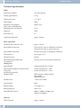
Technical specifications . . . . . . . . . . . . . . . . . . . . . . . . . . . . . . . . . . . . . . . 66
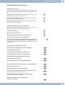
Brief description of functions . . . . . . . . . . . . . . . . . . . . . . . . . . . . . . . . . . . . 69
Quick Reference for Voicebox . . . . . . . . . . . . . . . . . . . . . . . . . . . . . . . . . . . . 73
Index . . . . . . . . . . . . . . . . . . . . . . . . . . . . . . . . . . . . . . . . . . . . . . . . . . . 75
III
Table of contents
IV
Important notes for using the PABX system
Description
Description
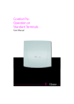
The PABX is an ISDN telecommunications system (PABX) for interfacing with the Euro ISDN (DSSI) protocol). The
PABX system is equipped with an external ISDN port that is configured for connecting to the ISDN access point of the
network service provider. You can set the ISDN port either as an internal or external ISDN port. You can program the
type of connection for the external ISDN connection either as a multipoint connection or as a point-to-point connection (default setting). Depending on the type of PABX, up to eight (8) analog terminals can be connected (base model). You can use door intercom units as modules in the PABX system, or as additional devices at the internal analog
port. Module slots for ISDN and a/b ports, contacts modules, 4 DSP modules and up to 4 analog access lines (POTS)
are also provided. User-specific answering machines (voiceboxes) can be used after installing the optional Compact-Flash Card. Internal numbers (the destination for the extension number with point-to-point connection) between 0... 99 can be freely assigned. The features provided for analog terminals can only be used with terminals which
use tone dialing and which are equipped with a flash button. Flash duration detection can be set by PC configuration.
Analog terminal devices that use pulse dialing can not be used for functions or codes. Please note that the buttons on
some ISDN terminals available on the market may limit the use of the features provided by the PABX system.
All terminal devices connected to the system must be »TC Terminals Guideline« or »R&TTE Guideline« approved.
The PABX system also provides all of the functions necessary for high-speed Internet access for a single pcs, or for
complete LANs via xDSL or ISDN. Here the firewall integrated into the PABX system, together with the NAT (network address translation) function, provides the necessary security; the functions DHCP server and DNS proxy ensure that the scope of configuration, both for your PABX system and your PC, is kept to a minimum.
Internet access for all of the PCs connected to the PABX system is provided via one single connection (SUA - single
user account); only one set of access data is required from your Internet service providers (ISP).
The CD supplied with this system contains other important documentation:
Assembly instructions
System telephones
Description of functions
Operating instructions for Voicebox
Note
For a description of the features please refer to the online help for the »Professional Configurator« or the user information on the CD.
Note
The first time you start the Configurator you will be asked to enter your user ID and password. Use »Service«
as your user ID and also »Service« as the password. Please note that these words are case-sensitive! Once
you’ve been logged on to the Configurator you can change your user ID and password as you like.
Safety notes
Important notes for using the PABX system
· Unauthorized opening of the PABX and improper repairs may result in risk of injury for the user.
· Unplug the 230 V AC connector plug before removing the enclosure cover and working on the cable terminal bay. Replace the cover before reconnecting the 230 V AC connector.
· Do not expose the inside of the PABX to any liquids; this would pose a risk of electrical shock. If
you expose the inside of the PABX to liquids the PABX can be destroyed.
· You should not connect or disconnect any lines during thunderstorms.
1
Symbols
Cleaning
· Only terminals with SELV and/or which comply with ETS 300047 may be connected to the PABX
system. This regulation is fulfilled when approved terminal devices are used as intended.
· Find an appropriate installation location. The distance from the network termination (ISDN connection) of your service provider and the 230 V AC outlet should not exceed 1. 5 meters.
· Water or heating pipes near the installation location can be used to install functional grounding.
Ensure that these lines are connected to the grounding circuit connector of your house service
connection.
· The PABX is powered by a 230 V AC utility outlet. Please ensure that the electrical outlet (groun-
ding outlet) for the PABX (and for additional devices where required) is installed such that it is
freely accessible at all times and that it is installed by a qualified electrician to prevent any risks of
personal or material injury/damage! Where at all possible, provide a separate power circuit for
the 230 V AC connection of your PABX system. This protects your PABX from short-circuits that
may occur in other in-house equipment.
· We recommend installing an overload protection to protect your PABX against surge that can so-
metimes occur during thunderstorms. For further information please contact your local electrician.
· To prevent mutual interference, do not install your PABX system in the immediate vicinity of
electronic devices such as stereo equipment, electronic office equipment or microwave units.
Avoid installing your PABX near sources of excessive heat, e.g. radiators or in rooms with excessive humidity.
The ambient temperature must not exceed 40° C.
Cleaning
Please observe the following points: You can clean your PABX without any difficulties. Use a slightly moistened cloth
or an anti-static cloth for this. Do not use any solvents! Never use a dry cloth; Electrostatic charges could damage the
electronics in the system. Always ensure, however, that no moisture penetrates into your PABX, as this could result
in damage to the PABX.
Loss of power
On loss of power (230 V AC power supply) the PABX is not operational, meaning that you can make neither internal
nor external calls. An ISDN terminal device with emergency power capabilities can continue to be operated however.
On return of power, functions which have been configured by the user, e. g. internal and external connections, are not
active. The features configured using setup programmeming are unaffected by a loss of power.
Symbols
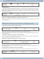
Please note: Different terminal devices will not necessarily have the same dial tones, ringing signals or procedures for
use.
For further information on clock frequency and length, please refer to the assembly instructions.
Symbols used
b
g
a
l
t
1x0
*#
2
Lift up the handset of your telephone.
This symbol indicates the call status. You have lifted the handset of your telephone.
Replace the handset of your phone in the carriage, or the telephone is idle.
Indicates signaling at a terminal device, for example your phone rings.
You can dial the desired number.
One of these symbols indicates that you should dial the digit shown, or a certain character.
Loss of power
Symbols
=x)
~
These symbols indicate a selection of digits or characters from which you can choose the appropriate
one.
X
R
q
d
#
This symbol prompts you to select a certain digit or character from a list or table.
Prompts you to press the flash key (signal key).
Indicates that an acknowledgement signal can be heard in the handset.
Indicates a conference call.
WhenyouenterthenumberfordialingviaanSIPprovider,dialingisnotperformeduntilaround5secondsafter the last digit has been entered. Dialing is performed immediately when you pressthe # key
after entering the number. In this case, the terminal device must also be capable of dialing into the
phone system with the #.
Supported Features
The following ISDN features are supported by the PABX system at the exchange of the network service provider;
some of these may have to be applied for at your service provider.
· CD: Call deflection (forwarding of calls)
· PR: Partial Rerouting. Individual call forwarding for terminal devices at a point-to-point connection
· CLIP / CLIR: Activation/Deactivation of caller ID to party being called.
· COLP / COLR: Activation/Deactivation of called party ID to caller.
· AOCD: Transmission of charge costs during a call.
· AOCE: Transmission of costs of call at end of call.
· AOCS: Transfer of tariff information during the calling phase, for example for pay phones.
· CCBS: Completion of call to busy subscriber, as soon as subscriber is available.
· CCNR: Call-back to available subscriber as soon as that party has lifted and replaced the handset.
· MCID: Malicious caller ID (tracing).
· CFB / CFU / CFNR: Call forwarding.
· UUS1: Transmission of user-defined text messages.
· SUB: Extended addressing for a terminal device.
· X.31: Support for packet data (V-25) on the D-channel, for example for electronic cashiers.
· SMS in the fixed-line network.
Note
Please note that some of the features described in these operating manual must be applied for at your service provider.
3
Symbols
Loss of power
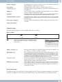
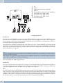
Display / LEDs
Note
You can de-activate all of the LEDs except for »Power / On« and »LAN« in the configuration of the PABX system.
Power /
Operation
ISDN /
POTS
DSL
LAN
USB
Ready for operation indicator.
Green lit:
When the PABX is ready for operation.
Green flashing:
When 480 data records have been saved in the charges memory of the PABX
Indicates the allocation of each B channel for the external ISDN connection.
Green lit:
ISDN port ready for operation or POTS-module plugged in
Green flashing:
One B channel busy, or an existing connection via the POTS module
Green flickering:
Two B-channels busy
Indicates the function of the DSL router:
Green lit:
DSL connection established
Green flashing:
Data link established
Indicates the network connection status:
Green lit:
100Mbit/s network connection established
Green flickering:
100Mbit/s data link
Orange lit:
10Mbit/s network connection established
Orange flickering:
10Mbit/s data link
Red flickering:
Network link collision
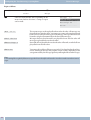
Indicates the status / activities on the USB port.
Not lit:
Green lit:
Green flickering:
CF-Card
4
The USB port of the PABX system is not ready for operation at the connected
PC (not logged in, or not recognized), or when the PC/USB port is in the suspended mode.
The USB port of the PABX system is ready for operation at the connected PC
(USB driver active). PC applications that run via the USB connection can be
started.
Dataisbeingexchangedviathe USBport. For ex.: CAPIapplication programs,
CTI applications or new software download into PABX system.
Indicates that a Compact-Flash Card has been plugged in:
Green lit:
CF-Card plugged in
Green flickering:
Data being transferred to the CF-Card
Loss of power
Symbols
Note
Refer to »Voicebox operating instructions« on the CD for further information about using the Voicebox.
Voicebox«.
All LEDs lit
New firmware not properly identified by the PABX. Please repeat the operation.
All LEDs flashing
New firmware being downloaded into the PABX. Do not remove the plug-in power supply unit for the PABX system
during this phase, as it can result in data being lost in the PABX.
5
Features
Features
Examples of the features and functions supported / offered by your PABX system are listed below. Detailed information and description of functions can be found on the CD-ROM.
· Transfer of calls to a specific team or extension
· Analog exchange line ports (POTS)
· Changeable access codes
· Call waiting
· Answering machine (analog or ISDN device) connectable
· Call modes (day/night call modes)
· Call forwarding (Call rerouting) continuous, on busy or on no answer
· Remote programming of call forwarding
· Reading and deleting a call forwarding (internal / external)
· Call deflection during an ongoing call (CD – Call Deflection)
· Announcement device
· Voice announcement before answering
· Connections for terminal devices (analog, ISDN), PC and Modules
· Programming direct exchange line access separately for each extension
· Automatic completion of call to busy subscriber or on no answer
· User to User Signaling 1 UUS1
· Block dialing (for analog terminal devices only)
· Trunk group seizure for external ISDN connections
· Trunk group seizure programmable for each internal subscriber
· Reserving a trunk group (ISDN connection)
· CCNR per subscriber
· Data records for coupled calls
· Setting the date and the time
· Accepting date and time from the exchange
· Dialer protection (Unrestricted data)
· Direct dial-in
· Three-party conference call
· Enable messaging function and message reception separately for each internal extension
· Programming terminal devices for analog connections
· Extended call allocation with point-to-point access
6
Features
· External line access digit for caller list
· Remote control for remote call forwarding, room monitor, door opener and switching contacts
· Remote access protected by PIN2 (6-place) of the PABX
· Malicious caller ID (tracing / MCID – Malicious Call Identification)
· Follow me
· Gateway external for ISDN, internal for analog connection
· Meter pulse for analog connections (12 kHz or 16 kHz)
· Transferring calls with or without prior notice (switching)
· Storing communication costs and call data records
· Communication cost display and charge counter of internal terminal devices
· Call cost account (cost limit, allowance account)
· Call pick-up (Pick up)
· Picking up calls from an answering machine
· Picking up calls for a specific subscriber
· Keeping ISDN layer 2 permanently active for each external ISDN connection
· Calendar (2 calendars with 4 switching times per week day and holiday)
· Changing code numbers for specific features
· Keypad functions (net direct)
· Support for multifunctional devices at the analog ports
· PABX-configuration over ISDN or USB, LAN-port
· Configuration of system features using a telephone
· Programming access to the PABX protected by PIN 1 (4-place)
· Cost conversion factor
· Country-specific parameters can be set
· Least Cost Routing (LCR) including support of gateways
· Broker`s call
· Signaling features
· PABX extension modules
· Assignment of names in the PABX system for subscribers, teams and connections
· Loss of power: Emergency operation possible
· Emergency call numbers in the PABX (6 numbers)
· Programming of emergency telephones
· Data packet transfer (X. 31)
7
Features
· Parking (TP - Terminal Portability) at the internal ISDN port
· PC-connections (USB, LAN) for configuration
· PIN (password) required for accessing the PABX
· Project numbers / client numbers
· Room monitoring from internal and external terminals
· Routing discrimination
· Router inhibition
· Inquiry call
· System-parked inquiry call
· Number identification (NI) possible for internal subscribers
· Assigning telephone numbers for external calls separately for each internal subscriber
· Defining your own number for the next call
· Disable calling line identification (setting in the exchange)
· Disable calling line identification (subscriber-specific setting in the PABX)
· Temporarily suppressing transmission of your own number
· Variable AC ringing voltage for analog connections (25 Hz or 50 Hz)
· Station guarding (do not disturb)
· Call signaling (group ringing: simultaneous, linear, rotating, adding, linar / rotating or simultaneous on no response).
· Switching contacts available on the doorphone module and the switching contact module
· Internal or external activation of switching contacts
· Protection of data link
· Service access (remote configuration, remote maintenance, software downloads)
· SIP-telephony over DSP-module
· SMS (short messages), enable SMS reception separately for each internal subscriber
· Automatic setting of winter and summer time
· Sub-addressing
· System menu for the PABX
· System telephones
· Configuring system telephones through the PABX
· Call modes for teams
· Telephone directory / speed dialing from the telephone directory
· Telephone interlock
8
Features
· Appointment call / morning call
· PABX can be used at point-to-point or point-to-multipoint access (also mixed)
· Door intercom device (door terminal module) connectable via door intercom module
· Door intercom adapter connectable
· Switching calls to a busy subscriber
· Switching functions
· Voice applications for music on hold, morning call announcements or Voice announcement before answering
· Call authorization (access to the public telecommunications network)
· Switching call authorizations (for external calls) automatically
· Dialing control (barred numbers: 10 numbers / Unrestricted numbers: 60 numbers)
· Calling method configurable for analog terminal devices (DTMF with flash or pulse dialing)
· Music on Hold, internal or voice applications
· Intercom, intercom call reception separately configurable for each internal subscriber
· Central / second bell
9
Operation
Making phone calls
Operation
Note
For a description of the features please refer to the Description of functions on the CD.
Not all of the features described here may be implemented in the standard ISDN connection supplied by your network service provider. Contact your service provider to determine which features come standard with your ISDN access and which ones you must apply for separately.
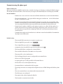
If your phone is set for »Automatic line access« you must first press the * key when you lift the handset b before beginning any internal call procedures. The symbol b is highlighted in color, as shown in the example below, for the
corresponding performance feature.
b
t
g
Lift up handset
Making internal calls
Conduct your call
Making phone calls
Some terminal devices use their own special procedures for the functions described in the following. Refer to the operating instructions for the terminal device being used for detailed information.
Only telephone connections, i. e. calls between subscribers, are presented in the following usage procedures as examples. For analog telephones, these functions are only described for tone dialing terminal devices equipped with a
flash key. The tones and signals described below are heard when using analog telephones. These tones may be different for ISDN telephones and analog telephones which generate their own dial tones. Other information may also be
shown in the display of these telephones.
Note
Please note: ISDN terminal devices connected to the ISDN connection may not have the same signals, ringing cycles
or operating procedures as the internal terminal devices for the PABX system.
Making outside calls
Making external calls without direct exchange line access
b
0
t
g
a
Lift up handset
Dial line access digit
Dial external number
Conduct your call
Terminate your call
Note
If you hear the busy signal after dialing the first 0 your telephone either does not have authorization for making external calls, or the external ISDN connection is busy.
Making outside calls with direct exchange line access
10
b
t
g
a
Lift up handset
Dial external number
Conduct your call
Terminate your call
Specific trunk group seizure
Operation
Specific trunk group seizure
b
*8
Lift up handset
Select trunk group
ISDN, POTS(0...4)
*8#
t
g
Select trunk group
ISDN, POTS, SIP-Prov. (00...04), (10...19)
Dial external
number
Conversation
or
a
Making internal calls
All phone calls, fax transmissions or data transmissions that take place between internal analog and ISDN terminal
devices are internal connections for which no charges are billed.
Making internal calls without »Direct exchange line access«
b
t
g
a
Lift up handset
Dial internal extension number
Conversation
Terminate your call
Making internal calls with »Direct exchange line access«
b
*
Lift up handset
t
g
a
Dial internal extension
number
Conversation
Terminate your call
Accepting calls
l
b
g
a
Telephone rings
Lift up handset
Conversation
Terminate your call
Accepting calls (Pick-up)
Picking up calls from within the group
Note
Picking up a call is possible only within the pick-up group to which your terminal device has been assigned via configuration.
A telephone near you begins ringing. You would like to accept the call at your own phone.
b
*0
g
Lift up handset
Accept call
Conversation
Picking up calls from the answering machine
b
Lift up handset
*0 /
#0
Take call / conversation
from the answering machine
g
Conversation
Picking up calls for a specific subscriber
Picking up of calls for a specific subscriber applies to the entire pabx system and is not bound to groups.
11
Operation
Automatic completion of call to busy subscriber or on no answer
b
*1
t
#
Lift up handset
Dial this code
Select internal subscriber
g
You can conduct the call from your own telephone
Telephone interlock
Use this feature to download configured characteristics for outgoing calls into another phone. This includes trunk
group seizure, authorizations etc. All charges will be billed to your own phone. If possible, the called party sees the
numer or name in the display of his or her phone. This applies also to an inquiry call. During configuration, a PIN is
allocated to each subscriber.
b
*5*
t
t
g
Lift up handset
Dial this code
Enter PIN
(subscriber-specific)
Select external
party
Conduct your call
Automatic completion of call to busy subscriber or on no answer
This function can only be used by telephones that permit suffix dialing. Automatic call completions from an inquiry
call are not possible.
Note
External Completions of call to busy subscriber are deleted after a period defined by the exchange.
Programming »Completion of call« for analog telephones
g
*40
Internal or external subscriber is
busy or does not answer
q
a
Ack.
signal
Replace
handset
When the subscriber that was called hangs up his/her handset your telephone will ring.
When you lift up your handset the subscriber for which completion of call is active is called. If the party answers you
can conduct your call.
Programming »Completion of call on busy« for ISDN telephones
This feature is supported for ISDN telephones by the PABX at the internal ISDN connection. Please refer to the operating instructions for your ISDN telephone for proper use.
Programming »Completion of call on no answer« for ISDN telephones
g
*40
Internal or external subscriber does not answer
q
a
Ack. signal, voice announcement
or information on display
Replace
handset
When the subscriber that was called hangs up his/her handset your telephone will ring.
When you lift up your handset the subscriber for which completion of call is active is called. If the party answers you
can conduct your call.
Canceling automatic completion of call for analog telephones
Analog telephones use this procedure for canceling internal completions of call to busy subscriber and no answer.
12
b
#40
q
a
Lift up handset
Cancel completion of calls
Ack. signal
Replace handset
Defining your own number for the next call
Operation
Deleting an automatic »Completion of Call on No Answer« with ISDN phones
Internal completion of calls on no reply is canceled with ISDN telephones using the following procedure.
b
#40
q
a
Lift up handset
Cancel completion of calls
Ack. signal
Replace handset
Defining your own number for the next call
b
#8
t
t
t
Lift up handset
Code number
Select external ISDN connection (1...2)
Index
(0 … 9)
Dial call
number
Temporarily suppressing transmission of your own number
Note
This feature must be applied for at your network service provider.
Transmission of the caller’s own number is suppressed using the following procedure with analog terminal devices.
Please refer to the operating instructions for ISDN terminal devices on how to initiate this feature.
b
*594
t
Lift up handset
Dial this code
Dial call number
Trunk group reservation
Neither for IP-phones nor trunk groups with SIP-providers.
Activating trunk group reservation
g
*40
You hear the
busy signal
q
a
l
b
Ack.
signal
Replace
handset
The selected ISDN
connection becomes
available
Lift up
handset
Deleting trunk group reservation
b
#41
Lift up handset
q
a
Ack. signal
Replace handset
Speed dialing from the telephone directory
b
*#
Lift up handset
t
l
g
Select speed dialing index (000 … 499)
Subscriber is called
Conversation
Voice announcement
Note
A voice announcement extension can be reached by internal extensions only.
13
Operation
Announcement
b
t
g
a
Lift up handset
Internal number for the voice announcement extension
Voice announcement
Terminate voice announcement
Announcement
Refer to the operating instructions for your telephones whether the phones support the message feature.
Making an announcement
b
*540
Lift up handset
t
q
g
Internal number or team
number
Ack. signal
Announcement
Enabling / inhibiting announcements
You can enable or inhibit the sending of messages to your telephone. If you have disabled messages being sent to your
phone, the caller that is attempting to send a message to you will hear the busy signal.
b
*/#
591
Lift up handset
Enable announcements /
Inhibit announcements
q
a
Ack.
signal
Replace
handset
Room monitoring
This feature can not be used in conjunction with inquiry call, call forwarding or team call functions.
Note
Room monitoring is deactivated after each pabx configuration and must subsequently be enabled and configured
once again.
Enabling room monitoring for an internal telephone
b
*593
Lift up handset
q
Ack.signal
Do not replace handset /Do not deactivate
hands-free calling
Room monitoring from an internal telephone
b
t
q
Lift up handset
Dial the number of the telephone to be used for room monitoring
Ack.
signal
Room monitoring is activated
Room monitoring from external telephones
You are located at an external telephone.
Lift up the handset of the phone from which you wish to conduct room monitoring and dial the external number to
which the service number for the PABX is assigned.
If remote access has been enabled and is possible at this time you will hear the special dial tone of your PABX.
Set your phone to frequency (DTMF) dialing, or use a DTMF manual transmitter.
14
Malicious call identification (Tracing)
Operation
t
q
t
q
Enter PIN 2
Ack.
signal
Dial the number of the telephone to be used for room
monitoring
Ack.
signal
Room monitoring is activated
To end room monitoring, hang up the handset of the external telephone.
Malicious call identification (Tracing)
g
*51
Ongoing call, or caller
hangs up
q
a
Ack.
signal
Replace
handset
Note
Attention: Only hang up the handset after you have entered the code for tracing the caller and hear the positive acknowledgement signal.
Allocating Project Numbers
Assigning a project number for a call you initiate
b
*50
Lift up handset
t
#
Enter project number ( max. 6-place)
q
t
Ack. signal
Dial call number
Project number for incoming external call to ISDN terminal device
You can use this feature at an ISDN terminal if your ISDN terminal device supports the function »Network Direct«
(keypad).
You are conducting a call and wish to register it for a project.
g
*50
Conversation
t
#
Entering a project number
(max. 6 - place)
q
g
Ack.
signal
Continue call
Project number for an external call
You can use this feature at an analog or an ISDN terminal device if your ISDN terminal does not support the function
»Net direct« (Keypad) during an ongoing call.
You are conducting a call and wish to register it for a project.
g
Conversation
R
*50
t
Entering a project
number
(max. 6 - place)
#
q
Ack.
signal
R
g
Continue call
15
Operation
(keypad-function »Net fixed«)
(keypad-function »Net fixed«)
b
0
* or #
t
a
Lift up handset
Dial line access digit
Initiate keypad function
Enter codes
Replace handset
Sending a fax from a multi-function terminal
b
*773
t
l
Lift up handset
Enter code number for fax group 3
Dial the external number
Direct dial-in
Making telephone calls with activated direct dial-in
b
t
Lift up handset
Begin dialing within the configured time
Entering and activating a direct call number
b
*65
Lift up handset
t
#
MSN extension number (without line access digit)
q
a
Ack. signal
Replace handset
Note
Now, when you lift up your handset the direct call number will be dialed after the specified time (default setting: 5
seconds).
Activate/deactivate direct dial-in
b
#65*
Lift up handset
Deactivate
direct dial-in
or
*65#
q
a
Reactivating a direct
dial-in
Ack.
signal
Replace
handset
The numbers stored in the PABX for direct calls are retained even when the direct call function is deactivated.
Deleting a direct dial-in number (phone number)
b
#65#
q
a
Lift up handset
Delete a direct dial-in
Ack. signal
Replace handset
The stored direct dial-in number is deleted.
Room inquiriy
You can call another party at any time during an ongoing call.
g
You are conducting a call.
You would like to call another party.
R
16
Press the R key.
You will hear the internal dial tone.
Call waiting
Operation
If you wish to speak to an external party, dial 0 first.
t
If you hear a busy signal after dialing 0, either your telephone does not have proper authorization for
an external call, or the line is busy.
Dial the number of the party you wish to call.
You will hear the ringing signal in your handset.
t
The party will be called.
The party being called lifts up the handset of his/her phone.
Conduct your call.
g
To end the inquiry call press the Disconnect key on your ISDN phone.
or
With analog telephones:
R0
R1
g
The connection put on hold is terminated. The active connection remains.
The active connection is terminated and you return to the call that was previously put on hold.
Continue with your call.
Initiating a system parked inquiry
g
Youareconductinganexternalcall.Youwanttomakethiscallavailableforasystem-parkedinquiry.
R
t
q
Press the R key. You will hear the internal dial tone.
a
Replace the handset, the external call is put on hold in the waiting loop.
Dial any one of the 4 configured internal system parked inquiry numbers or the fixed code *596. You
will hear the positive acknowledgement signal.
If you hear the busy tone, dial the next configured internal extension number
Accepting a system-parked inquiry
b
You wish to accept the call from a system-parked inquiry.
Dial any one of the 4 configured internal system parked inquiry numbers or the fixed code *596.
t
g
You have accepted the call.
Call waiting
During an ongoing call you can accept, or refuse, a waiting call at any time.
Enable / Inhibit Call Waiting for a Further Call
b
* /#
Lift up handset
enable / inhibit
58
q
a
Ack. signal
Replace handset
Accepting a waiting call (room inquiry with waiting caller)
g
You are conducting a call.
A second party calls you.
You hear the call waiting signal.
R2
g
Dial this code.
Youwillbeconnectedwiththewaitingparty.Yourfirstcallisputonhold(see»Inquirycall«).Forfurther procedures refer also to »Broker’s call« or »Three-party conference call«.
Accepting a waiting call
g
You are conducting a call. You hear the call waiting signal.
a
l
Replace handset (your first call is terminated).
Your phone rings.
17
Operation
b
Transferring calls with and without advance notice
Lift up the handset of your phone. You will be connected with the waiting party.
Refusing a waiting call
g
You are conducting a call.
A second party calls you.
You hear the call waiting signal.
R0
Dial the code for refusing the waiting call. The caller can be switched to the waiting queue, or the call is
established and the caller will hear the busy signal.
Transferring calls with and without advance notice
Transferring calls internally without advance notice
You can transfer calls when you dial the number of the internal party and then hang up the handset. The internal party is then called and can take the call when he/she lifts the handset.
g
You are conducting an external call.
R
Press the R key.
You will hear the internal dial tone.
t
Dial the number of the internal party to whom you wish to transfer the call.
You will hear the ringing signal in your handset.
The party will be called.
If you hear the busy signal press the R key again to retrieve the call that is on hold.
a
Replace the handset. The party will be called. The party being called lifts up the handset and conducts
the external call. If the called party does not lift up his/her handset you will be called back at your telephone after a time interval set during programming.
Transferring calls with advance notice
You wish to transfer an internal or external call to another internal party and speak with that party beforehand.
g
You are conducting an internal or external call. You wish to transfer the call to another party.
R
Press the R key. You will hear the internal dial tone.
If you hear the busy signal, press the R key again to retrieve the call.
t
Dial the number of the party you wish to call.
You will hear the ringing signal in your handset.
The party will be called.
The party being called lifts up the handset of his/her phone.
g
Conduct this internal call.
Tell your internal partner that you wish to transfer the call currently on hold to him/her.
a
Replace the handset.
The other internal party can then continue with the call.
(Explicit call transfer)
Connecting
Please note that ISDN terminal devices can only utilize the feature »Connect« via a special key or menu function. The
following procedure applies only to analog telephones.
g
You are conducting a call with party 1.
A further call is signaled, for example by call waiting.
18
Broker’s call
Operation
R2
Dial this code.
Party 2 answers; you can speak with Party 2 Party 1 is put on hold.
R4
You would like to connect the two parties with one another.
Dial this code.
Thetwopartiesarethenconnected.Thechargesfortheconnectionarebilledtothepartywhoestablished the connection.
Broker’s call
g
Youareconductingacallandwish to speakto afurther party, without the first caller being able to hear
your conversation with the second caller.
R
Press the R key.
You will hear the internal dial tone.
t
If you wish to speak to an external party, dial 0 first.
Dial the number of the party you wish to call.
You will hear the ringing signal in your handset.
The party will be called.
The party being called lifts up the handset of his/her phone.
g
You are conducting the call.
The first call is put on hold.
R2
Dialthiscodetoreturntoyourfirstcaller;thesecondpartyisputonhold.Youcanthenusethiscodeto
switch back and forth between the two callers.
or
R0
You can end the call that is on hold.
Dial this code.
or
R1
You can end the current call.
Dial this code.
If you switch back and forth between an internal caller and an external party (broker’s call) and then hang up your
handset, your call is terminated and the two callers will be connected with one another!
If you switch back and forth between two external parties (broker’s call) and then hang up your handset, the current
call is terminated and the caller on hold will call you by way of the »Recall«.
If, during a broker’s call, you press the R key and then dial 4, the two external parties are connected with one another
and your call with both of the external parties is terminated. The charges for the call that you initiated will be billed to
you.
Three-party conference
g
R
You are conducting a call with one party and wish to include a further party in the call.
Press the R key.
You will hear the internal dial tone.
If you wish to speak to an external party, dial 0 first.
t
Dial the number of the party you wish to call.
You will hear the ringing signal in your handset. The party will be called.
The party being called lifts up the handset of his/her phone.
g
R3
You would like to include this party in the first call.
Dial this code.
19
Operation
Call forwarding
d
d
Conduct your three-party conference call.
R2
g
Dial this code.
You would now like to exclude the party that you first brought into the conference call from further
conversation. This caller then remains on hold in an inquiry call.
You can then continue your call with the second party. The first party is on hold.
The conference is ended when you hang up your handset. A party included in the conference call can hang up at any
time and the party which initiated the call can then continue the conference with the remaining callers.
Call forwarding
Note
The PABX recognizes automatically by the length of the number whether call forwarding is to be made to an internal or external subscriber. This is why the destination number for call forwarding to an external subscriber is always
input without the line access digit (LAD).
Activating call forwarding
b
*
Lift up handset
61 / 62 / 63
t
#
Permanent call forwarding / Destination number for call
Call forwarding on no reply /
forwarding
Call forwarding on busy
(without line access digit)
q
a
Ack.
signal
Replace
handset
Deactivating call forwarding
b
#
Lift up handset
61 / 62 / 63
q
a
Permanent call forwarding /
Call forwarding on no reply /
Call forwarding on busy
Ack.
signal
Replace
handset
Silent signalling
Deactivating call signaling for analog terminal devices
b
*57
Lift up handset
0/1/2
q
a
internal + external calls /
only external calls /
only internal calls
Ack.
signal
Replace
handset
Activating call signaling for analog terminal devices
b
#570
Lift up handset
q
a
Ack. signal
Replace handset
Call modes (Day- / Night)
Activating team call assignment for one team
20
b
*/#
Lift up handset
Day / Night call mode
93
t
q
a
Enter team number (00...19)
Ack.signal
Replace handset
Teams
Operation
Switching team call assignment for all teams
b
*/#
93*
Lift up handset
Day / Night call mode
q
a
Ack. signal
Replace handset
door terminal (door intercom device) Switching call modes for a doorbell button
b
*/#
Lift up handset
Day / Night call mode
96
1
t
q
a
select door terminal
Select bell button
(1...4)
Ack.
signal
Replace
handset
door terminal (door intercom device) Switching call modes for all door terminal modules
b
*/#
96*
Lift up handset
Day / Night call mode
q
a
Ack. signal
Replace handset
q
a
Ack. signal
Replace handset
Switching all call modes (all teams and door terminal modules).
b
*/#
9*
Lift up handset
Day / Night call mode
Teams
Enabling / Inhibiting a subscriber of a team (log-in, log-off)
Proceed as follows in order to enable or inhibit your phone for a team
b
*/#
Lift up handset
Subscriber
enable/inhibit
943
t
q
a
Team number
(00 ... 19)
Ack.
signal
Replace
handset
Enabling / inhibiting a subscriber for all teams (log-in, log-off)
Proceed as follows in order to enable or inhibit your phone for all teams.
b
*/#
943*
Lift up handset
Enable/Inhibit subscribers
q
a
Ack. signal
Replace handset
Activating the switching function for an internal subscriber
b
*/#
91
q
a
Lift up handset
Activate day mode / night
mode
Code
Ack. signal
Replace handset
Follow me
Setting up or deleting an internal Follow me
b
*/#
64
t
Lift up handset
Set up / delete
Follow me
*1)
#
q
a
Ack. signal
Replace handset
21
Operation
Block dialing (Austria)
*1) Internal number whose calls are to be forwarded.
Call will then be forwarded to the specified telephone.
Setting up /deleting call forwarding from an external location
Lift up the handset of your phone and dial the external number to which the service number of the PABX system has
been assigned.
If remote activation of call forwarding has been enabled you will hear the special dial tone for your PABX system. Set
your phone to DTMF dialing:
t
q
*
Enter PIN 2
Ack. signal
Set up
64
t
q
#
Enter PIN 2
Ack. signal
Delete
t
*
t
*1)
Set up
*2)
64
t
#
q
Ack. signal
#
*1)
q
Ack. signal
*1) Internal number whose calls are to be forwarded.
*2) Destination number for call forwarding (outside number without LAD).
You will then hear the positive acknowledgement signal for about 1 second; the connection is then terminated and
you will hear the busy signal.
Replace the handset.
Block dialing (Austria)
b
*55
Lift up handset
0
t
#
Line access digit
Call number
*1)
g
*1) Begin dialing by pressing the # key. Only now is the call transferred to the exchange.
Call Through
This action may only be performed from an external phone.
b
t
Lift up handset
Select "Numbers in
my phone system for
call-through
q
t
t
1) Enter PIN
Dialing external destination numbers
g
1) The configuration of the PABX system is decisive for this input (with or without PIN, with number recognition, or
both).
22
Wake-up call
Operation
Least Cost Routing (LCR)
Please note that there are some providers whose services must be applied for. Some of these providers automatically
set up a connection to enroll unregistered customers. If you terminate such a connection during dialing and then
subsequently attempt to set up this link again, this may result in errors during calling (communication will not be
established). In this case it will be necessary to deactivate the provider concerned in the LCR professional on the
WIN-Tools CD and to update the date records in the PABX.
You can activate/de-activate the LCR procedure using either the »Professional Configurator«, or a code sequence on
the telephone.
Activating the LCR procedure
b
X
**
Lift up handset
q
====
q
7812
q
Ack.
signal
Enter PIN
(0000 = default setting)
Ack. signal
Code
Ack.
signal
q
====
q
781#
q
Ack.
signal
Enter PIN
(0000 = default setting)
Ack. signal
Code
Ack.
signal
Deactivating the LCR procedure
b
X
**
Lift up handset
Wake-up call
Configuring wake-up calls from the room phone (one-time morning call)
b
*72
Lift up handset
=&
§=
Hours
Minute
q
a
Ack. signal
Replace handset
Enter the hour desired for the morning call between 00 and 23 (in this example 6 am).
=&
§=
Enter the minute for the morning call between 00 and 59 (in this example 6.30 am)
Canceling a wake-up call
b
#72
Lift up handset
q
a
Ack. signal
Replace handset
Configuring a wake-up call from the »Reception desk phone«
In addition to configuring wake-up calls using the room phone, wake-up calls can also be defined for several days in
advance from the »Reception desk phone« (system feature).
Answering a morning call
l
b
g
The telephone in your
room rings
Lift up handset
a
Music on Hold or voice announce- Now hang up the handset and the
ment
wake-up call is ended
Door intercom device
Making a door interphone call / Opening the door
l
b
g
Door intercom
call
Lift up handset
Conversation via door
intercom
R
*99
x
Code
23
Operation
Signaling features
x
1
q
a
Door opener
Ack.
signal
Replace
handset
Activating the door opener
b
*99
1
q
a
Lift up handset
Code
Door opener
Ack.signal
Replace handset
Note:
If a door entry phone call is signaled at a different telephone or if you hear the door bell ring, you can dial the door intercom phone number and pick up the door entry phone call yourself, provided you have the corresponding rights
to do so.
Opening the door with ISDN telephones that do not support suffix dialing:
If you wish to open the door, terminate the door entry phone call and replace
Lift up the handset again and dial *991 to open the door.
Actuating the door terminal externally
b
Lift up handset
t
q
Service num- Special dial tober
ne
t
q
*991
q
a
PIN 2
Ack. signal
Door opener
Ack. signal
Replace handset
Signaling features
Activating/ de-activating alarm call feature
b
*95
Lift up handset
t
t
q
a
Alarm call list
01 ... 06
function
0...2
Ack.
signal
Replace
handset
Alarm call list
The terminal device must have been entered into the list during configuration:
01x06 Alarm call list 01...06.
Function:
0
1
2
Deactivating the alarm call feature.
Activating the internal alarm call feature.
Activate external call feature.
Switching contacts
Note
In the event of a loss of power and after a reset the switching contacts are idle.
24
Switching contacts
Operation
Activating/ de-activating switching contacts
b
*/#
Lift up handset
Activate/ deactivate
970
t
q
a
Switching contact01...03
Ack. signal
Replacehandset
Switching contact with button function
b
*971
Lift up handset
t
q
a
Switching contact 01...03
Ack. signal
Replace handset
The switching contact closes for the time interval you have programmed (1 ... 999 seconds).
Switching contact with a switch function (remote)
b
t
q
t
q
Lift up handset
Service number
Special dial tone
PIN 2
Ack. signal
x
*/#
970
Activate/ deactivate
x
t
q
a
Switching contact 01...03
Ack. signal
Replace handset
Switching contact with a button function (remote)
b
t
q
t
q
Lift up handset
Service number
Special dial tone
PIN 2
Ack. signal
x
*971
x
t
q
a
Switching contact 01...03
Ack. signal
Replace handset
The switching contact closes for the time interval you have programmed (1 ... 999 seconds).
Terminating an Internet connection from the phone
Using a corresponding operating procedure you can terminate an ongoing Internet connection from any phone.
b
#66#
q
a
Lift up handset
Disconnect Internet connection
Ack. signal
Replace handset
25
Communication / Call charges
Modified code numbers
Modified code numbers
You can program your PABX with individual code numbers for the following features. Customizing the default
PABX numeric code adds an extension from the internal telephone number plan of the system.
Enter all changed code numbers in the table. Various code numbers can be entered for the »System-parked inquiry«
feature.
Feature
Line access digit
System parked inquiry (four codes)
Default code number
Changed code number
0(UK9)
*596
The operation principle of the features whose code number has been changed remains as described. You can either
use the changed code number (internal extension number) or the code number given in the operating instructions
(except for the line access digit).
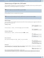
Communication / Call charges
The PABX generates a call data record for every external call. The call data records contain detailed information
about the call.
For ex.: Date and time, duration of the call, number of the called party, number of the calling party, type of connection, communication costs and possible project numbers.
Incoming calls can be logged in two different ways.
· Only incoming calls with a certain project numer are stored.
· All incoming calls are stored.
Output of call data records
You have two options to output the stored call data records. For example:
· Internal ISDN connection
· USB/LAN-connection
Communication cost display
The communication / call charges can be displayed at any terminal devices that support this feature. ISDN and analog terminal devices use different methods for transmitting and displaying communication costs.
Charge counter
The PABX manages a charge counter for each internal user on the basis of the transmitted charge rate intormation.
The counter logs the costs of all calls. If your network service provider has made this rate information available on
your ISDN connection then the PABX terminal devices can display this information. You can also reset the counters.
Charge limitation (Charge limit, pocket money account)
A call charge account can be programmed for each internal user. The charge rate amounts available to that particular
user are defined in this account. If the user uses up his/her allotted units he/she can then only make internal calls. If
this limit is reached during an ongoing call, the call can be completed. The user can make external calls again when
the number of units on his/her account is increased or the counter is deleted.
System menu for the PABX
A special menu containing functions typical for the system is provided by the PABX. This menu, and the associated
features, are managed solely from the PABX.
The following features are available in the system menu (Example):
26
System telephones
System menu for the PABX
Telephone directory for the PABX, Follow me, direct dial-in, Day / Night switching (call modes), cost registration,
LCR, Voicebox.
You can select the language of your display, provided the desired language has been configured using the telephone
directory programme.
Refer to the operating instructions of the system telephone being used to find out how to reach the PABX system
menu.
System telephones
Various elmeg system telephones can be connected to the internal ISDN ports of your PABX, which automatically
detects these phones and The PABX provides the system phones with the system menu and further specific features.
System phones and (optional) supplementary keyboards can be programd with function keys. The system telephone
operating instructions include a description of these functions and their configuration and use.
Intercom
Intercom calls can be placed to system telephones and to elmeg ISDN telephones.
If an intercom call is not terminated by one of the two users, the connection is terminated automatically after a time
defined in the PABX (around.
Enable / inhibit intercom call reception
b
*/#
Lift up handset
Enable intercom calls /
Inhibit intercom calls
590
q
a
Ack.
signal
Replace
handset
27
Voicebox (Answering machine)
Voicebox system performance features
Voicebox (Answering machine)
A Voicebox (answering machine) is required when there are several subscribers or teams within the PABX system.
You can either let each subscriber or team have their own separate answering machine, or you can utilize the Voicebox system (central answering machine) integrated into the PABX. Up to 8 individual Voiceboxes can be configured
(depending on the capacity of the Compact Flash Card used). A Voicebox in the PABX system is assigned to the internal number for a subscriber or team (team number) for individual use by that subscriber or team for this purpose.
When Voiceboxes are activated calls for the subscriber or for the team are accepted automatically after a set time. The
caller then hears an announcement and can, depending on the set mode, leave a message.
You must use a Compact Flash Card in the PABX system in order to utilize the integrated Voicebox system.
Subscribers that have been assigned a Voicebox and configured using the Configurator can also edit calls by entering
the appropriate code.
Note
You cannot set up a voicebox for SIP-phones!
Note
The following Voicebox operations can be easily and conveniently performed using the elmeg CS400xt ad elmeg
CS410 system telephones. These system telephones have a special menu for use with softkeys. If you already have
one of these system telephones you can load new telephone software (Firmware) Version 4.0, as described in the
Operating Manual for the phone.
Note
The Voicebox can not be used for inquiry calls. TAPI subscribers can only user their own Voicebox and not ones
from other subscribers.
Note
If the Voicebox is used via the POTS module the recording time for each call is limited in accordance with the corresponding entry in the Configurator. If the maximum time period is set, the recording time will be limited to 30 seconds. With the »Busy tone detection« feature configured for the POTS-module, you can use the maximum recording time.
Voicebox system performance features
· Use of the Voicebox is PIN-protected
· Up to 8 individual Voiceboxes (depending on capacity of Compact Flash Card being used)
· Central sign-off text for all Voiceboxes
· 2 modes: »Voicebox« with recording, or »Announcement only« (Infobox)
· Time up to accepting of call can be configured
· Notification at the phones or system phones of new messages
· Use / Remote control of a Voicebox protected by means of an individual 4-place PIN
· Configuring the Voiceboxes through configuration, or via the system telephone
28
Connections to the Voicebox system
Voicebox (Answering machine)
· Logging of calls
Connections to the Voicebox system
· Only one connection is possible at a time to the Voicebox.
· Up to two simultaneous connections can be made to the PABX Voicebox system.
· Connections to the Voicebox system include listening to announcements, messages or recordings, leaving messages.
· Recording of calls, or remote control of a Voicebox.
· If the maximum number of connections to a Voicebox, or to the Voicebox system has been rea-
ched, further attempts will be refused, either with a negative acknowledgement signal or a busy
signal.
· If a call for a subscriber or a team cannot be transferred to a Voicebox for this reason, the call will
continue to be signaled at the corresponding subscriber(s).
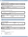
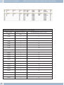
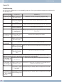
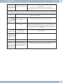
Number of Voiceboxes and free recording time for each Voicebox
The number of available Voiceboxes and the recording time available depend on the capacity of the Compact Flash
Card used in the system. The maximum number of Voiceboxes is defined in the table below, based on the capacity of
the Compact Flash Card. This number is specified in the PC configuration, but only when configured Voiceboxes are
active.
Note
If you have configured fewer Voiceboxes than the maximum number, the available storage (recording) capacity is
distributed among these Voiceboxes. Around half of the total storage space is reserved for WAV files (melodies)
that are stored on the CF Card (with 16 MB ~ 8MB, with 512 MB ~ 256 MB). If the available storage capacity for the
Voicebox is exhausted, the caller will hear a busy signal at the beginning of the announcement. Further recording
and a sign-off announcement are not possible.
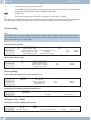
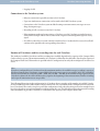
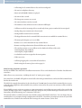
The following illustration in the configuration for «Voicebox« shows examples of the number of available Voiceboxes for a 64 MB (top) and a 1GB (bottom) Compact Flash Card. The screen mask for the Configurator shows the number of Voiceboxes that can be set up for a particular configuration. Only subscriber 20 is given in the example shown
here; this subscriber can use the maximum recording time in this case. The table below shows the potential recording
time and number of possible Voiceboxes as a function of the capacity of the Compact Flash Card.
29
Voicebox (Answering machine)
Number of Voiceboxes and free recording time for each Voicebox
Number of Voiceboxes and free recording time for each Voicebox
30
Storage capacity
Number of Voiceboxes
Recording time per Voicebox in minutes
8 MB
none
—
16 MB
1
8
32 MB
1
16
32 MB
2
8
64 MB
1
32
64 MB
2
16
64 MB
3
10,7
64 MB
4
8
128 MB
1
64
128 MB
2
32
128 MB
3
21,3
128 MB
4
16
128 MB
5
12,8
128 MB
6
10,7
128 MB
7
9,1
128 MB
8
8
256 MB
1
64
256 MB
2
64
256 MB
3
42,7
256 MB
4
32
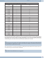
Number of Voiceboxes and free recording time for each Voicebox
Voicebox (Answering machine)
Number of Voiceboxes and free recording time for each Voicebox
256 MB
5
26,5
256 MB
6
21,3
256 MB
7
18,3
256 MB
8
16
512 MB
1
64
512 MB
2
64
512 MB
3
64
512 MB
4
64
512 MB
5
51,2
512 MB
6
42,7
512 MB
7
36,6
512 MB
8
32
1 /2 GB
1
64
1 /2 GB
2
64
1 /2 GB
3
64
1 /2 GB
4
64
1 /2 GB
5
64
1 /2 GB
6
64
1 /2 GB
7
64
1 /2 GB
8
64
If you change the Compact Flash Card while the system is in operation the number of Voiceboxes will be adapted to
the capacity of the new card. For example, if you have configured the Voicebox system for a 128 MB card and then install a 64 MB card, the Voiceboxes that were configured last will be de-activated automatically. If you then install a
128 MB card again at a later time, the de-activated Voiceboxes will then be re-activated.
Note
Up to 99 messages can be stored in each Voicebox (depending on the capacity of the Compact Flash Card being
used). Messages that are shorter than 2 seconds are not recorded. For example: A caller ends the call after the request signal without actually leaving a message.
The Voicebox will be de-activated automatically if its recording time has been exhausted. The Voicebox can be re-activated after messages have been listened to and deleted.
Note
Compact Flash Cards with Microdrive are not supported.
31
Voicebox (Answering machine)
Settings for a Voicebox
Settings for a Voicebox
Announcements and operating modes
An announcement text (greeting message) and information texts can be stored. These announcements are spoken
over the phone. In the mode »Record« a caller will hear the announcement text and can then leave a message after the
signal. The caller will hear the information text in the mode »Announcement only«. In this mode it is not possible to
leave a message.
As with the call modes for teams, a distinction is also made between a Day and Night mode for Voiceboxes. You can
define different settings (mode, time until call is accepted) for both modes. Switchover between the modes »Day«
and »Night« is made by entering a code on the phone, or is carried out automatically by a calendar function in the
PABX system.
In the default settings for the PABX system a greeting and sign-off text have already been stored in the PABX memory. These texts can not be changed through configuration. The sign-off announcement is always used for all Voiceboxes when there is less than 10 seconds recording time available for a Voicebox. When the maximum recording time is
set, the busy signal is heard at the end of this period, and not a sign-off message.
Note
Own welcome texts or sign-off messages you record will overwrite the default recordings. When you delete your
own texts the system will automatically reload the factory default texts.
Operation
A Voicebox can be operated from any internal or external telephone. Operation is safeguarded by an individual
4-place PIN (initial (default) setting »0000«). Recording of announcements, listening to messages or changing settings can only be carried out after entering this PIN. To operate a Voicebox from an external telephone (remote location), the remote operation function for the Voicebox must first be enabled in the configuration.
Configuration
Voiceboxes are configured in the PC configuration program. You can make all necessary settings for Voiceboxes
with this program. By entering the appropriate codes at a telephone you can set the mode (Day / Night), record announcements/information texts, or listen to messages.
Using the Voicebox at a phone
Using the Voicebox at an internal phone
You can use the Voicebox either from an assigned, internal phone, or from any arbitrary internal phone. Once you
have set up the connection to the Voicebox you can listen to messages, conduct configuration or record announcements / information texts. Use of all Voiceboxes is protected by individual PINs. Should you forget your PIN you can
reprogram it through PC configuration.
Activating / De-activating a Voicebox from an assigned telephone
You can activate or de-activate a Voicebox from an assigned telephone. A team Voicebox can be activated by any
team member using the team number. When a Voicebox is activated the system automatically checks whether an announcement or information text has been saved for the selected mode and whether more than 10 seconds recording
time is available for that Voicebox. An active Voicebox is de-activated automatically if there is less than 10 seconds
free recording time available for that Voicebox.
Activating a subscriber Voicebox
b
Lift up the handset of your phone. You will hear the internal dial tone.
*
#
32
Press the asterisk key (*) to activate the unit.
Press the hash key for deactivating.
Logging of calls
30#
q
a
Voicebox (Answering machine)
Dial this code. Confirm your entries by pressing the hash key.
You will hear the positive acknowledgement signal.
Replace the handset.
Activating a team Voicebox
b
Lift up the handset of your phone. You will hear the internal dial tone.
*
#
30*
t
#
q
a
Press the asterisk key (*) to activate the unit.
Press the hash key for deactivating.
Dial this code.
Enter the team number.
Confirm your entries by pressing the hash key.
You will hear the positive acknowledgement signal.
Replace the handset.
Logging of calls
An internal subscriber that has been allocated a Voicebox may record calls. The Voicebox does not have to be activated to record a call. Recording can not be performed if the recording time for a Voicebox is exhausted. In this case the
call is briefly disconnected and you will hear the negative acknowledgement signal.
A team Voicebox can not be used for recording.
Before recording a call let your calling partner know that you are activating the recording function so that he/she can
consent.
After you enter the code for recording a call the call will be recorded until:
· The code for ending of recording is entered.
· The call is ended by hanging up the handset.
· There is no longer any recording time available on the Voicebox.
Recording calls at an ISDN phone
g
You are conducting a call and would like to record it.
t
*33
Switch the phone to Keypad.
Enter this code to begin recording.
The call will then be recorded.
#33
g
Enter this code to end current recording.
Continue with your call.
Recording a call at an analog phone
g
You are conducting a call and would like to record it.
r
*33
g
r
#33
g
Press the R key. You will hear the internal dial tone. The caller is on hold.
Dial this code.
Continue with your call. The call will now be recorded.
Press the R key. You will hear the internal dial tone. The caller is on hold.
Enter this code to end current recording.
Continue with your call.
Note
Recording is terminated automatically when you hang up the handset while recording a call.
33
Voicebox (Answering machine)
Using a Voicebox at an assigned phone
Using a Voicebox at an assigned phone
Notification of new message in Voicebox
When new messages are present on the Voicebox:
When the internal party hears the special dial tone for teams instead of the internal dial tone, you can
specify in the configurator, whether this tone is to be heard by just one team member or by the entire
team.
On analog devices, the subscriber hears a short signal tone, when a new message has been received.
When the call waiting tone has been enabled on system telephones the message will be signaled using
this tone.
The »MWI« LED - if fitted - lights up. This setup is carried out in the configuration.
A special text or symbol will be shown on the display of the phone ( e.g. *39#).
To receive these tones and displays »Voicebox MWI« must have been set up for that particular extension.
The team member that is notified when there is a new message in the Voicebox must be defined in the Voicebox configuration for a team Voicebox.
Listening to messages / recording calls
The oldest message is always played back first. All of the messages are then played back from oldest to newest. If no
newer messages are present you will hear the negative acknowledgement signal. A new message counts as having
been played back even if you only listened to part of the message.
Procedure for entering the Voicebox menu
You only need to enter the following procedure
one time; after that you can utilize all the procedures
described in the following one after the other. After entering this procedure wait around 3 seconds before entering any other codes. You can always press the number key (#) and enter the following code to return to the beginning of the menu.
b
*39#
q
t
#
q
Lift up the handset of your internal phone.
Select the procedure for the Voicebox.
You will hear the positive acknowledgement signal.
Enter the PIN for the Voicebox (default setting 0000).
Confirm your entries by pressing the hash key.
You will hear the positive acknowledgement signal.
After entering this procedure wait around 3 seconds before entering any other codes. The Voicebox
codes are given under »Quick reference guide for Voicebox « (Page73 ).
Note
You will be returned to the main menu immediately when you press the number key (#) while a function is being
executed, for example »Listen to new messages«. If, in the example shown here, you have finished listening to a new
message and then press the number key (#) you will hear the negative acknowledgement signal even though you are
still located in the main menu.
34
Procedure for entering the Voicebox menu
Voicebox (Answering machine)
Listening to new messages or to recorded calls
1
Dial this code. Thenewmessagesarethenplayed backoneafter the other, with eachonebeing separated by the positive acknowledgement signal.
If no new messages are present you will hear the negative acknowledgement signal and are returned
automaticallytothebeginningoftheinputprocedureagain,asifyouhadpressedthenumberkey(#).
Then, select the function while the message is being played back:
1 Listening to the next message (end the message you have just listened to and listen to the next one in
the sequence.
2 Repeat the message just listened to (the message that you have just listened to is repeated).
3 Delete the message just listened to (the message that you have just listened to is deleted).
Listen to old messages or recorded calls
2
Dial this code. Older messagesare played back one after the other, each one separated by a positive acknowledgement signal.
If no older messages are present you will hear the negative acknowledgement signal and are returned
automaticallytothebeginningoftheinputprocedureagain,asifyouhadpressedthenumberkey(#).
Then, select the function while the message is being played back:
1 Listen to next message.
2 Repeat message just listened to.
3 Deleting of the last message that was listened to
Delete all saved messages and recorded calls (new ones and ones that have already been played back)
3
Dial this code. You will hear the positive acknowledgement signal.
* Press the asterisk key; all messages that have been listened to previously will be deleted.
q
You will hear the positive acknowledgement signal.
Activating/De-activating the Voicebox
4
Dial this code.
Then select the desired function:
0* Activating the Voicebox in the current mode.
00 Deactivate Voicebox.
q
You will hear the positive acknowledgement signal.
Activating the Voicebox in the »Day« or »Night« call mode
4
Dial this code.
Then select the desired function:
01 Activating the Voicebox in the »Day« call mode.
02 Activating the Voicebox in the »Night« call mode.
q
You will hear the positive acknowledgement signal.
35
Voicebox (Answering machine)
Procedure for entering the Voicebox menu
Configuring the »Day« call mode.
Dial this code.
4
Then select the desired function:
10
11
12
13
14
15
Deactivate Voicebox.
Activate the Voicebox, calls taken immediately.
Activate the Voicebox, calls taken after set time (delayed)
Activate voicebox on busy
Activate voicebox on busy an by time (delayed).
ActivatetheVoiceboxasanansweringmachine.Thecallerhearstherecordedannouncementandcan
then leave a message.
17 Activate the Voicebox for announcement only. The caller hears the recorded announcement and can
then leave a message.
q You will hear the positive acknowledgement signal.
Configuring the »Night« call mode.
4
Dial this code.
Then select the desired function:
20
21
22
23
24
25
Deactivate Voicebox.
Activate the Voicebox, calls taken immediately.
Activate the Voicebox, calls taken after set time (delayed)
Activate voicebox on busy
Activate voicebox on busy an by time (delayed).
Activate the Voicebox as an answering machine.. The caller hears the recorded announcement and
can then leave a message
27 Activate the Voicebox for only one announcement. The caller hears the recorded announcement and
can then leave a message.
You will hear the positive acknowledgement signal.
q
Listening to or recording announcements
5
Dial this code.
Then select the desired function:
1
2
q
0
50
Listening to saved announcement texts.
Recording an announcement.
You will hear the positive acknowledgement signal.
Dial »0« to end recording.
Dial »50« to accept the announcement text.
Listening to or recording information texts
5
Dial this code.
Then select the desired function:
4 Listening to saved information texts.
5 Recording an information text.
q You will hear the positive acknowledgement signal.
36
Use from any internal telephone
Voicebox (Answering machine)
0 Dial »0« to end recording.
50 Dial »50« to accept the information text.
Changing the Voicebox PIN
9
Dial this code.
Then select the desired function:
1
t
*
t
#
q
a
Changing the Voicebox PIN.
Enter the new PIN (4 characters).
Confirm your entry by pressing the asterisk key.
Enter the new PIN (4 character) again.
Confirm your entry by pressing the hash key (#).
You will hear the positive acknowledgement signal.
Replace the handset.
Note
The Voicebox codes are given under »Quick reference guide for Voicebox « (Page73 ).
Use from any internal telephone
b
Lift up the handset of your phone. You will hear the internal dial tone.
*39*
t
#
q
t
#
q
t
Dial this code.
Enter the number for the Voicebox (number for internal subscriber or team number).
Confirm your entries by pressing the hash key.
You will hear the positive acknowledgement signal.
Enter the PIN for the Voicebox.
Confirm your entries by pressing the hash key.
You will hear the positive acknowledgement signal.
The Voicebox codes are given under »Quick reference guide for Voicebox « (Page73 ).
Remote control of Voicebox from an external phone
To use a Voicebox from a remote location remote polling must be enabled in the configuration and the 4/place PIN
for the Voicebox changed individually (from default setting).
Remote control by dialing up the Voicebox
b
Lift up the handset of your phone (external subscriber).
t
Dial the number that is assigned to the internal subscriber or team. Wait until the Voicebox has taken
the call.
Set your phone to frequency (DTMF) dialing, or use a DTMF manual transmitter.
*39#
q
t
#
Dial this code.
You will hear the positive acknowledgement signal.
Enter the PIN for the Voicebox.
Confirm your entries by pressing the hash key.
37
Configuring the Voicebox using a system phone
q
t
Remote control of Voicebox from an external phone
You will hear the positive acknowledgement signal.
The Voicebox codes are given under »Quick reference guide for Voicebox « (Page73 ).
Remote control using remote polling function for PABX system
If remote polling has not been enabled via PC configuration »General«, the function must be enabled
using »Enable/Inhibitremoteaccess«viaaninternaltelephone. YoucanthenactivateanduseVoiceboxes from remote locations.
b
t
Lift up the handset of your phone (external subscriber).
Dial the numberthat is assignedto the internal Service numberfor the PABX system(point-to-multipoint access: MSN / Point-to-point connection: pabx number+direct dial-in).
If remote access has been enabled you will hear the special dial tone of your PABX.
Set your phone to frequency (DTMF) dialing, or use a DTMF manual transmitter.
t
q
*39*
t
#
q
t
#
q
t
Enter the 6-digit password (PIN2) for your PABX.
You will hear the acknowledgement signal for approximately one second.
Dial this code.
Enter the number for the Voicebox (number for internal subscriber or team number).
Confirm your entries by pressing the hash key.
You will hear the positive acknowledgement signal.
Enter the PIN for the Voicebox.
Confirm your entries by pressing the hash key.
You will hear the positive acknowledgement signal.
The Voicebox codes are given under »Quick reference guide for Voicebox « (Page73 ).
Configuring the Voicebox using a system phone
If you have an elmeg CS410 or elmeg CS400xt system telephone connected to your PABX system you can configure
and use a Voicebox in these systems using a special menu available in the system telephones.
This special menu for using the Voicebox is provided in the elmeg CS410 system telephone. The number / team number for the Voicebox must be stored in the telephone to use this function. When the phone is idle the softkey »Voicebox« is displayed. When this softkey and the call LED flash, this indicates that new messages have arrived at the assigned Voicebox. You can open the PABX system Voicebox menu by pressing this softkey. In this menu you can listen to
messages or make further input / set the configuration for the Voicebox.
This menu, along with the functions it contains for using and configuring the Voicebox, is managed in the PABX system.
Note
The special menu for convenient use can only be used for one Voicebox at a telephone.
You must install an optional Compact Flash Card in the PABX system to use the integrated Voicebox system.
Note
First, you must assign and configure a Voicebox for an internal subscriber under »Voicebox« in the configuration.
Only then can you utilize the following setup procedure.
38
Remote control of Voicebox from an external phone
Configuring the Voicebox using a system phone
Configuring a number for the Voicebox in the system telephone
The number of your Voicebox must be stored in the system telephone. You can input this number using the PC configuration program for the system telephone, or using the system telephone as described below.
Begin as follows:
a
M
s
>
s
Configuration
t
Enter the number for the Voicebox and confirm
with OK (in the example shown here: 21).
Voicebox
ˆ
Voicebox number
ˆ>21_
Entering the Voicebox menu
After you have stored the number for your Voicebox in the system telephone the softkey »Voicebox« is then added to
and shown in the display when the phone is idle. When new messages are present in the Voicebox the Voicebox softkey begins flashing, along with the call LED of the system telephone. In addition, the number of new messages is also
shown in parentheses behind the »Voicebox« softkey.
s
The telephone is idle. Press the »Voicebox« softkey.
12.12.02 07:41
}
Info
Voicebox
Telephone directory
Idle
VIP
Caller list
Note
The Voicebox is activated when a checkmark »˜« (as shown in the top display) is displayed behind the word »Voicebox.
s
If the PIN is still set to the default setting (0000) the
Voicebox menu can be opened by pressing the
»Voicebox« softkey. If the PIN has been changed
you will first be asked to enter the PIN
Voicebox
Please enter
PIN:
-
s
The menu that is displayed is controlled by the
PABX system and can be used for operating and
configuring the Voicebox whose number has been
stored in the telephone.
Voicebox = On {}
Messages.........
..............Anncs
Day settings ....
..Night settings
General............
..........OFF
To open one of the menus displayed,
39
Configuring the Voicebox using a system phone
Settings for the »Day« and »Night« modes
· press the corresponding softkey next to the desired menu.
or
· Use the arrow keys to select the desired menu and confirm your selection with OK
Recording announcements
You can record two different announcements (announcement text and information text) for each Voicebox. The
length of the two announcements is subtracted from the available recording time for that Voicebox. In brief this means that the longer the two announcement texts, the less free storage space that is available for leaving messages.
Begin as follows:
s
s
Voicebox
Anncs.
a
s
Select the desired menu item. Depending on the
menu item, further selections / settings or input
can be made.
Anncs
{}
announcement...
.............Infotext
A caller hears the announcement text in the »Record« mode.
»Infotext«
A caller hears the information text in the »Announcement only« mode.
In this menu you can listen to or delete an existing announcement/information text, or record a new text. A newly recorded announcement/information text is stored in the PABX system only after you press the softkey »accept«.
»Announcement text«
Settings for the »Day« and »Night« modes
As with the call modes for teams, a distinction is also made between a Day and Night mode for Voiceboxes. You can
define different settings for both of these modes.
You can also change the active mode in this menu (»Day« to »Night« and vice versa). You can recognize the active
mode here (Day/Night) by the fact that the other (inactive) mode will be offered for you to select for changing. In the
example shown here the »Night« mode is active. You can select this menu item to switch to the »Day« mode.
Begin as follows:
s
s
Voicebox
Day setttings or Night settings
a
s
Select the desired menu item. Depending on the
menu item, further selections / settings or input
can be made.
»Status.....
»OFF«
»per time«
40
Settings Day
{}
Status after: 30 sec...
...Mode: Speak
Activate Night.....
Here, you define the time period during which the Voicebox is to take calls in
the selected mode (»Day« or »Night«).
The display shows: »Status: off « The voicebox is not active.
The display shows: »Status after 15 seconds«. Time options available »5, 10,
15, 20, 25 s, 30 s«.
General settings
Configuring the Voicebox using a system phone
The display shows: »Status 15 seconds + Busy«. The available options are
«Busy« and Time »5, 10, 15, 20, 25 sec, 30 sec«.
The display shows: »Status on busy«. Activate when user is busy.
The display shows: »Status immediately«. The call is transferred to the voicebox right away.
You can choose between two different operating modes for each call mode
(»Day« or »Night«) for using the Voicebox.
The display shows: »Mode: Speak«: In this operating mode the caller will hear
the announcement text and can then leave a message after the signal.
The display shows: »Mode: Voice announcement only«: In this operating
mode the caller will hear the information text. In this mode it is not possible to
leave a message.
You can select this menu item to switch the Voicebox over to the other (inactive) mode.
»Time + Busy«
»on busy«
»immediately«
»Mode: «
»Speak«
»announcement only«
»Activate Night«
»Activate Day«
General settings
The general settings apply to the Day and Night modes for the Voicebox.
Begin as follows:
a
s
s
s
Voicebox
General
Select the desired menu item. Depending on the
menu item, further selections / settings or input
can be made.
»Msg. length: «
»Message 10«
»Access-PIN«
»Remote polling«
General
{}
Msg. length:30 sec...
........Message 21
Access-PIN..........
.....Remote polling: Ok
Define the time available to a caller for leaving a message. For example: »30
sec.«, »60 sec.«, ».«, »90 sec.«, »120 sec.« or »max«.
Here, you define which internal subscriber (ext. 10 in this example) is to be informedwhennewmessagesarepresentontheVoicebox.Notificationofanew
messageismadebyplayingaspecialdialtoneatthecorrespondingsubscriber.
Notification on system telephones configured with access to a Voicebox is in
the form of a flashing call LED and flashing softkey »Voicebox«.
Here, you can change the PIN for your Voicebox. The Voicebox is protected
againstunauthorizedaccessbyaPIN.ThePINmustbeinputfromatelephone
during operation / remote control of the Voicebox.
You can define whether your Voicebox can be used from a remote location.
Using remote access you can listen to messages from a remote location, or
make configuration settings for the Voicebox (for example, activating/de-activating the Voicebox).
Listen to messages
The oldest messages or recorded calls are always played back first. The date and time and number of the caller (if
available) are displayed for each message. Recorded messages can be deleted while they are being played back.
41
Configuring the Voicebox using a system phone
Listen to messages
Begin as follows:
a
s
s
s
Voicebox
Messages
Select the desired menu item. Depending on the
menu item, further selections / settings or input
can be made.
Messages
{}
New: 02 Calls.......
.......Old: 07 Calls
Recordings: 00......
Delete..............
»New: Calls«
»Old: Calls«
»Recordings:«
»Delete«
The new messages are then played back one after the other. All messages are
played back one after the other. A new message counts as having been played
back even if you only listened to part of the message. Messages that have been
listened to are placed automatically in the list of older messages.
Messages that have been listened to are played back one after the other. All
messages are played back one after the other.
Recordedcallsareplayedbackoneaftertheother.Allstored,recordedcallsare
played back one after the other.
You can use this to delete all the messages in the Voicebox that have been listened to. Deleting of messages may require several seconds, depending on the
storagetimeusedbythemessages(quantityandlengthofthestoredmessages.
Note
It is meaningful to regularly delete messages that have already been listened to in order to make room for new messages.
42
Commissioning the phone part
Commissioning the phone part
Phone number plan
When you start up your PABX for the first time a number of settings are already pre-configured (default settings).
This includes the internal numbers. This means that you can place calls immediately after switching on your PABX.
Internal numbers:
· Numbers 20...29 are set for the »Connection of ISDN terminal devices« on the internal ISDN bus.
· The internal numbers 10…17 are provided for analog ports, numbers 30…39 for CAPI and numbers 40…43 for the DSL-router.
· Internal service number: The internal number 55 has been assigned as the service number. This
number is used to provide access for the PC to the PABX system via the internal ISDN connection.
You can configure the PABX via the internal ISDN connection and a PC with an ISDN card.
· External service number: An MSN or, with a point-to-point access, a direct dial-in number is assigned to the internal service number 55 during PC configuration. This »external service number« is the only access possible for configuring »Follow me« and »Room monitoring« from an
outside location.
· Team 00: In the initial state the numbers 10, 11 and 20 are entered and enabled for Team 00 in the
day/night team call allocation.
Default setting
· The external ISDN connection is set to point-to-point access.
· The four-digit PIN1 (password) is set to 0000.
· The six-digit PIN2 (password) is set to 000000.
· Assignment of an external ISDN connection is made by entering 0.
· The internal ISDN bus is configured as »internal S0 bus«.
· The switchable call mode for Team 00 is set to »Day mode«.
· The group call is set for »simultaneous«.
· The switching privilege for teams is configured for no terminal device.
· All users are in Pick-up group 00.
· Accepting (pick-up) of a call is possible for all terminal devices.
· All subscribers can use the telephone directory.
· No terminal device is authorized for SMS reception.
· The analog connections are configured for telephones that use DTMF dialing and a flash key (200
ms).
· The active terminal devices are authorized for international calls.
· The dial range is not configured.
· The number of the caller is displayed (caller ID).
· The B number is transmitted to the caller.
43
Commissioning the phone part
· Call waiting for a/b terminal devices has not been configured.
· No entries in telephone directory.
· Music on hold (MOH): Melody 1 is played.
· No time or date is stored.
· The charge rate counters are set to 0.
· No connection data records are stored.
· The numbers in the call data records are shown in full length.
· Call data records for incoming calls are stored only when a project number has been assigned.
· Analog charge rate transmission is deactivated.
· Analog number transmission is activated.
· The keypad function for the external ISDN connection is not enabled for terminal devices.
· The meter pulse frequency is set to 16 kHz.
· Remote access can be initiated from any terminal device.
· Remote switching authorization (External follow me) is deactivated.
· The switchover times are set as follows in the calendar for all days of the week:
Switching Night / Day: 8:00 AM,
Switching Day / Night: 4:00 PM
· A calendar has not been assigned to the team options.
· LCR is not active.
· Call charge logging is de-activated for all subscribers.
· Initial setting for the router, please refer to page 59.
Initial startup (telephone operation)
Install your PABX as described in the installation instructions. These can be found on the CD under »Installation instructions«.
Make all necessary connections, including the 230 V AC mains power supply.
In its initial state, the PABX will signal an external call at the analog terminal devices and at the ISDN terminal device
that has the number 20.
The MSNs (for example the numbers for the subscribers in Team 00) must be entered in the terminal devices to ensure that the other telephones and terminal devices you have connected to the system can continue to all be reached by
external parties.
If your PABX system is set for use at a point-to-point connection it is crucial that you enter your local area code in the
Section »Dialing region« in PC Configuration. Only after doing this can you take advantage of features such as »Call
forwarding« (Partial Rerouting) and »Automatic Call-back«.
The internal numbers (or MSN extensions) have default settings in the PABX’s initial state. You can change these internal numbers as you require through configuration with the PC. Consult the operating instructions for your ISDN
terminal devices to find out how and with which settings the various features can be used.
44
Commissioning the phone part
Note
Your PABX supports the flash function for analog telephones. Therefore, never just briefly replace the handset or
press the button in the cradle briefly with your hand, as the PABX would take this as a flash signal instead of hanging
up.
45
Configuring performance features using a telephone
Service access
Configuring performance features using a telephone
Various settings are protected by PIN1 in the PABX. In the default state, this PIN 1 is set to 0000. Write down your
PIN 1 and keep it in a safe place, because if you forget or lose your PIN 1 you will no longer have access for configuring
the PABX over a telephone.
»Remote access / remote control« is protected by PIN 2.
Remote access using this 6-digit PIN2 is only possible when this PIN2 has been changed individually, i. e. it is no longer in its initial setting of 000000.
Service access
This feature enables you to have the PABX configured by your dealer’s service center or download the current software of the PABX. You can trigger this function from an internal phone of your PABX or release your PABX for access by
an external PC (for example your specialized dealer).
Outgoing service call (solution with 2 B-channels)
g
You call the service center. You are connected with the service technician who then explains the further procedure to you.
R
*792
WhenrequestedbythetechnicianyoupushtheRecallflashbuttonYouwillheartheinternaldialtone.
Dial this code .
If you wish to establish a service connection with the services maintenance and diagnosis, enter the
code number*794.
Dial the number of the service center.
t
#
q
g
Finish input.
You will hear the positive acknowledgement signal.
You are then re-connected with the service technician and can continue your call.
Outgoing service call (access via 1 B channel)
b
*792
t
#
Number for the
service center
Lift up handset
g
a
Connection with
service center
Replace
handset
You will hear the internal music on hold once a connection to the service center has been established.
When the data have been transferred the service center will terminate the connection. You hear the busy signal.
Ending an active, incoming service link
You can terminate a connection set up by the service center using the following procedure.
b
#792
Lift up handset
q
a
Ack. signal
Replace handset
Enabling for remote service access
You can release your PABX system for remote access by an external subscriber. Release for remote access of the
PABX is effected for 30 minutes.
b
Lift up handset
*782
q
a
Ack. signal
Replace handset
Enabling for remote service access (no checking of subaddress)
You can release your PABX system for remote access by an external subscriber. Release for remote access of the
PABX is effected for 30 minutes.
46
Setting features using a telephone
b
Configuring performance features using a telephone
#782
Lift up handset
q
a
Ack. signal
Replace handset
Deleting authorization for remote service access
You can cancel a programmed release for incoming remote access any time you want. However, an existing connection to a service center is not terminated.
b
#799
Lift up handset
q
a
Ack. signal
Replace handset
Setting features using a telephone
After you begin configuration you can set the features for your system using the codes described here. The telephone
being used for programming can not be reached while the system is being configured.
You will hear the positive acknowledgement signal once you successfully conclude configuration for a setting. You
can then move on to configure the next setting. If you wait for more than 40 seconds between one entry and another,
the PABX will terminate configuration and you will hear the busy signal. All input made up to that point which was
concluded with a positive acknowledgement signal will be saved when you hang up the handset. Saving is performed
for 10 seconds after you hang up the handset. During this period it is important that you do not begin a new configuration of the system, and that power is not interrupted to the system.
You must perform the following procedure at the beginning of each subsequent configuration process.
b
**
Lift up handset
q
====
q
Ack. signal
Enter PIN 1
Ack. signal
Changing PIN 1 or PIN 2
You can prevent misuse of your PABX by other parties by implementing various security functions. Your PABX settings can be protected using your 4-digit PIN1 (code number). Access by external parties (remote access) is protected
using your 6-digit PIN2.
PIN 1 (4-digit): Security precaution against misuse of your PABX by other parties.
PIN1 is a 4-digit code number that is required when you wish to protect your system settings against unauthorized
access.
PIN 2 (6-digit): Security for settings made from external telephones
For the settings:
· Call forwarding (Follow me) from external location
· Room monitoring from external location
prevent unauthorized parties from using your PABX. Only after you enter this 6-digit PIN2 are you allowed to utilize
functions in your PABX that can be activated/deactivated from external telephones.
Note
Remote access using this 6-digit PIN2 is only possible when this PIN2 has been changed individually, i. e. it is no
longer in its initial setting of 000000.
911
Change PIN 1
(4-place)
or
912
t
t
q
Change PIN 2
(6-place)
Enter new
PIN
Enter new PIN
(confirm)
Ack. signal
47
Configuring performance features using a telephone
Setting features using a telephone
Activating Least Cost Routing (LCR)
781
2/#
q
Code
Enabling / Inhibiting LCR
Ack. signal
Remote access / remote control: enable / inhibit
780
*/#
q
Code
enable / inhibit
Ack. signal
Setting the date and the time
98
Code
=!x§! =!x!" ==x)) ==x"§ ==x%)
Day
Month
Year
Hours
q
Minute
Ack. signal
Deleting the charge counter for one internal subscriber or for all
850
Code
t
or
*
internal number or * for all internal
extensions
Setting up call accounts
830
t
t
#
Code
Int. extension number
amount (max. 6-place, with
a factor of 1000)
q
Ack. signal
Deleting call accounts
830
t
Code
Int. extension number
#
q
Ack. signal
Activating / deactivating an extension’s call account
890
t
*/#
q
Code
Int. extension number
Activate / Deactivate
Ack. signal
Resetting settings to default state (Reset)
999
Code
Resetting one internal extension or all
48
900
t or *
q
Code
internal number or * for all internal
extensions
Ack. signal
Initial startup
Commissioning an IP-phone for a DSP module
Commissioning an IP-phone for a DSP module
Whenyour PABX is equipped with an optional DSP module.After your PABX system has run up it will recognize the
module and you can then begin configuration at the IP phone.
Note
This short description is based on the DHCP set up in the PABX.
The elmeg IP290 is used as an example in this description.
Note
An instruction manual describing all currently available features can be found on the CD-ROM.
Initial startup
Connect the pabx to the IP telephone using the network cable. Connect the plug-in power supply unit and the telephone and switch the power on.
Language setting
Select Language:
{
English
}
Use the arrow keys <> to select the language . Press O to confirm.
Select Language:
{
Deutsch
}
Selecting a calling tone
Use the arrow keys <> to select the country. Press O to confirm.
Dial tone:
{
Australia
Dial tone:
{
Deutschland
}
Select a time zone
Select a time zone using the arrow keys <> . Press O to confirm.
Dial time zone:
{ -10 USA (Honululu) }
Dial time zone:
{+1:Deutschland(Berlin}
First log-in
A user must have been set up in the pabx.Enter your user ID (for example for MSN22 ) which consists of the MSN extension, followed by an “@” and the IP_ address for the PABX.
ID:
[email protected]
Enter an ID for the MSN22 and the IP address 192.168.1.250:
22*11**192*1 **168*1**1*1**250
49
Commissioning an IP-phone for a DSP module
Initial startup
After entering your user ID confirm it by pressing the O key.
12/30 (22)
10:22 AM
Idle
Telbook
Lists
You will be asked to input the log-on PIN, if htis security feature has been set up for your PABX.
After you have logged on successfully you will see the new number (22) in the display.
50
PABX and PC
PABX and PC
A CD containing the Windows configuration program and other software and drivers is included in the PABX package.
Note
The first time you start the Configurator you will be asked to enter your user ID and password. Use »Service« as your
user ID and also »Service« as the password. Please note that these words are case-sensitive! Once you’ve been logged
on to the Configurator you can change your user ID and password as you like.
Contents of the CD-ROM
In these operating instructions we would like to give you a brief summary of the software included in the scope of
supply for the system. The software programs themselves are not described in these instructions. Should any questions or problems arise while you are using the programs you can use the online Help function for assistance. All
programs are equipped with a comprehensive online Help function.
Programs for configuring the PABX
Professional Configurator:
The settings for the individual features of your PABX are made in the PABX configuration. You can configure your
external MSN and assign these numbers to individual, internal users, or to a team consisting of several users (members). You can also assign a name for each individual, internal user and configure the various features separately
(such as authorization privileges, exchange line access, cost logging, etc. ), or you can apply the settings of one user to
those for a different user. Configuration is also used to define the calendar, numbers for call control (unrestricted
numbers, restricted numbers) and emergency or direct calls. You can also make general settings for the PABX, for
call data logging or for remote access to the PABX system.
Charge Manager:
You can use the charge manager program for logging connection data for reading out or clearing call data records
stored in the PABX and user-specific counters. The call data records that are read out can be evaluated using various
sorting and filtering functions, or exported for processing in other programs.
For example: Sorting functions allow you to compile data records according to internal users, project numbers or
numbers that are dialed/transferred. The filtering functions can be used to display data records containing individual properties. You can set these filtering functions to fit your specific needs.
Telephone Directory Manager:
The PABX system is equipped with an integrated telephone directory, in which you can store up to 500 numbers,
with their associated names. You can access the PABX telephone directory with all phones connected with the system. System telephones can also use the PABX menu. Other telephones can use a code to dial from the telephone directory. Entries are added to the directory using the Telephone Directory Manager on the CD. The import/export
function of the telephone directory manager allows imported or exported data to be edited and processed in other
programs.
ControlCenter:
The Control Center monitors the activities of the router for establishing and severing a connection. It indicates for
instance: the provider used for the current connection, the type of connection (ISDN or DSL), the IP address, the duration, the port, the up- or downloaded data volume. You can also terminate an ongoing connection or establish a
new one.
Download Manager:
Using this program you can load new system software via your PC into the PABX. You can load new software via the
integrated USB port, or via the Ethernet port »LAN« of your PABX system. If an ISDN card is already installed in your
PC you can also update the system software via the internal ISDN connection of the PABX.
51
PABX and PC
Application programs
TAPI-Configurator:
Using TAPI Configuration you can adapt the TAPI driver for a program that uses that driver. You can also check
which MSN is assigned to which terminal device, define new line names and can set the dialing parameters.
First configure the PABX. Then, you must configure the TAPI interface. Use the program »TAPI Configuration« in
the WINTool Launcher.
LCR Professional
Both provider and routing tables can be prepared and edited individually using this new LCR procedure. This LCR
procedure can be configured using the Web-based PC program supplied with the system.
You can activate/de-activate the LCR procedure using either the »Professional Configurator«, or a code sequence on
the telephone.
Application programs
Adobe Acrobat Reader:
Program for viewing and printing PDF documents.
Drivers
USB driver (Universal Serial Bus)
Recognition and control for the PABX system after being connected to the USB port of your PC. The USB driver is installed as a virtual network card that uses the TCP/IP protocol.
TAPI in the LAN:
The package includes a program called »TAPI for LANs« for use in your network. This software can be installed on
any PC in the network. This gives you the possibility of running your TAPI application from a central location via an
interface, i. e. the PABX system. There is no ISDN card required for the PCs. Please note that software used for the
TAPI application may require certain license agreements with the software manufacturer. Up to 10 users, the program »TAPI in LAN« does not require a license to run.
CAPI in LAN:
The package includes a program called »CAPI for LANs« for use in your network. This software can be installed on
any PC in the network. This gives you the possibility of running your CAPI application from a central location via an
interface, i. e. the PABX system. There is no ISDN card required for the PCs. Please note that software used for the
CAPI application may require certain license agreements with the software manufacturer. Up to 10 users, the program »CAPI in LAN« does not require a license to run.
Installation instruction for Windows 98
If you have Windows 98 installed on your PC you must observe the following installation instructions for the USB
driver. Keep the original Microsoft Windows 98 CD handy.
Initial installation
Connect your PC to the USB port of the PABX system via the USB cable and switch on both devices. Insert the CD
supplied with the system. The Windows 98 hardware assistant is then started.
Installing the driver:
· A »Composite USB device« is then recognized.
· Click »Next«
· Select »Search for the best driver for your device. (Recommended)« and then click »Next«
· Select »CD-ROM drive« and then click »Next«
· Select »Updated driver (recommended)«.
· Select »elmeg USB Remote NDIS Network Device« and click »Next«
· Click »Next« once again to install the USB driver.
52
Drivers
PABX and PC
· Press the »Finish« button
Note
When the installation has been performed correctly, the following entry will appear in the device manager under
the list of network cards: »elmeg Txxx USB Remote NDIS Network Device«.
Removing the default driver
If you have not installed the elmeg USB driver, the standard driver for »Composite USB device« will be installed by
Windows. This is indicated by an entry in the device manager under »Universal serial bus controller«. You must first
remove this standard driver before you install the new elmeg USB driver as explained under »Installation«.
· Removing the driver:
· Open the »Device manager«
· Remove the entry »Composite device« under »Universal serial bus controller«.
· Remove the entry »elmeg« under »Other components«
· Then unplug the USB connector from the device and plug it in again. The device is recognized
anew.
· Install the new driver
CAPI driver (Common ISDN Application Programming Interface):
Interfacing of the pabx to programs that provide data communication services.
Important for Installation of the CAPI driver
Note
The CAPI driver is not required for accessing the Internet.
Before installing the new drivers be sure to remove any existing CAPI drivers in your system (such as the drivers for
an installed ISDN card), as Windows only supports one installed CAPI.
Refer to the operating instructions for the device concerned, or for the operating system, for details on removing drivers.
You can also use other programs that access the CAPI drivers for the PABX system. Refer to the operating instructions for the software packages concerned for detailed information.
Note
In some special circumstances it may be necessary to also physically remove the ISDN card from the PC in addition
to removing the drivers.
TAPI driver (Telephony Application Programming Interface)
Interfacing to programs that provide computer-aided telephony.
For ex. Windows dialing assistant
Special drivers must be installed if you wish to use the configuration software via the USB port of your PABX.
53
PABX and PC
Configuration with a PC
Installing programs from the CD
System requirements:
· IBM or 100% compatible PC
· Pentium or comparable processor, min. 233 MHz clock rate
· min. 64 MB RAM
· VGA graphics adapter, approx. 65,000 colors, a resolution of at least 1024x768 pixels.
· CD ROM drive
· Free USB-port
· Windows 98 / ME /XP / 2000 operating system
· Min. 130 MB free hard disk space for installation
· For network operation, or DSL via Ethernet, a 10 / 100 Mbit/s installed network card
· Internet Explorer, version 6.00 and higher
Installation instructions:
The first time you start the Configurator you will be asked to enter your user ID and password. Use »Service« as your
user ID and also »Service« as the password. Please note that these words are case-sensitive! Once you’ve been logged
on to the Configurator you can change your user ID and password as you like.
· Start up your PC.
· Insert the CD ROM supplied with the system in the CD ROM drive of your pcs.
· Wait a moment until the program starts automatically. If the autostart option is not activated in
your PC you can start the file »setup. exe« directly from the main directory of the CD using Windows Explorer (double click on the file), or using the option »Run« in the Windows start menu.
When the file is started the welcome screen of the CD is displayed.
Configuration with a PC
You can program your pabx over the LAN, USB or via the internal ISDN connection.
· Use the USB connecting cord supplied with the system to connect the USB ports of the PABX and
the PC.
Configuration of the PABX through the USB port requires a Windows operating systems that
supports USB.
(as of 08/2002: Windows 98 / ME / XP/ 2000).
· Use a Cat. 5 Ethernet cable to connect one of the »LAN« Ethernet ports of your pabx with the PC.
or
· Connect your PC with the installed ISDN PC card to the internal ISDN bus using an ISDN connecting cord.
54
Configuration with a PC
PABX and PC
If you have an ISDN card with CAPI 2.0 installed in your PC you can also conduct PC configuration via the internal ISDN connection of the PABX. This type of configuration is possible starting
with the Windows 98 / Windows NT4 operating systems.
Professional Configurator
Using this program you can configure the features for your PABX as you require. You can then complete these settings step by step and import them into the PABX. You should also store your configuration on your PC.
55
Description of the router functions
Description of the router functions
The PABX system provides all functions required for high-performance Internet access for individual Pcs, or for an
entire LAN, via xDSL or ISDN. A firewall integrated into the PABX, together with NAT (network address translation)
provides the necessary security, while the DHCP server and DNS proxy functions ensure that configuration effort is
kept to a minimum, both for the PABX system and for your PCs.
Internet access for all of the PCs connected to the PABX system is provided via one single connection (SUA - single
user account); only one set of access data is required from your Internet service providers (ISP). You can configure
more than one ISP.
System Requirements for Windows
System requirements:
· IBM or 100% compatible PC.
· Pentium or comparable processor, min. 233 MHz clock rate and MMX-technology.
· One of the following operating systems has to be installed: Windows, 2000, ME, XP or Windows
Vista (32 bit).
· RAM for Windows: ME min. 64 MB, 2000, Windows XP (32 bit), min. 128 MB, Windows Vista
(32 bit) min. 512 MB.
· You also need a VGA graphics adapter, approx. 65000 colors, a resolution of at least 800x600 pixels.
· The PC has to have a CD ROM drive.
· The required free disk space for installation is 40 MB.
· The PC should have at least one free USB port.
· A network card must be installed to perform configuration via Ethernet.
· To configure your system via the internal ISDN connection, you must have an operational ISDN
PC card installed in your PC.
· Internet Explorer Version 6.00 or higher must be installed to use the »WEB- LCR«.
Initial Commissioning and Minimum Configuration
You can connect PC to the PABX system either via Ethernet or USB.
Once you have linked your PC to the PABX system you must select an ISP and, where required, enter you access data.
And before you know it you’re surfing the Internet.
Connecting the DSL modem to the Ethernet (10BaseT) port
If you have a DSL connection you must connect your DSL modem to the WAN/xDSL port of the PABX system. Use a
network cable for this (CAT. 5, 1:1 with RJ-45 connectors at both ends). This cable may be included in the standard
delivery scope for your DSL modem.
Note
Please be sure to use a DSL-modem with an Ethernet (10BaseT) port.
Connecting a pcs via USB
At present, only Microsoft Windows operating systems are supported for connection of a PC to the PABX system via
the USB port.
56
Description of the router functions
Connect your PC to the PABX system using the USB cable supplied with the PABX system. When both devices (PABX
and PC) are switched on, the PC will recognize the linked PABX system and installation of a device driver is then
started. Then, just follow the instructions shown on the screen.
When you have successfully completed the connection and configuration the LED marked »USB« on the PABX system lights up; when data is being exchanged via the USB port this LED will flicker in the rhythm of data exchange.
The USB driver supplied with the system (RNDIS) is located in the device manager of the Windows control panel as a
virtual network adapter. Communication between the PABX system and the PC connected via USB is effected via the
TCP-IP protocol.
Note
Please keep the WIN-Tools CD for the PABX system handy when installing the device driver.
Connection of a PC through Ethernet or Fast Ethernet
Regardless of the operating system (Linux, MAC OS, MS-Windows, Palm-OST,... ) Or the type of device (PC, MAC,
PDA, Webpad) that you are using you can utilize the PABX system Internet access function when the devices are connected via Ethernet or Fast Ethernet. For this purpose the PABX system is provided with the interface LAN. The port
designated LAN is set automatically to the maximum data transfer rate (from 100 Mbits/ semi-duplex up to 100
Mbit/s full duplex) for the opposite terminal (PC).
Use a standard Cat. 5 network cable for this connection. If connection has been implemented successfully, the LED
marked »LAN« on the PABX lights up; when data is being exchanged via the corresponding port, this LED flickers in
the rhythm of data transfer.
For further information about the LED indicator, refer to the section »Display / LEDs« on page 3.
Connecting several PCs via Ethernet
You can connect a PC directly to the LAN ports and another one to the USB port. If you wish to connect more than
two PCs you will need a hub or switch.
Spatial constraints may make it more convenient to use a longer network cable e.g. to connect a hub or switch to the
LAN-port and connect the pcs to the hub or switch.
57
Description of the router functions
r
we
Po
N
ISD
TS
/ PO
DSL
N
1
2
3
4
5
6
2
7
8
3 9
USB
LA
1
S0 intern
S0 intern
a/b2
a/b3
a/b4
a/b5
a/b6
a/b7
1a/b
2a/b
3a/b
4a/b
5a/b
6a/b
a2 a1 b1 b2
a/b8
1 2
Modul
a/b1
1 2
1a/b 2a/b 3a/b 4a/b
S0 extern
NO
NO
NT
Splitter
Connection for the service provider
Modem
External HUB / Switch over LAN (100 MBit/s)
Network PC at the HUB / switch
Network PC at the HUB / switch
Network PC at the HUB / switch
PC at the USB port
4
Modem
5
9
8
7
6
Configuring the PCs
IP addresses
After you connect a PC IP addresses must be assigned. When doing this you must ensure that the IP addresses assigned to the PCs and the PABX systems are in the same IP network. This also applies if you wish to utilize common resources among several PCs in a LAN (for example released directories, network drives, network printers). All PCs located within the network require an IP-address.
In its initial status the PABX is configured with the IP address 192. 168. 1. 250 and the DHCP server integrated into
the PABX is activated, meaning that any PCs that are connected must be set to receive their IP address automatically.
This mode is recommended to dispense with the complicated, manual configuration of the IP addresses for the pcs
that would otherwise be required.
Note
If you are already using a network and whish to use the PABX as the DHCP server you may have to transfer other parameters via DHCP to the pcs.
Only change these parameters if your existing network explicitly demands this. Arbitrarily changed parameters
may result in a complete loss of all network functions.
You can configure the following parameters:
Default TTL
If you can not reach certain sites in the Internet (a »ping« is answered with the message »destination unreachable«) it
may be meaningful to increase the »TTL« parameter (default is 64) and specify that all PCs configured via DHCP to be
re-assigned configuration from the DHCP server (or simply restart your pcs).
MTU
The »MTU« parameter is used for defining the data packet size used in the LAN. Only packets with a maximum »payload« of 1452 bytes can be transported via a DSL Internet portal (when the PPPoE protocol is used, for example with
T-Online. Packets in the PABX system should not be first split up and reply packets not re-assembled. It is therefore
expedient to use an »MTU« of 1452 bytes to achieve the greatest possible data throughput rate for the DSL connection. This may, however, result in the data transfer rate in the LAN being reduced slightly.
58
Description of the router functions
DHCP lease time
The lease time is the time (in seconds) for which a LAN client receives an assigned IP address before that address is
fetched and returned to the DHCP server address pool. A LAN client can extend the lease time automatically.
Default gateway
You should enter 0.0.0.0 (place holder for the PABX system IP address) as the »default gateway« if Internet access it
to be provided via the PABX system.
Domain Suffixes
You should only configure the parameters »Domain Names« and »DNS server« when you are operating a DNS server
within the LAN.
Netbios Name Servers
The »Netbios Nameserver« parameter is used for the name definition for Windows PCs when you use a WINS server
in the LAN. This parameter should only be configured when you operate a WINS server in the LAN.
Time Servers
The parameter »Time Servers« is used for announcing the IP address for the »Time leasee« when your PCs direct
(Windows XP, Linux) the NTP (Network Time Protocol).
DNS Servers
DNS queries from computers in the LAN are normally forwarded to one or more external DNS servers by the DNS
proxy. The addresses for the external DNS servers can be obtained dynamically, or can be permanently configured in
the router. Addresses can be input at three DNS servers to reduce online time.
DHCP server and IP addressing
PCs can be provided with a major portion of the configuration required for LAN and Internet access via the DHCP
(Dynamic Host Configuration Protocol. The DHCP server integrated into the PABX is capable of supplying corresponding configurations to up to 100 PCs (clients). IP addresses are dynamically allocated to the clients. The DHCP
server task of the PABX system is activated in the initial status of the PABX.
You can configure the integrated DHCP server under »Network address allocation«.
You can configure the first IP address assigned by the DHCP server. The required number of IP addresses is assigned
to the PCs (DHCP clients) in ascending order. There are always 4 additional IP addresses reserved for DHCP servers
for PCs integrated into the LAN via Bluetooth (see Page ) or RAS (see Page 62). If the integrated DHCP server is activated the 4 IP addresses which come after the configured DHCP address range are used for RAS clients.
When the DHCP servers are de-activated the 4 IP addresses that come after the set DHCP start address will be used
for RAS clients.
If you select a configuration in which some computers receive their IP addresses via DHCP, while others use set (manually configured) IP addresses, the following criteria must be fulfilled:
· All IP addresses must belong to the same IP network, meaning that the network part of the IP address (and with it, the netmask) must be identical. Example:
· IP address for the PABX:
· IP-netmask of the PABX:
· Network part of the IP addresses:
· First usable IP address:192.168.1.1
· (netmask: 255.255.255.0)
· Last usable IP address:
· (netmask:
· First IP-address via DHCP:
· Last IP address through DHCP:
192.168.1.250
255.255.255.0
192.168.1.xxx
192.168.1.254
255.255.255.0)
192.168.1.50 (as per configuration)
192.168.1.69 (as configured)
59
Description of the router functions
· Number of IP addresses by DHCP:
· IP addresses for RAS per DHCP (4 reserved)
first IP address:
192.168.1.70
last IP-address:
20
:
192.168.1.80
· One IP address may not be used by more than one client at any one time; with regard to the example given above this means that the IP addresses 192.168.1.2 to 192.168.1.49 and 192.168.1.81 to
192.169.1.249 and 192.168.1.251 to 192.169.1.254 can be used for PCs which have manually configured IP addresses.
The configurable parameters for the DHCP server that you can select using the button »Advanced« allow you the option of also using the DHCP server in the existing LAN environment.
Configuration of the Internet Service providers (ISP)
An Internet Service Provider provides you with an »entrance portal« to the Internet. A distinction is made between
ISPs with whom you have a contract (for example T-Online) and Internet-by-call providers that bill you through
your phone bill (for example Freenet).
The type of access is independent of the tariff charges; this can be based on actual time, volume or be a flat rate.
You can set up a connection to the Internet with your PABX system as follows:
· Dial-up connections via ISDN (using PPP protocol, with one or two ISDN B channels, i. e. at 64
kBit/s or 128 kBit/s).
These types of connections require access data with the number to be dialed, the user name and
password and, in some cases, other information such as the IP address of the name server and any
information about the data compression method that is used (VJH).
· Using xDSL (for example ADSL - T-DSL) in conjunction with a DSL modem that is compatible
with your ISP via PPPoE.
These connections require your user name and password as access data.
· Via xDSL (e.g.B: SDSL) in conjunction with a DSL modem that is compatible with your ISP with a
set, public IP address. These connections require the public IP address that you have been assigned, the IP address of the next gateway (next hop) and the IP address for the name server of your
provider.
Internet-by-Call
The Professional Configurator of the PABX system contains a list of Internet-by-call ISPs from which you can select a
provider. The advantage here is that you can set up an Internet connection immediately without first having to agree
to a contract. (The requisite access data are already contained in the configuration software for the Internet-by-call
ISPs that are listed). You can change this configuration when you decide to conclude a contract with a provider for
example (at present required for all DSL providers).
· Fallback configuration for several ISPs »Internet always works«
· You can configure more than one IPS in your PABX system.
· You have one DSL connection that is not always available.
Here, you can configure the PABX system so that it automatically attempts to set up an Internet
connection via DSL. If this attempt is unsuccessful Internet connection via ISDN can be programmed using a different ISP.
· You are using a provider that is not always available (some Internet-by-call providers have very
reasonable rates, but their access nodes are overloaded due to heavy traffic during peak times).
Here you can simply configure several Internet-by-call providers. The PABX system will automa-
60
Description of the router functions
tically attempt to set up a connection with one of the configured ISPs.
You can easily change the order of the ISPs with which the Internet connection is to be set up (»Fallback order« down
/ up). You can also set the number of and intervals between these attempts at setting up an Internet connection for
each ISP that has been configured. When the waiting period between the attempts expires and when the configured
number of actual attempts is reached and no connection has been established, the next ISP in the list is selected.
Connection to the Internet is always set up automatically by the PABX system when a data packet is to be sent to the
Internet. This occurs automatically when you enter http: //www. Funkwerk-ec.com in your browser for example.
Note
Billing of the costs is made through the telephone bill from your network provider.
Discontinuing an Internet connection
· Click on the symbol for the »ControlCenter« in the task bar and select »Terminate connection to
provider«.
· After a set time (which can be defined), during which there is no data traffic to the Internet, the
connection is terminated automatically. You can activate/de-activate this function in the configuration.
Note
If you set the parameter »Terminate on inactivity« too high, this may result is considerable costs for time-based
charges.
Note
If you have a flat rate charge with your ISP you can deactivate the parameter »Terminate on inactivity«. In this case
the PABX system will not automatically terminate the Internet connection, but will re-establish the connection if
required (for example after being disconnected by the ISP). If you have configured several ISPs, make sure that you
make this setting for the correct ISP entry in the ISP list!
Using a fallback
Let’s assume you have a DSL connection with the Deutsche Telekom AG (German Telecom) and have selected T-Online as your ISP.
You have configured three ISPs:
· 1. Internet access through T-DSL (T-online). The PABX system will use the PPPoE protocol at the
WAN port. Enter your access data (mark the ISP in the list, field »Edit«, field »Access data for
T-Online«)
· 2. Internet access via ISDN (T-Online). The PABX system will use an ISDN dial-up connection
(and the PPP protocol). Enter the same access data (mark the ISP in the list, field »Edit«, field
»Access data for T-Online«).
· 3. Internet access using an Internet-by-call provider. The PABX system will use an ISDN dial-up
connection (and the PPP protocol). When you select an Internet-by-call provider from the defined list, the corresponding parameters are already configured (»Access data«, »Number«).
If there is a disturbance with the DSL connection, the PABX system will, after a configured time period keep attempting to set up the Internet connection for the number of times configured in the field »Number of connection attempts«. You can activate/de-activate this function in the configuration. You can set the intervals between the at-
61
Description of the router functions
tempts using the parameter »Time between attempts« in the configuration item Network Internet. You can set the
number of attempts and the interval between these attempts separately for each ISP that has been configured.
After that, the PABX system will use the next ISP configured in the list for attempting to set up a connection.
If the connection is disrupted and an attempt is to be made later to re-establish the connection, this cycle is restarted
beginning with the first entry in the list.
Firewall
When you use NAT, the PCs connected to the PABX are well protected against attacks from the Internet.
If you wish to have additional security you can also use the integrated package Filter Firewall. A firewall acts as a logical wall for data packets between the Internet and the LAN which has »holes« for certain packets (firewall rules, also
known as filters), allowing these packets to pass through the wall. In the initial status the firewall is configured such
that all data can pass through that are sent in the direction of the Internet.
Note
An exception to this rule is the »Netbios filter: This filter prevents the forwarding of Netbios name queries from
Windows PCs to the Internet. As the names of the Windows PCs within the LAN are not known in the Internet, it is
not meaningful to establish an Internet connection for forwarding the name query (this could result in considerable
costs, as these name queries occur frequently, meaning that the Internet connection would practically never be terminated).
The filters are described by rules whose configuration requires expert knowledge about the TCP/IP protocol family.
The firewall of your PABX system can be easily configured using a Filter Wizard in which you need to indicate (in
plain text) whether you wish to allow defined applications access to the Internet.
To start the Filter Wizard in the configuration item »Network filters« click the button »Filter Wizard«. The following
mask is then displayed after a warning that starting the Filter Wizard will delete all filters that have been configured
up to this time:
The Filter Wizard can be restarted at any time to load a modified (edited) configuration into the PABX system. Click
the button »Send configuration data« to transfer and activate the filters. After the data is sent the new configuration is
activated in the PABX system and any ongoing Internet connection is terminated.
The connection is re-established however as soon as a data packet must be routed to the Internet which the firewall
lets pass in accordance with its configuration.
62
Description of the router functions
Notes:
Note that when you click the button Send, the entire configuration for the PABX system will be overwritten. It is
strongly recommended to read out the configuration for the PABX system and storing it in a file prior to changing the
filter configuration.
We recommend following the instructions given by the Filter Wizard, unless you establish that one of the applications you are using can not set up a connection to the Internet. In this case, please check whether the Filter Wizard has
a corresponding filter available. Elmeg regularly generates an updated database for the Filter Wizard, which is available at the www. elmeg. de Web site.
Please note that all filters that are generated with the Filter Wizard are based on packets being discarded, with the exception of those for which an appropriate rule exists. The more filters you configure for the PABX system, the more
computing time is required for processing of these filters. This could slightly reduce the maximum achievable data
throughput rate for the PABX system in some cases.
Information on manual configuration of firewall filter rules is given in the online Help function and in the documentation located on the CD.
Costs for Internet connections
The PABX can store up to 500 call data records. This data is not lost in the event of a loss of power.
The PABX system also generates a call date record for connections made by the router. The call data records contain
detailed information about the call. For ex.: Date and time, duration of the call, number of the called party, number of
the calling party, type of connection, communication costs and possible project numbers.
Note
Please note that only the network service provider is authorized for binding connection/call cost logging.
You should use a virus scanner on all LAN clients to protect your personal data. Use of this type of software is indispensable for safeguarding personal data.
Dial-in into the LAN (RAS)
Using the Remote Access Server (RAS) a field representative, for example, can call into the local network from an external location and then via the local network access the Internet. Access from an external location is also possible via
an ISDN connection.
External access is provided with user-name and password protection. If the call is made from an external location
only, the phone number can also be monitored as an added protection feature. Access can be enabled for up to 8
users. A Windows enable (access to computer, files or printers) and Internet enable can also be configured for each
user.
Note
Note that this access portal is not protected by a firewall!
A PC that dials into the local network via RAS is automatically assigned an IP address by the integrated DHCP server.
63
Appendix
Troubleshooting
Appendix
Troubleshooting
Not every fault or malfunction is an actual PABX system error. Check your installation configuration with the aid of
the following section.
Fault Description
Possible Cause
No dial tone after PABX not connected to power supply properly.
lifting handset.
Check 230 V AC outlet (for example by plugging in a lamp)
Plug-in power supply unit /
power plug not plugged in
properly
Check connection between PABX and 230 V AC outlet.
Terminal device defective.
Replace terminal device / Check terminal device at other connection
Telephone connection faulted, Faulty installation
Check PABX / jack connections
PABX settings faulted, ambiguous programming of
PABX system
Unplug and plug the plug-in power supply unit back in. Reset the PABX
to initial state.
No internal calls Station guarding (do not
disturb) is active.
are received.
Call forwarding to another
number activated (special
dial tone in handset).
No external calls
are received.
Fault Remedy
Deactivate station guarding (do not disturb).
Cancel call forwarding.
Same causes and remedies possible as for »No incoming internal calls«.
PABX not connected cor- Check the connection between the PABX and network termination unit.
rectly to the network termination unit of your network
service provider.
MSN is not entered or assigned correctly in the
PABX.
Check the PC configuration for the PABX.
Note: Check to ensure that ISDN connection is functioning correctly, and that this connection has been enabled by your network service provider. Please contact your service provider.
No outgoing, ex- No authorization for external connections.
ternal calls possible.
Check the user settings in the PC configuration for the PABX.
No outgoing, ex- Call charge limit reached
ternal calls possi- (Allowance account).
ble.
Check the user settings in the PC configuration for the PABX. Increase
cost limit, or reset the sum counter
External numbers classified
as restricted numbers for
call control.
Check the settings for dial ranges in the PC configuration for the PABX
No external con- External numbers are given Check the settings for dial ranges in the PC configuration for the PABX
the Restricted numbers
nections possible in
list for the dialing region.
to some remote
terminals.
64
Troubleshooting
Appendix
Room inquiry not The telephone’s flash key is Check the setting of your telephone’s flash key. »Flash key«, flash interval
80-120 ms.
possible during not properly configured.
or modify the configuration settings in »Internal subsriber«.
an external call.
Attention: Inquiry calls are not possible with pulse dialing telephones.
If the PABX is connected at the USB port of the PC and recognized by the PC the USB LED on the PABX will
light up. If not, the USB ports of the pc are not activated / faulty, or the drivers for the PABX are not installed.
The same causes and remedies are possible as described for the previous problems (no internal/external connections possible).
No connections The USB ports of the pcs In the system control panel (folder »System« - »Device manager«) check
or are dewhether the USB ports of your pc have been activated.
can be established are not activated
fective.
via the PABX’s
USB-port.
PABX drivers not properly
loaded.
In the system control panel (folder »System« - »Device manager«) check
whether the PABX has been installed correctly. A question mark in front
of the entry for the PABX indicates incorrectly installed / loaded drivers.
Plug the USB connector for the PABX system back into the PC or restart
your PC.
No
automatic No pabx number has been While configuring your pabx system with the PC, make this entry under
entered with a
External Numbers.
call-backs possi- point-to-point
access.
ble.
No call rerouting
possible. for exampleg to T-NetBox.
Invoicing
for Transfer of the currency Apply for the procedure you wish to have, or change the rate factor in the
amount is set for your
Charge Manager and in the Professional Configurator.
your Charge Ma- ISDN
connection instead of
nager is set too transfer of tariff data.
high or too low by
one fixed factor.
65
Technical specifications
Troubleshooting
Technical specifications
PABX:
dimensions W x H x D:
295 x 305 x 60 mm
Weight, approximately:
1.6 kg
Temperature range:
5° C...40° C
Mains voltage:
230 V~
Rated power consumption
with 2 connected ISDN phones:
Maximum power consumption:
approx. 8 VA
Frequency:
50 Hz
Protection class:
II
Connection cord length:
approx. 2 meters
25 VA
ISDN connections:
Length of ISDN connection cord:
approx. 3 meters
External ISDN connection:
Protocol DSS1, Point-to-multipoint connection
Protocol DSS1, Point-to-point connection
Internal ISDN connection:
DSS1 protocol, point-to-multipoint connection
ISDN interfaces:
Power appr. 2.5 W
Channel structure:
B+B+D
ISDN cable lengths with 0. 6 mm
Wire diameter:
Analog ports:
Short passive bus: max. length of 120 meters
Supply (PABX):
symmetrical, 60 mA at 25 ohms
Max. length of telephone connection cables
when using
installation-grade cable:
Dialing method:
0.4 mm wire diameter = 1 km
0.6 mm wire diameter = 2 km
Mark duration:
> 40 ms and <100 ms
Space duration:
80 ms
Ringing voltage:
U eff. appr. 35 V~
Ringing frequency:
50 Hz ± 8%
Adjustable flash interval:
100ms to 1000ms in 100ms steps
(default state 200ms)
Multi-frequency calling method
Pulse dialing
(limited function)
USB port:
USB cord length:
66
approx. 3 meters
Troubleshooting
Technical specifications
Terminal:
Self powered terminal
Speed rating:
Full Speed
Ethernet connections:
LAN
10/100MBit/s via RJ45 jack
WAN / xDSL
10MBit/s via RJ45 jack
67
Brief description of functions
Brief description of functions
This brief description of functions applies to the use of analog terminals. If certain functions of ISDN terminals are
not possible, please do refer to the operating instructions of the respective ISDN terminal.
Pick-up of the call
b*0g
Pick-up of the call
Making internal calls
btg
b*tg
Making internal calls
Internal calls with automatic line acquisition
Making outside calls
b0tg
btg
Making outside calls
Outside calls with automatic line acquisition
b#81=x)tg
Sending MSN to remote parties
=x)4MSN-Index
b*8tg
Specific trunk bundle selection (ISDN, POTS (0...4)
b*8#tg
Specific trunk bundle selection .ISDN /, POTS, SIP-prov. (00...04), (10...19)
*5*(PIN)t
Telephone interlock (cancel)
Temporarily suppressing transmission of your own number (CLIR)
b*594tg
Temporarily suppressing transmission of your own number (CLIR)
Dialing phone numbers from the phone directory
b*#tg
Dialing a phone number via the speed dialing key of the PABX’s phone directory
Forwarding a call (connecting)
gRtga
Forwarding an internal call with prior notice
gRta
Forwarding an internal call without prior notice
gRtg
Inquiry call
gRg
Terminating a room inquiry with analog terminals
gR4a
Connecting external callers
Broker`s call
gRtg
Broker’s call (room inquiriy)
gR2g
Broker’s calls between different callers
Completion of call
bt*40qa
Requesting automatic call-back
b#40qa
Canceling automatic call-back
Three-party conference call
gRtg
Inquiry call
gR3d
Three-party conference call
dR2
Returning to Broker’s call
69
Brief description of functions
Call waiting
gR2g
Accepting a waiting call. The call put on hold remains
galbg
Accepting a waiting call. The call put on hold is terminated
gR0
Refusing a waiting call
Announcement
b*540tg
Message to a party
Call modes
b*9*qa
Activating all day call modes
b#9*qa
Activating all night call modes
Call modes for teams
b*943==x!)qa
Enabling a member’s phone within a team
b#943==x!)qa
Inhibiting a member’s phone within a team
b*93*qa
Activating day team call assignment for all teams
b#93*qa
Activating night team call assignment for all teams
Call forwarding
b*61t#qa
Activating »immediate« call forwarding
b*62t#qa
Activating call forwarding »delayed«
b*63t#qa
Activating call forwarding »on busy«
b#61qa
Canceling »immediate« call forwarding
b#62qa
Canceling »delayed« call forwarding
b#63qa
Canceling call forwarding »on busy«
Follow me
b*64t#qa
Configuring internal Follow me
b#64t#qa
Canceling internal Follow me
Room monitoring
b*593q
Enabling room monitoring
btg
Room monitoring from internal terminals
Inhibiting calls
b*570qa
Inhibiting internal and outside calls
b*571qa
Inhibiting outside calls
b*572qa
Inhibiting internal calls
b#570qa
Re-enabling all calls
Malicious call identification (MCID)
g*51qa
Malicious call identification (MCID)
Project numbers
70
b*50t#qtg
Entering a project number
lbgR*50
t#qRg
Project number for an external call
Brief description of functions
Answering machine:
b#0g
Pick-up of a call from the answering machine
Multifunctional device
b*773tg
Multifunctional device: Telefax group 3
Keypad functions
b0(* or #)t
Initiating keypad functions
For a description of the features please refer to then network operator’s documentation.
System parked inquiriy
gR*596qa
Initiating a system-parked inquiry
b*596g
Accepting a system-parked inquiry
71
Brief description of functions
72
Quick Reference for Voicebox
Quick Reference for Voicebox
Listen to new message
The new messages are then played back one after the other, with
each one being separated by the positive acknowledgement signal.
Listening to the next message (You finish listening to one
message and then listen to the next one).
1
Repeat the current message (The message that you are currently listening to will be repeated).
2
Delete the current message (The message that you are currently listening to will be deleted.
3
Listening to old messages or recorded calls.
Older messages are played back one after the other, each one separated by a positive acknowledgement signal.
Listen to next message.
1
Repeat the current message.
2
Deleting of the last message that was listened to.
3
Delete all saved messages and recorded calls
New messages and messages that have already been listened
to. You hear the positive acknowledgement signal. Press the asterisk key; all messages that have been listened to previously will
be deleted.
q
Activating/De-activating the Voicebox
Activating the Voicebox in the current call mode.
0*
Da-activating the Voicebox.
00
Activating the Voicebox in the »Day« mode.
01
Activating the Voicebox in the »Night« mode.
02
Configuring the Voicebox in the »Day« mode.
Da-activating the Voicebox.
10
Activate the Voicebox, calls taken immediately.
11
Activate the Voicebox, calls taken after set time (delayed).
12
Activate voicebox on busy
13
Activate voicebox on busy and after time
14
Activate the Voicebox as an answering machine. Recording
an announcement text and a message.
15
Activate the Voicebox for only one announcement.
Announcement only, no message.
17
Configure the voicebox for »Night« mode
Deactivate Voicebox.
*
20
73
Quick Reference for Voicebox
Activate the Voicebox, calls taken immediately.
21
Activate the Voicebox, calls taken after set time (delayed).
22
Activate voicebox on busy
23
Activate voicebox on busy and after time
24
Activate the Voicebox as an answering machine. Record announcement text and message
25
Activate the Voicebox for only one announcement.
Announcement text only, no message.
27
Listening to or recording announcements
Listening to recorded announcement text.
1
Recording an announcement. To end recording dial »0«. Dial
»50« to accept the announcement text.
2q0
50
Listening to recorded announcement text.
4
Recording an information text.Dial »0« to end recording.
Dial »50« to accept the announcement text.
5q0
50
Accepting the announcement text.
Accept.
0
Security settings
Changing the Voicebox PIN..
Enter the new PIN two times.
Return to main menu.
74
1t*t
Index
Index
A
Call waiting . . . . . . . . . . . . . . . . . . . . 17
Accepting
CAPI driver
of calls . . . . . . . . . . . . . . . . . . . . . 11
Installation (Important note) . . . . . . . . 53
Accepting a waiting call . . . . . . . . . . . . . 17
CAPI in LAN. . . . . . . . . . . . . . . . . . . . 52
Activating the LCR procedure . . . . . . . . . . 23
CD-ROM
Adobe Acrobat Reader . . . . . . . . . . . . . . 52
contents . . . . . . . . . . . . . . . . . . . . 51
ADSL . . . . . . . . . . . . . . . . . . . . . . . . 60
Installation sequence . . . . . . . . . . . . . 54
Alarm call . . . . . . . . . . . . . . . . . . . . . 24
CE marks . . . . . . . . . . . . . . . . . . . . . . B
Alarm call list . . . . . . . . . . . . . . . . . . . 24
Charge counter . . . . . . . . . . . . . . . . . . 26
Allocating project numbers . . . . . . . . . . . 15
Charge limit . . . . . . . . . . . . . . . . . . . . 26
Analog terminal devices . . . . . . . . . . . . . . 1
Charge limitation . . . . . . . . . . . . . . . . . 26
Announcement . . . . . . . . . . . . . . . . . . 14
Charge Manager. . . . . . . . . . . . . . . . . . 51
Answering machine . . . . . . . . . . . . . . 11,28
Cleaning . . . . . . . . . . . . . . . . . . . . . . . 2
Appointment call . . . . . . . . . . . . . . . . . 23
CLIP . . . . . . . . . . . . . . . . . . . . . . . . . 3
Area code . . . . . . . . . . . . . . . . . . . . . 44
code numbers, modified . . . . . . . . . . . . . 26
Automatic completion of call
Commissioning an IP-phone. . . . . . . . . 49-50
canceling. . . . . . . . . . . . . . . . . . . . 12
Commissioning of the PABX . . . . . . . . . . 44
at no answer . . . . . . . . . . . . . . . . . . 12
Communication cost display. . . . . . . . . . . 26
configuring. . . . . . . . . . . . . . . . . . . 12
Communication costs . . . . . . . . . . . . . . 26
on busy . . . . . . . . . . . . . . . . . . . . . 12
Communication data . . . . . . . . . . . . . . . 26
Completion of call (automatic)
B
Background music . . . . . . . . . . . . . . . . . 6
Block dialing . . . . . . . . . . . . . . . . . . . . 22
Brief description of functions . . . . . . . . 69-72
Broker's call . . . . . . . . . . . . . . . . . . . . 19
Button function . . . . . . . . . . . . . . . . . . 25
canceling. . . . . . . . . . . . . . . . . . . . 12
activating . . . . . . . . . . . . . . . . . . . . 12
at no answer . . . . . . . . . . . . . . . . . . 12
delete . . . . . . . . . . . . . . . . . . . . . . 13
on busy . . . . . . . . . . . . . . . . . . . . . 12
Configuration . . . . . . . . . . . . . . . . . . . 46
C
Conference. . . . . . . . . . . . . . . . . . . . . 19
Call
Configuration . . . . . . . . . . . . . . . . . 46-48
accepting . . . . . . . . . . . . . . . . . . . . 11
Call data . . . . . . . . . . . . . . . . . . . . . . 51
Call data records . . . . . . . . . . . . . . . . . 63
Call modes . . . . . . . . . . . . . . . . . . . . . 20
Call modes for teams . . . . . . . . . . . . . . . 20
Call rerouting . . . . . . . . . . . . . . . . . . . 20
Call switching in the network (ECT) . . . . . . 18
Configuration with a PC . . . . . . . . . . . 54-55
Configuring performance features using a telephone
46-48
Configuring wake-up call from »Reception desk phone« . . . . . . . . . . . . . . . . . . . . . . . . . 23
Configuring wake-up calls from the room phone23
Connection data . . . . . . . . . . . . . . . . . . 51
75
Index
Connection of the DSL Modem . . . . . . . . . 56
Firewalls . . . . . . . . . . . . . . . . . . . . . . 62
ControlCenter . . . . . . . . . . . . . . . . . . . 51
Flash . . . . . . . . . . . . . . . . . . . . . . . . 10
Costs for Internet connections. . . . . . . . . . 63
Flash key. . . . . . . . . . . . . . . . . . . . . . . 1
Coupled calls . . . . . . . . . . . . . . . . . . . . 6
Follow me . . . . . . . . . . . . . . . . . . . . . 21
D
G
Declaration of conformity . . . . . . . . . . . . . B
Gateway . . . . . . . . . . . . . . . . . . . . 59-60
Default gateway . . . . . . . . . . . . . . . . . . 59
Default setting . . . . . . . . . . . . . . . . . . . 43
Description . . . . . . . . . . . . . . . . . . . . . 1
H
Handling. . . . . . . . . . . . . . . . . . . . . . . 1
Description of the router functions . . . . . . . 56
I
DHCP lease time . . . . . . . . . . . . . . . . . 59
Inhibiting calls. . . . . . . . . . . . . . . . . . . 20
DHCP Servers . . . . . . . . . . . . . . . . . . . 59
Initial startup . . . . . . . . . . . . . . . . . . . 44
Dialer protection . . . . . . . . . . . . . . . . . . 6
Installation
Dial-in into the LAN . . . . . . . . . . . . . . . 63
of programs from CD . . . . . . . . . . . . . 54
Dialing method . . . . . . . . . . . . . . . . . 1,66
of the CAPI driver . . . . . . . . . . . . . . . 53
Direct exchange line access . . . . . . . . . . . 10
Intercom . . . . . . . . . . . . . . . . . . . . . . 27
Discontinuing an Internet connection . . . . . 61
Internet Service Provider. . . . . . . . . . . . . 60
Display. . . . . . . . . . . . . . . . . . . . . . . . 4
Internet-by-Call . . . . . . . . . . . . . . . . . . 60
DNS Server. . . . . . . . . . . . . . . . . . . . . 59
IP addresses . . . . . . . . . . . . . . . . . . . . 58
Domain Suffixes. . . . . . . . . . . . . . . . . . 59
IP addressing . . . . . . . . . . . . . . . . . . . 59
Door intercom device. . . . . . . . . . . . . . . 23
IP-netmask. . . . . . . . . . . . . . . . . . . . . 59
Door opener . . . . . . . . . . . . . . . . . . . . 24
ISP . . . . . . . . . . . . . . . . . . . . . . . . . 60
Download Manager . . . . . . . . . . . . . . . . 51
Drivers on the CD ROM . . . . . . . . . . . 52-53
K
Keypad (Net fixed) . . . . . . . . . . . . . . . . 16
DSP module . . . . . . . . . . . . . . . . . . 49-50
L
E
ECT (explicit call switching) . . . . . . . . . . . 18
Enable / inhibit call waiting for a further call . 17
Language . . . . . . . . . . . . . . . . . . . . . 27
LEDs of the PABX . . . . . . . . . . . . . . . . . 4
Loss of power . . . . . . . . . . . . . . . . . . . 2-5
Ethernet . . . . . . . . . . . . . . . . . . . . . . 57
External Follow me, set up / delete . . . . . . . 22
M
Making Calls
F
Fallback . . . . . . . . . . . . . . . . . . . . . . 61
Fast Ethernet. . . . . . . . . . . . . . . . . . . . 57
76
External. . . . . . . . . . . . . . . . . . . . . 10
Internal . . . . . . . . . . . . . . . . . . . . . 11
Features . . . . . . . . . . . . . . . . . . . . . . 6-9
Making outside calls with direct exchange line access
10
Features in the ISDN network. . . . . . . . . . . 3
Making telephone calls . . . . . . . . . . . . . . 10
Index
security for settings made from external telephones
47
Malicious call identification (Tracing) . . . . . 15
Melody . . . . . . . . . . . . . . . . . . . . . . . 44
MFV . . . . . . . . . . . . . . . . . . . . . . . . . 1
Microdrive . . . . . . . . . . . . . . . . . . . . . 31
Modified code numbers . . . . . . . . . . . . . 26
MTU . . . . . . . . . . . . . . . . . . . . . . . . 58
Multifunctional device . . . . . . . . . . . . . . 16
Pocket money account . . . . . . . . . . . . . . 26
Point-to-multipoint connection . . . . . . . . . 66
Point-to-point connection . . . . . . . . . . . . 66
Professional Configurator . . . . . . . . . . . . 51
Pulse dialing. . . . . . . . . . . . . . . . . . . . . 1
Pulse dialing . . . . . . . . . . . . . . . . . . . 66
N
Pulse dialing method . . . . . . . . . . . . . . . 66
Net fixed (keypad) . . . . . . . . . . . . . . . . 16
Netbios filter. . . . . . . . . . . . . . . . . . . . 62
Netbios name queries. . . . . . . . . . . . . . . 62
Q
Quick reference - Voicebox . . . . . . . . . 73-74
Netbios Name Server . . . . . . . . . . . . . . . 59
R
Number of Voiceboxes . . . . . . . . . . . . . . 30
RAS . . . . . . . . . . . . . . . . . . . . . . . . . 63
Reception desk phone . . . . . . . . . . . . . . 23
O
Output of call data records . . . . . . . . . . . . 26
Own number
defining for the next call . . . . . . . . . . . 13
Recording time per Voicebox . . . . . . . . . . 30
Remote access . . . . . . . . . . . . . . . . . . . 51
Reserve trunk group . . . . . . . . . . . . . . . 13
Reserving an external ISDN port . . . . . . . . 13
P
Room inquiriy . . . . . . . . . . . . . . . . . . . 16
PABX and PC . . . . . . . . . . . . . . . . . . . 51
Room inquiry with waiting caller . . . . . . . . 17
Pabx dimensions . . . . . . . . . . . . . . . . . 66
Room monitoring . . . . . . . . . . . . . . . . . 14
Parliament . . . . . . . . . . . . . . . . . . . . . B
Room telephone . . . . . . . . . . . . . . . . . . 23
Partial Rerouting.. . . . . . . . . . . . . . . . . . 3
PC programs on the CD-ROM . . . . . . . . . . 51
Adobe Acrobat Reader . . . . . . . . . . . . 52
PC requirements . . . . . . . . . . . . . . . . 54,56
PC Requirements . . . . . . . . . . . . . . . 54,56
Phone number plan . . . . . . . . . . . . . . . . 43
Pick up . . . . . . . . . . . . . . . . . . . . . . . 11
Picking up calls for a specific subscriber . . . . 11
Pick-up
calls from answering machine . . . . . . . . 11
PIN 1
Security precaution against misuse of your PABX by
other parties . . . . . . . . . . . . . . . . . . 47
PIN 2
S
safety notes . . . . . . . . . . . . . . . . . . . . . 1
Service access . . . . . . . . . . . . . . . . . . . 46
Service number . . . . . . . . . . . . . . . . . . 43
Service-Connection, incoming. . . . . . . . . . 46
Service-Connection, outgoing . . . . . . . . . . 46
Setting up call forwarding from an external location
22
Signaling features . . . . . . . . . . . . . . . . . 24
Silent signalling . . . . . . . . . . . . . . . . 20,26
Speaking alternatively with two parties. . . . . 19
Speaking simultaneously with two parties . . . 19
Speed dialing from the telephone directory . . 13
Storage capacity . . . . . . . . . . . . . . . . . . 30
77
Index
Symbols . . . . . . . . . . . . . . . . . . . . . . 2-5
Transferring a call. . . . . . . . . . . . . . . . . 18
system menu. . . . . . . . . . . . . . . . . . 26-27
Troubleshooting. . . . . . . . . . . . . . . . 64-67
System parked inquiry . . . . . . . . . . . . . . 17
Trunk group seizure . . . . . . . . . . . . . . . 11
System Requirements. . . . . . . . . . . . . . . 56
TTL . . . . . . . . . . . . . . . . . . . . . . . . . 58
System telephones . . . . . . . . . . . . . . . . 27
T
Unrestricted data . . . . . . . . . . . . . . . . . . 6
TAPI driver . . . . . . . . . . . . . . . . . . . . 53
USB driver . . . . . . . . . . . . . . . . . . . . . 52
TAPI in the LAN . . . . . . . . . . . . . . . . . 52
Using system telephones . . . . . . . . . . . . . 27
TAPI-Configuration . . . . . . . . . . . . . . . 52
Using the Voicebox at a phone . . . . . . . . . 32
T-DSL. . . . . . . . . . . . . . . . . . . . . . 60-61
Teams . . . . . . . . . . . . . . . . . . . . . . . 21
technical specifications . . . . . . . . . . . . 66-67
Telephone directory . . . . . . . . . . . . . . . 13
Telephone Directory Manager . . . . . . . . . . 51
Telephone interlock. . . . . . . . . . . . . . . . 12
V
Voice announcement . . . . . . . . . . . . . . . 13
Voice announcement with background music . 6
Voicebox . . . . . . . . . . . . . . . . . . . . . . 28
Voicebox - PIN . . . . . . . . . . . . . . . . . . 39
Temperature range . . . . . . . . . . . . . . . . 66
W
Temporarily suppressing transmission of your own
number. . . . . . . . . . . . . . . . . . . . . . . 13
Waiting call
Terminating an Internet connection from the phone
25
Wake-up call. . . . . . . . . . . . . . . . . . . . 23
Three-party conference. . . . . . . . . . . . . . 19
Tracing (Malicious call identification) . . . . . 15
Transfer a call . . . . . . . . . . . . . . . . . . . 18
78
U
accepting . . . . . . . . . . . . . . . . . . . . 17
Weight . . . . . . . . . . . . . . . . . . . . . . . 66
Windows 95 / NT4 . . . . . . . . . . . . . . . . 54
Windows configurator . . . . . . . . . . . . . . 51
Konformitätserklärung
.RQIRUPLWlWVHUNOlUXQJ
'HFODUDWLRQRIFRQIRUPLW\
+HUVWHOOHU9HUDQWZRUWOLFKH3HUVRQ
)XQNZHUN(QWHUSULVH&RPPXQLFDWLRQV*PE+
$GUHVVH
6GZHVWSDUN
1UQEHUJ
0DQXIDFWXUHUUHVSRQVLEOHSHUVRQ
$GGUHVV
GHFODUHVWKDWWKHSURGXFWV
,6'17.$QODJHHOPHJ7
LQFO0RGXOH
7HOHNRPPXQLNDWLRQVHQGHLQULFKWXQJ
HUNOlUWGDVVGLH3URGXNWH7\SHQ
7HOHFRPPXQLFDWLRQVWHUPLQDOHTXLSPHQW
7.$QODJHQ]XP$QVFKOXVVDQGDV(852,6'1
'663URWRNROO66FKQLWWVWHOOH$QODJHQXQG0HKU
JHUlWHDQVFKOXVVVRZLH$QVFKOXVVDQH[WHUQHV1HW]ZHUN
9HUZHQGXQJV]ZHFN
,QWHQGHGXVH
3$%;V\VWHPIRUFRQQHFWLRQWR(852,6'1'66SURWRFRO
6LQWHUIDFHSRLQWWRPXOWLSRLQWSRLQWWRSRLQWFRQQHFWLRQ
DQGFRQQHFWLRQWRDQH[WHUQDOQHWZRUN
EHLEHVWLPPXQJVJHPlHU9HUZHQGXQJGHQJUXQGOHJHQGHQ$QIRUGHUXQJHQJHPl$UWLNHOGHU5LFKWOLQLH(8
GHV(XURSlLVFKHQ3DUODPHQWHVXQGGHV5DWHVYRP0lU]EHU)XQNDQODJHQXQG7HOHNRPPXQLNDWLRQVHLQ
ULFKWXQJHQ577(XQGGLHJHJHQVHLWLJH$QHUNHQQXQJLKUHU.RQIRUPLWlWHUIOOW
FRPSOLHVZLWKWKHHVVHQWLDOUHTXLUHPHQWVDFFRUGLQJWRDUWLFOHRI'LUHFWLYH(&RIWKH(XURSDHQ3DUOLDPHQWDQGRIWKH&RXQFLO
RI0DUFKUHODWLQJWRUDGLRDQGWHOHFRPPXQFDWLRQVWHUPLQDOHTXLSPHQW577(LQFOXGLQJWKHPXWXDOUHFRJQLWLRQRIWKHLU
FRQIRUPDW\ZKHQXVHGIRULWVLQWHQGHGSXUSRVH
$QJHZDQGWHKDUPRQLVLHUWH1RUPHQ
5HOHYDQWKDUPRQL]HGVWDQGDUGV
(1)LUVW(GLWLRQ
(1$$
(1$$
3HLQH
'LSO,QJ3HWHU6FKXPDQQ.RQIRUPLWlWVEHDXIWUDJWHU
2UWXQG'DWXPGHU.RQIRUPLWlWVHUNOlUXQJ
1DPHXQG8QWHUVFKULIW
$QVFKULIW
)XQNZHUN(QWHUSULVH&RPPXQLFDWLRQV*PE+
:HUGHUVWUDH
'3HLQH
)RQ
)D[
3ODFHDQGGDWHRIWKHGHFODUDWLRQ
1DPHDQGVLJQDWXUH
$GGUHVV
)RUP&()(&3H
'RN7(=.(
79
Funkwerk Enterprise Communications GmbH
Südwestpark 94
D-90449 Nürnberg
For information on support and service offerings please visit our Website at
www.Funkwerk-ec.com where, you will find a Service / Support area
Subject to modifications
Ausgabe 4 / 010109