1
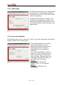
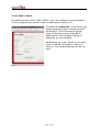
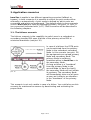
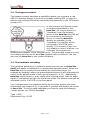
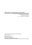
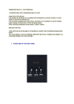
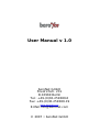
User Manual v 1.0
beroNet GmbH
Friedrichstr. 231
D-10969 Berlin
Tel.: +49-(0)30-259389-0
Fax: +49-(0)30-259389-19
www.beronet.com
E-Mail:[email protected]
© 2007 • beroNet GmbH
All trade marks used in this document are the property of the
owner.
Last update:
01.02.2007
Editor:
beroNet GmbH
Friedrichstraße 231
10969 Berlin
Infoline:
Fax:
E-Mail:
Internet:
+49-(0)30-259389-0
+49-(0)30-259389-19
[email protected]
www.beronet.com
1. First Steps
4
Page 2 of 20
1.1.
Delivery content
4
1.2.
Safety information
4
1.3.
Access
4
1.4.
Initiation
4
2. Configuration
5
2.1.
5
Detection or IP-address setting
2.1.1.
Automatic configuration via DHCP
5
2.1.2.
Standard IP-address in factory status
5
2.1.3.
Detection of the equipment with the bntools
5
2.2.
The web interface
6
2.2.1.
Relais mode
6
2.2.2.
Operating scenario
7
2.2.3.
Powerports
7
2.2.4.
Watchdog
8
2.2.5.
bero*fos defaults
8
2.2.6.
Watchdog config
9
2.2.7.
Network config
9
2.2.8.
Mail/Allerts
10
3. Application scenarios
11
3.1.
The failover scenario
11
3.2.
The bypass scenario
12
3.3.
The hardware watchdog
12
4. The bntools
13
4.1.
General information about bntools
13
4.2.
Installation of bntools
13
4.2.1.
Installation of bntools in Windows
13
4.2.2.
Installation of bntools in Linux
13
4.3.
Detection of bero*fos in your network
14
4.4.
Setting network configurations
14
4.5.
Release of heartbeat
15
4.6.
Firmware upgrade
15
5. Attachments
16
5.1.
Reference of instructions bntools
16
5.2.
Syslog
17
Page 3 of 20
1. First steps
1.1. Delivery content
1x bero*fos device
1x power card
1.2. Safety information
The bero*fos has been developed as IT-equipment and should be used in
this field.
Make sure that the equipment you want to access does not excess the
maximum switching capacity. You can find the maximum switching
capacity under “Technical data”.
1.3. Connection
Remove the bero*fos out of the package and assemble it into the rack.
The assembly brackets and the bero*fos are matched for 19’’ racks.
You can also use the device without a rack. Please make sure that there is
a fixation for the bero*fos at its destination. The delivered power card
assures the current supply. Connect bero*fos by using of a standard
network cable with the LAN-port of your network.
1.4. Initiation
Switching-on bero*fos occurs by pressing the on/off button on the front of
the device. If everything is connected correctly the device will start up. In
the regular operating status you will hear a small BEEP and the ports A-D
will blink green and red.
Page 4 of 20
2. Configuration
The bero*fos is accessible over several ways. One way is over the web
interface. The other way is over our software Library bntools. The library
bntools are freely downloadable from our website:
http://www.beroNet.com/downloads/berofos More information about bntools see chapter 4ff.
A valid IP-address from your network is essential for configuration of
bero*fos. The following chapter will show you several ways to do this.
2.1. Detection or setting the IP-address manually
There are different options to detect the IP-address of bero*fos in your
network:
•
automatic configuration via DHCP
•
standard IP-address in factory status
•
detection of the equipment with the bntools
2.1.1. Automatic configuration via DHCP
In factory default the bero*fos is in DHCP mode. That means it searches
for a DHCP-server in the network and requests an IP-address. Please check
the logs of your DHCP-Server to see which IP-address has been assigned
from your DHCP-server for the bero*fos.
2.1.2. Standard IP-address (factory default)
In factory default the bero*fos is in DHCP mode. If there is no DHCPserver in your network the bero*fos will keep its default IP-address
192.168.0.2 with the subnet 255.255.255.0.
2.1.3. Detection of the equipment with the bntools
For detection of bero*fos in your network you will need the command line
program bntools. More information about installing und using of bntools
see chapter 4.4
Page 5 of 20
2.2. The web interface
You can access the web interface of the bero*fos by entering the IPaddress in the address bar of your web browser.
After that you will see the main page of
bero*fos (pict. 1).
In the upper field you can see the
current state of the relays as well as
the operating scenario. In our case the
operating scenario is set to fallback,
the relay state of ports A-B are
“connected” and the ports A-D are
“disconnected”.
In the section “Control/Status” you can
set the relay state, change the
operating scenario, set the state of the
power ports and change the watchdog
parameters.
pict. 1
In the section “Configuration” you can set the start-up parameters, the
watchdog parameters as well as the configuration of the network and main
settings.
2.2.1. Relay mode
In the section “Relay-Mode” (pict. 2) you can check and set the current
relay state as well as in the operating scenario.
pict. 2
In pict.2 you can see that the current
operating scenario is fallback. The
relays of port A-D are “connected” and
the ports A-B are “disconnected”. This
working state is displayed through
LED’s on the front of the device. In this
case all 4 LED's of port A and all 4 of
port D should glow green (connected)
and the LED's of port B and C should
glow red (disconnected).
Using the button “switch: A-D” the relay
state would change to “A-B connected
and A-D disconnected”.
Page 6 of 20
2.2.2. Operating scenario
Using „Scenario Config“you can
configure the operating scenario of
bero*fos. You can choose between the
fallback or bypass scenario. More
information about these scenarios see
chapter 3.
pict. 3
2.2.3. Powerports
By selecting the menu item
“Powerports” the power ports on the
backside of bero*fos will be switched
on/off.
In this case power port 1 is switched off;
power port 2 is switched on. You can
change their state using “on” or “off”
buttons. The working state of the power
ports will be displayed through green or
red LED’s on the front of the device.
pict. 4
Page 7 of 20
2.2.4. Watchdog
By selecting the menu item “Watchdog”
you activate or deactivate watchdog.
Furthermore you can check the current
state of watchdog.
By selecting the button “refresh” you
can see the remaining seconds until
watchdog is generating a failover. This
is very practical to check and test your
applications.
pict. 5
2.2.5. bero*fos defaults
By selecting menu item “bero*fos” (pict.6) you can determine the default
states of bero*fos at starting-up.
pict. 6
The working states of the relay
and of the power ports are
adjustable. Please note that the
working state of the relay is
depending on the operating
scenario.
It is recommendable to set the
relays on mode 1 because this is
also the state when the device
has no power. Depending of the
operating scenario the state of
the relays are as follows:
Mode 0:
Failover: A-B connected
Bypass: A-B, C-D connected
Mode 1:
Failover and Bypass A-D
connected
Page 8 of 20
2.2.6. Watchdog config
By selecting menu item “Watchdog Config” the watchdog parameters are
accessible (see pict.7)
The default state of watchdog is
adjustable at starting-up. These adjust
if watchdog should be activated or
deactivated after switching-on the
device.
pict. 7
Using the “Watchdog Intervall” you
can set the time period in seconds
which the watchdog is waiting before
it generates a failover in case of
receiving no heartbeat. The point
Audio Failover can additionally
generate an Audio signal in case of a
failover. A failover is also signalled via
a red LED on the front of the device.
2.2.7. Network Config
You can set the following parameters:
•
DHCP: If it is activated an IPaddress will be requested after
every switch-on.
•
Hostname: Sets the network
name.
•
IP-Configuration: You can change
IP-address, net mask, gateway
and DNS, if you don’t want to
request these configurations
automatically via DHCP.
•
HTTP port: You can set the port
of the internal web server. Any
value between 1 and 65534
(standard: port 80) is valid.
pict. 8
This port number would be
added to the address of
bero*fos using a colon, e.g.
http://192.168.0.2:1720/
•
Page 9 of 20
Password: If requested you can
activate a password access. In
this case you have to set an
admin-password (max. 15
marks).
Page 10 of 20
2.2.8. Mail / Alerts
By selecting menu item “Mail / Alerts” you can configure the parameters
of the Syslog-server and the mail-configurations (see pict.9).
If needed the bero*fos could inform you
about important state changes as well
as failovers. This information will be
send via Syslog to your selected IPaddress/Port. See Chapter Syslog in
appendix for more details.
Additionally you can choose if you want
to be informed via email in case of a
failover. The proper settings can be set
here.
pict. 9
Page 11 of 20
3. Application scenarios
bero*fos is usable in two different operating scenarios (fallback or
bypass). In both scenarios it is possible to switch the port modes either
manually or automatically. A port mode is defined by which ports are
connected and which are unplugged. The default mode in every scenario
(even if bero*fos fails itself by unplugging power), the ports „A“ and „D“
are connected (indicated with „A-D“). Both scenarios will be described in
the following chapters.
3.1. The failover scenario
The failover scenario is the capability to switch over to a redundant or
secondary standby PBX upon a failure of the primary active PBX to
minimize downtimes (see pict.10).
pict. 10
In case of a failover the PSTN ports
can be switched from the primary
Node to the redundant secondary
Node. In this scenario (see pict. 10)
the equipments are named primary
Node and secondary Node. The
primary Node is sending a
heartbeat either to bero*fos or to
the secondary Node.
As long as there is a "heartbeat"
from the primary Node to the
second Node (or bero*fos itself),
the secondary Node will not initiate
its systems. The secondary Node
will immediately take over all ports
as soon as it detects an alteration
in the "heartbeat" of the primary
Node.
This scenario is not only usable in case of a failure. You could also use this
scenario for maintenance reasons by deactivating and activating the
proper Node.
Page 12 of 20
3.2. The bypass scenario
The bypass scenario describes a possibility where you can place a new
PBX (i.e. Asterisk-Server) in front of an already existing PBX. In case of a
failover the existing PBX will be connected transparently to the PSTN ports
(see pict.11).
In this scenario the Asterisk server
is sending a Heartbeat to the
bero*fos. As long as there is a
"heartbeat" from the Asterisk
server to the bero*fos the PBX will
be connected to the Asteriskserver. In case the bero*fos
detects an alteration in the
"heartbeat" the old PBX will be
connected to the PSTN ports
directly. This scenario is also not
only usable in case of a failure. You
could use this scenario for
pict. 11
maintenance reasons of the Asterisk server. The described scenario is only
an example how to use the bero*fos together with an Asterisk. You can
also use the bero*fos in any similar situations.
3.3. The hardware watchdog
The hardware watchdog is a software daemon running on the bero*fos
itself and awaits a heartbeat in a configurable timeout period. When the
bero*fos will not receive this heartbeat by an external server (for
example by Asterisk) within the preconfigured timeout it will automatically
switch to the default mode of the running scenario („A-D“). Additionally
bero*fos could send an e-mail, could send a Syslog event, start an audio
signal (if configured) and go into the failure mode. The failure mode will be
indicated via the „Fail“LED on the front panel.
You could generate the heartbeat either by using the bntools (for more
information see chapter 4.5.) or generate it yourself and send it via socket
to bero*fos. To send a valid heartbeat you have to send the following
“magic packet” per UDP to bero*fos:
Type = UDP
Destination Port: 50123
Page 13 of 20
4. bntools
The command line program bntools includes tools to control bero*fos as
well as an Asterisk resource module res_bnfos. bntools is downloadable
from our website:
http://www.beronet.com .
4.1. General information about bntools
As aforementioned you can use the bntools to control bero*fos. Using
bntools you can set and change any parameter of bero*fos like kicking
the watchdog or changing network parameters.
Before describing bntools we want to take the chance to show you some
hints which makes working with bero*fos easier. bero*fos has two
operating modes – the flash mode and the operational mode. Using the
device in flash mode you can reset bero*fos or update the firmware. Using
the device in the operational mode you can
start the watchdog or kick it for instance. Please note that some
commands are only available during the flash mode and other commands
only during the operational mode.
To control bero*fos with bntools you will always need the IP-address of
the device as well as the MAC-address. With the scan command you can
detect bero*fos on the network. With the parameter -x you can store the
result automatically in a file.
bnfos –scan –x will detect all bero*fos units in your network and additionally
save the results under “/etc/bnfos.conf”.
For all further instructions you can use the values stored in the file so you
don't have to type them again and again. To do this use the parameter -f
like in the following example
bnfos - -show –f fos1 will use the parameters of the first detected device
which have been stored with bnfos -scan -x
More information can be found typing bnfos --help or in the reference
section of instructions.
Page 14 of 20
4.2. Installation of bntools
4.2.1. Installation of bntools using Windows
Please download the software package under
http://www.beronet.com/downloads/docs/berofos/tools/windows/bnfos.rar
and unpack the archive in your target directory. Start the program using
the command line.
4.2.2. Installation of bntools using LINUX
Please download the tar.gz archive under
„http://www.beronet.com/downloads/docs/berofos/tools/linux/bntools.tar.g
z“
and compile it with make and make install. If you use bero*fos with an
Asterisk you will be able to install the resource module with make
res_bnfos.
4.3. Detection of bero*fos in your network
You have the possibility to detect any bero*fos in your network using
bntools even if the device has no IP-address. To do this you have to type
bnfos –scan.
pict. 14
If your bero*fos is correctly installed in your network you will get similar
results as shown in picture 14. Please notice that bero*fos can only be
detected over Ethernet. bero*fos can not be detected in WLAN
environments and networks that are currently routed.
Page 15 of 20
4.4. Setting network configurations
For setting the network parameters bring the device in the flash mode. For
this press the black key (right side of the PW LED’s) while switching on the
bero*fos. If the device is in flash mode the red LED’s of port D will blink.
Detect the equipment with bnfos –scan –x in your network and set the
network configuration as follows:
„bnfos –netconf –f fos1 –i 172.20.23.23 –n 255.255.0.0 –g 172.20.0.1 –d 0“
As alternative without the –f option.
„bnfos –netconf –m 00:19:32:00:00:58 –i 172.20.23.23 –n 255.255.0.0 –g
172.20.0.1 –d 0“
pict. 15
The new network parameters will be activated after a restart of the device
(see pict.15).
4.5. Kick the heartbeat
With the parameter–kick in the bntools you can send a heartbeat to the
bero*fos:
bnfos –kick –m 00:19:32:00:00:58
With the parameters –c –b –w 5 you can periodically send a Heartbeat
every 5 sec (-w 5) to the bero*fos while the bntools starts as daemon (-c)
in the background (-b).
“bnfos –kick –f fos1 -c -b-w 5”
More information about this see reference of instructions.
Page 16 of 20
Page 17 of 20
4.6. Firmware upgrade
Before making a firmware upgrade set the device into the flash mode. Use
the following command in bntools to update the firmware:
“bnfos –flash firmwarexy.bin –f fos1”.
Once this process is finished and bero*fos has been restarted you could
use the device with the new firmware. For more information just download
the “deviceupgrade.pdf” in the download section of our website
www.beronet.com.
Page 18 of 20
5. Attachement
5.1. Reference of instructions bntools
Usage: bnfos <MODE> ...
operation modes:
--scan [-h <host>] [-c] [-w <time>] [-t <sec>] [-s] [-x] scan the network for devices
--netconf { -m <mac> [-h <host>] | -f <id> } [-i <ip>] [-n <netmask>] [-g <gateway>] [-e <phy>] [-d
<status>] [-a <status>] [-p <port>] [-t <sec>] [-s] configure network parameters (flash mode only)
--ping { -m <mac> [-h <host>] | -f <id> } [-c] [-w <time>] [-t <sec>] [-s] send ping request
--kick { -m <mac> [-h <host>] | -f <id> } [-c] [-b] [-w <time>] [-t <sec>] [-s] kick watchdog timer
--reset { -m <mac> [-h <host>] | -f <id> } [-s] reset to default values (also deletes firmware)
--flash <file> { -m <mac> -h <host> | -f <id> } [-t <sec>] [-s] upload firmware (flash mode only)
--set <key>=<value> { -h <host> | -f <id> } [-p <port>] [-u <usrpwd>] [-t <sec>] [-s] set configuration
value
--get <key> { -h <host> | -f <id> } [-p <port>] [-u <usrpwd>] [-c] [-w <time>] [-t <sec>] [-s] show single
configuration or status value
--show { -h <host> | -f <id> } [-p <port>] [-u <usrpwd>] [-c] [-w <time>] [-t <sec>] [-s] shows configuration
and status
arguments:
-m <mac>
mac address of the device (notation: XX:XX:XX:XX:XX:XX)
-h <host>
hostname or ip address of the device (default: 255.255.255.255)
-p <port>
http port (default: 80)
-u <usrpwd>
authentification data (notation: <username>:<password>)
-c
continuous operation
-b
fork to background (implies -s)
-w <time>
wait 'time' seconds between continuous operations (default: 2)
-t <sec>
timeout in seconds (default: 3)
-s
enable syslog output
-x
write scan results to /etc/bnfos.conf
-f <id>
load mac and/or ip address from /etc/bnfos.conf
-i <ip>
configure ip address (default: 0.0.0.0)
-n <netmask>
configure netmask address
-g <gateway>
configure gateway address (default: 0.0.0.0)
-e <phy>
configure ethernet phy configuration (values: 0=auto; 1=10mbit; 2=100mbit; default:
0)
-d <status>
configure enable dhcp (1=on; 0=off; default: 1)
-a <status>
configure enable http auth (1=on; 0=off; default: 0)
-p <port>
configure http port (default: 80)
valid '--set' <key>=<value> pairs / '--get' keys:
scenario={0|1}
scenario (0=fallback; 1=bypass)
mode={0|1}
relais mode (0=A--D; 1=A--B or A--B,C--D)
modedef={0|1}
default relais mode (0=A--D; 1=A--B or A--B,C--D)
power1={0|1}
state of powerport 1 (0=off; 1=on)
power1def={0|1}
default state of powerport 1 (0=off; 1=on)
Page 19 of 20
power2={0|1}
state of powerport 2 (0=off; 1=on)
power2def={0|1}
default state of powerport 2 (0=off; 1=on)
hostname=<dn>
device hostname
address=<ip>
ip address
netmask=<nm>
netmask address
gateway=<gw>
gateway address
dns=<dns>
dns server address
dhcp={0|1}
query dhcp server (0=off; 1=on)
port={1..65535}
http listen port
pwd={0|1}
http password protection (0=off; 1=on)
apwd=<apwd>
admin password (only --set)
smtpserv=<mhost>
smtp server
smtpfrom=<mfrom>
smtp sender address
smtpto=<mto>
smtp destination address
smtptest=<XXXXX>
trigger testmail (only --set)
syslog={0|1}
syslog logging (0=off; 1=on)
slgip=<loghost>
syslog server ip
slgpt={1..65535}
syslog server port
wdog={0|1}
watchdog enable (0=off; 1=on)
wdogdef={0|1}
default watchdog enable (0=off; 1=on)
wdogstate=<wstate>
watchdog state (0=off; 1=on; 2=failure)
wdogitime={1..65535} watchdog intervall time
wdogaudio={0|1}
watchdog audio alarm (0=off; 1=on)
wdogmail={0|1}
watchdog alarm mails (0=off; 1=on)
wdogrtime=<wretv>
watchdog remaining time to failure
5.2. Syslog Output
Powerup:
berofos:00: Powerup
Relay States:
berofos:10: Relay Mode changed: A-D
berofos:11: Relay Mode changed: A-B
berofos:12: Relay Mode changed: A-B,C-D
Szenarios:
berofos:20: Szenario changed: Fallback
berofos:21: Szenario changed: Bypass
PowerPorts
berofos:30: PW1 Mode changed: on
berofos:31: PW1 Mode changed: off
berofos:32: PW2 Mode changed: on
berofos:33: PW2 Mode changed: off
Watchdog:
berofos:40: Wdog swithed: on
berofos:41: Wdog swithed: off
berofos:42: Wdog swithed: Failover (timeout)
berofos:43: Wdog swithed: Failover (sticky)
Page 20 of 20