1
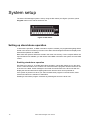
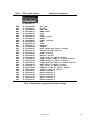
Alien LED Downlight™
user manual
Dimensions
All dimensions are in millimeters
Driver unit
Transformer
268
48
32
230
123
50
105
117
Luminaire
Ø85
68.5
Ø63
Ø51
5.2
©2008 Martin Professional A/S. Information subject to change without notice. Martin Professional A/S and all affiliated companies
disclaim liability for any injury, damage, direct or indirect loss, consequential or economic loss or any other loss occasioned by the
use of, inability to use or reliance on the information contained in this manual. The Martin logo, the Martin name and all other
trademarks in this document pertaining to services or products by Martin Professional A/S or its affiliates and subsidiaries are
trademarks owned or licensed by Martin Professional A/S or its affiliates or subsidiaries. The use of certain patents in Martin Alien
LED Downlight products is licensed by Color Kinetics, Inc. (see details printed on product).
P/N 35000215, Rev. D
Safety Information
WARNING!
Read the safety precautions in this section before
installing, powering, operating or servicing this
product.
The following symbols are used to identify important safety information on the product and in this
manual:
Warning!
Warning!
Safety hazard.
Hazardous
Risk of severe voltage. Risk of
injury or death. lethal or severe
electric shock.
Warning!
Fire hazard.
Warning!
Refer to user
manual.
Warning! This product is for professional use only. It is not for household use. This product
presents risks of injury or death due to fire hazards, electric shock and falls. Read this manual
before installing, powering or servicing the fixture, follow the safety precautions listed below and
observe all warnings in this manual and printed on the fixture. Install and operate the fixture only
as described in this manual and in accordance with local laws and regulations. Refer any
operation not described in this manual to a qualified technician.
If you have questions about how to operate the fixture safely, please contact your Martin supplier
or call the Martin 24-hour service hotline on +45 8740 0000, or in the USA on 1-888-tech-180.
PROTECTION FROM ELECTRIC SHOCK
• Shut down power to the entire installation at the main power distribution board and lock out
power (by removing the power distribution fuse for example) before carrying out any installation
or maintenance work.
• Disconnect the devices from AC power before removing or installing any cover or part and
when not in use for an extended period.
• Connect the driver unit electrically to ground (earth).
• Do not connect the driver unit to an AC power source outside the voltage ranges and frequency
specified in this manual
• Before applying power, check that the voltage selector switch on the driver unit is set to match
the local power source voltage.
• Use only a source of AC power that complies with local building and electrical codes and has
both overload and ground-fault (earth-fault) protection.
• Before using the devices, check that all power distribution equipment and cables are in perfect
condition, are rated for the current requirements of all connected devices and are of suitable
type for the location.
• Isolate the devices from power immediately if any cable or other component is damaged,
cracked or deformed. Do not reapply power until repairs have been completed.
• Do not expose any part of a driver unit or transformer to water or any other fluid. Install these
devices in dry locations only.
• Luminaires are IP67-rated but do not install them in a location where they may become
immersed in water.
• Refer any service operation not described in this manual to an authorized Martin Service
partner.
PROTECTION FROM BURNS AND FIRE
• Do not operate the devices if the ambient temperature (Ta) exceeds 40° C (104° F).
• Provide free airflow and a minimum clearance of 50 mm (2.0 in.) around the devices and allow
sufficient ventilation to ensure that the ambient temperature around driver units and
transformers does not exceed 40° C (104° F) and the ambient temperature around luminaires
does not exceed 45° C (113° F).
• Allow the devices to cool for 20 minutes before servicing.
• Do not illuminate surfaces less than 0.1 m (4 in.) from the front surface of the luminaire.
• Keep highly flammable materials well away from the devices.
• Do not modify the devices in any way not described in this manual or install other than genuine
Martin parts. Do not stick filters, masks or other materials directly onto LEDs. Use only Martin
approved accessories to mask or modify the light beam.
• Do not attempt to bypass thermostatic switches or fuses. Replace defective fuses with ones of
the specified type and rating only.
• Provide a minimum center-to-center distance of 100 mm (4.0 in.) between Alien LED Downlight
luminaires.
PROTECTION FROM INJURY
• Do not look at LEDs with magnifiers or similar optical instruments that may concentrate the
light output.
• The edges of devices and wing clips may cause cuts if not handled carefully. Protect yourself
with gloves during installation and service.
• Ensure that all external covers, components and installation fittings are securely fastened.
• Block access below the work area and work from a stable platform whenever installing,
servicing or moving the fixture.
• Ensure that all supporting structures, surfaces, fasteners and lifting equipment can bear the
weight of all the devices they are intended to support plus an adequate safety margin, and that
they conform to local building and safety regulations.
• Use a sufficient number of fasteners with sufficient corrosion resistance, dimensions and
strength to mount devices safely. Any nuts used must be self-locking. Install locking washers
under the heads of fasteners.
Disposing of this product
Martin™ products are supplied in compliance with Directive 2002/96/EC of the
European Parliament and of the Council of the European Union on WEEE (Waste
Electrical and Electronic Equipment), as amended by Directive 2003/108/EC, where
applicable.
Help preserve the environment! Ensure that this product is recycled at the end of its
life. Your supplier can give details of local arrangements for the disposal of Martin
products.
Contents
Dimensions . . . . . . . . . . . . . . . . . . . . . . . . . . . . . . . . . . . . . . . . . . . . . . . . . . . . . . . . . . . . . . . . . . . . . . . . 2
Safety Information . . . . . . . . . . . . . . . . . . . . . . . . . . . . . . . . . . . . . . . . . . . . . . . . . . . . . . . . . . . . . . . . . . 3
Introduction . . . . . . . . . . . . . . . . . . . . . . . . . . . . . . . . . . . . . . . . . . . . . . . . . . . . . . . . . . . . . . . . . . . . . . . . 7
Unpacking . . . . . . . . . . . . . . . . . . . . . . . . . . . . . . . . . . . . . . . . . . . . . . . . . . . . . . . . . . . . . . . . . . . . . . . . 7
Using for the first time . . . . . . . . . . . . . . . . . . . . . . . . . . . . . . . . . . . . . . . . . . . . . . . . . . . . . . . . . . . . . . . 7
Physical installation . . . . . . . . . . . . . . . . . . . . . . . . . . . . . . . . . . . . . . . . . . . . . . . . . . . . . . . . . . . . . . . . 8
Location and orientation . . . . . . . . . . . . . . . . . . . . . . . . . . . . . . . . . . . . . . . . . . . . . . . . . . . . . . . . . . . . . 8
Mounting and fastening luminaires . . . . . . . . . . . . . . . . . . . . . . . . . . . . . . . . . . . . . . . . . . . . . . . . . . . . . 8
Mounting and fastening driver units and transformers. . . . . . . . . . . . . . . . . . . . . . . . . . . . . . . . . . . . . . . 9
System overview . . . . . . . . . . . . . . . . . . . . . . . . . . . . . . . . . . . . . . . . . . . . . . . . . . . . . . . . . . . . . . . . . . 10
Maximum cable lengths . . . . . . . . . . . . . . . . . . . . . . . . . . . . . . . . . . . . . . . . . . . . . . . . . . . . . . . . . . . . . 11
AC power . . . . . . . . . . . . . . . . . . . . . . . . . . . . . . . . . . . . . . . . . . . . . . . . . . . . . . . . . . . . . . . . . . . . . . . . . 12
Setting to the local power voltage . . . . . . . . . . . . . . . . . . . . . . . . . . . . . . . . . . . . . . . . . . . . . . . . . . . . . 12
Connecting to power . . . . . . . . . . . . . . . . . . . . . . . . . . . . . . . . . . . . . . . . . . . . . . . . . . . . . . . . . . . . . . . 12
Power source quality . . . . . . . . . . . . . . . . . . . . . . . . . . . . . . . . . . . . . . . . . . . . . . . . . . . . . . . . . . . . . . . 13
Connecting heads . . . . . . . . . . . . . . . . . . . . . . . . . . . . . . . . . . . . . . . . . . . . . . . . . . . . . . . . . . . . . . . . . 14
Control data link . . . . . . . . . . . . . . . . . . . . . . . . . . . . . . . . . . . . . . . . . . . . . . . . . . . . . . . . . . . . . . . . . . . 15
Connecting the data link . . . . . . . . . . . . . . . . . . . . . . . . . . . . . . . . . . . . . . . . . . . . . . . . . . . . . . . . . . . . 16
System setup . . . . . . . . . . . . . . . . . . . . . . . . . . . . . . . . . . . . . . . . . . . . . . . . . . . . . . . . . . . . . . . . . . . . . 18
Setting up stand-alone operation. . . . . . . . . . . . . . . . . . . . . . . . . . . . . . . . . . . . . . . . . . . . . . . . . . . . . . 18
Setting up DMX operation . . . . . . . . . . . . . . . . . . . . . . . . . . . . . . . . . . . . . . . . . . . . . . . . . . . . . . . . . . . 20
Operation . . . . . . . . . . . . . . . . . . . . . . . . . . . . . . . . . . . . . . . . . . . . . . . . . . . . . . . . . . . . . . . . . . . . . . . . . 23
Ambient temperatures . . . . . . . . . . . . . . . . . . . . . . . . . . . . . . . . . . . . . . . . . . . . . . . . . . . . . . . . . . . . . .
Status LEDs on the driver unit . . . . . . . . . . . . . . . . . . . . . . . . . . . . . . . . . . . . . . . . . . . . . . . . . . . . . . . .
DMX-controlled operation . . . . . . . . . . . . . . . . . . . . . . . . . . . . . . . . . . . . . . . . . . . . . . . . . . . . . . . . . . .
Stand-alone operation . . . . . . . . . . . . . . . . . . . . . . . . . . . . . . . . . . . . . . . . . . . . . . . . . . . . . . . . . . . . . .
23
23
23
23
Service and maintenance . . . . . . . . . . . . . . . . . . . . . . . . . . . . . . . . . . . . . . . . . . . . . . . . . . . . . . . . . . 24
Cleaning. . . . . . . . . . . . . . . . . . . . . . . . . . . . . . . . . . . . . . . . . . . . . . . . . . . . . . . . . . . . . . . . . . . . . . . . . 24
DMX protocol . . . . . . . . . . . . . . . . . . . . . . . . . . . . . . . . . . . . . . . . . . . . . . . . . . . . . . . . . . . . . . . . . . . . . 25
RGBW Mode . . . . . . . . . . . . . . . . . . . . . . . . . . . . . . . . . . . . . . . . . . . . . . . . . . . . . . . . . . . . . . . . . . . . . 25
HSI Mode. . . . . . . . . . . . . . . . . . . . . . . . . . . . . . . . . . . . . . . . . . . . . . . . . . . . . . . . . . . . . . . . . . . . . . . . 25
Troubleshooting . . . . . . . . . . . . . . . . . . . . . . . . . . . . . . . . . . . . . . . . . . . . . . . . . . . . . . . . . . . . . . . . . . 26
Specifications . . . . . . . . . . . . . . . . . . . . . . . . . . . . . . . . . . . . . . . . . . . . . . . . . . . . . . . . . . . . . . . . . . . . . 27
Notes
6
Alien LED Downlight user manual
Introduction
Thank you for selecting the Alien LED Downlight™, a compact LED-based color-changing
recessed spotlight system from Martin™. The system features:
• RGBW color mixing and HSI (hue, saturation, intensity) control options
• DMX-512A control or stand-alone operation
• Near unity power factor and ultra-high efficiency
• Switchable 100-120/208-240 V, 50/60 Hz operating range
• Optional trim rings (chrome, brass and white)
For the latest documentation, product specifications and other information about this and all
Martin Professional™ products, please visit the Martin website at http://www.martin.com
Comments or suggestions regarding this document may be e-mailed to [email protected] or
posted to:
Service Department
Martin Professional A/S
Olof Palmes Allé 18
DK-8200 Aarhus N
Denmark
Unpacking
The Alien LED Downlight standard model, high-power model and driver unit are supplied packed
separately. Labels on the luminaire or luminaire wiring identify standard and high-power
luminaires.
The following items are included with the Alien LED Downlight standard model, P/N 90353000:
• 2 x downlight luminaires with mounting hardware and stainless steel trim ring
• 1 x transformer with 100 mm patch cable and RJ-45 T-connector
The following items are included with the Alien LED Downlight high-power model, P/N 90353040:
• 1 x high-power downlight luminaire with mounting hardware and stainless steel trim ring
• 1 x transformer
The following items are included with the Alien LED Downlight driver, P/N 90734510:
• 1 x Alien LED Downlight driver unit
• 1 x 3-pin male XLR to male RJ-45 adapter
• This user manual
Using for the first time
Before applying power to the system:
• Review “Safety Information” on page 3.
• Check that the local AC power voltage is within the ranges listed on the fixture’s serial number
label and that the voltage selector switch on the driver unit is set to match the local AC power
voltage.
Introduction
7
Physical installation
Warning! Read "Safety Information" on page 3 before installing the Alien LED Downlight.
The safety and suitability of installation location, anchoring method, mounting hardware
and electrical installation is the responsibility of the installer. All local safety regulations
and legal requirements must be observed when installing and connecting the Alien LED
Downlight. Installation must be carried out by qualified professionals only.
The ambient temperature around driver units and transformers must not exceed 40° C
(104° F). The ambient temperature around luminaires must not exceed 45° C (113° F).
Provide ventilation as necessary to ensure these levels are not exceeded. Leave at least
50 mm (2.0 in.) of free space and allow airflow around driver units, transformers and
luminaires.
Contact your Martin™ supplier for assistance if you have any questions about how to
install this product safely.
Location and orientation
Warning! Install luminaires, transformers and driver units at least 50 mm (2 in.) away from
thermal insulation material and well away from highly flammable materials.
Downlight luminaires are designed to be installed in a ceiling or wall recess with a ceiling or wall
thickness of 5 - 22 mm (0.2 - 0.85 in.).
Allow for service access to driver units and transformers.
Important! When installing luminaires in a row or group, ensure homogenous light
distribution by orienting them all in the same direction (i.e. with the luminaire wiring
facing in the same direction on all luminaires).
Mounting and fastening luminaires
Luminaires can be fixed into position by two methods:
• A tank nut on the 2-inch BSP thread on the luminaire housing, for which a 63 mm (2.5 in.)
diameter cutout in the ceiling or wall is required. Access to the ceiling or wall recess is required
in order to tighten the tank nut. The tank nut mount is recommended in indoor and outdoor
installations.
• A plasterboard clip system, for which a 70 mm (2.8 in.) diameter cutout in the ceiling or wall is
required. Access to the ceiling or wall recess is not required in order to fasten the luminaire, as
the luminaire is pushed into position from outside the recess and the wing clips spring open to
hold the luminaire in position. The plasterboard clip system is recommended in indoor
installations only.
In both methods, high-pressure nitrile O-rings ensure a gas and vapor seal when the luminaire is
correctly installed.
Tank nut mounting
1. Use a hole saw mounted on a power drill to drill a 63 mm (2.5 in.) diameter circular hole in the
mounting surface.
2. Push the luminaire up into the hole, install a suitable washer and nut on the 2-inch BSP thread
in the luminaire housing, and tighten the nut to secure the luminaire.
8
Alien LED Downlight user manual
Plasterboard clip mounting
1. See Figure 1. Check that the trim ring is fully fastened onto the luminaire and that the first of
the supplied nitrile O-rings is located in the recess in the trim ring.
2. Clip the plasterboard mounting collar supplied with the fixture over the luminaire housing and
place the second nitrile O-ring (arrowed in Figure 1) over the collar so that the collar is
sandwiched between two O-rings.
3. Use a hole saw mounted on a power drill to drill a 70 mm (2.8 in.) diameter circular hole in the
mounting surface.
4. Pass the luminaire cable through the mounting hole and make any necessary connections.
5. Pressing the wing clips in towards the center, pass the luminaire housing through the
mounting hole. The wing clips will move outwards as they pass through the hole and into the
recess until they hold the luminaire firmly in position when fully inserted into the mounting
hole.
Wing clip
Wing clip
Mounting collar
Nitrile O-ring
Trim ring
Figure 1: Plasterboard mount collar
Mounting and fastening driver units and transformers
Fasten driver units and transformers securely to a flat surface in a location that is accessible for
service. Respect all local safety, fire and building regulations governing the installation of
electrical equipment in cavities or plenums. Allow free airflow and at least 50 mm (2 in.) of free
space around all devices. Allow sufficient ventilation to ensure that the ambient temperature will
not exceed 40° C (104° F).
When choosing a location for a driver unit, bear in mind that access to the DIP switch is required
if you need to change the DMX address or if you run luminaires in stand-alone operation and
need to change stand-alone programs.
Physical installation
9
System overview
Figure 2 gives a schematic overview of the Alien LED Downlight system layout.
DMX CONTROLLER
DMX control data
link (max. 500 m)
(e.g. Light Fox system)
DRIVER UNIT
Mains power input
100-120/208-240 V,
50/60 Hz
DMX in
RJ-45
IEC
DMX out
RJ-45
DMX output
available for other
driver units
Output available
for other
transformers
IEC
Max. 5 A
total on these
two outputs
combined
HEAD
1.5 m (max. 50 m)
Output available
for other
transformers
Transformer
with hard-wired IEC male
and female cable tails
RJ-45
EITHER
OR
0.1 m
RJ-45
T-Connector
1.5 m
1 x high-power
Alien LED
Downlight
1.5 m
1.5 m
2 x standard
power Alien
LED Downlights
Figure 2: Schematic cable and device layout
10
Alien LED Downlight user manual
The Alien LED Downlight™ system comprises:
1. A driver unit that relays signals from a DMX controller such as the Martin Light Fox™ to the
rest of the system via combined power/data cables. The driver unit also stores stand-alone
programs that it can run on the rest of the system without the need for a DMX controller.
2. A ‘head’ consisting of:
a. A transformer/receiver unit that accepts power/data signals from the driver unit and applies
variable intensity power to the different colored LEDs in the downlight or downlights
connected to it.
b. Either one high-power or two standard model IP67-rated downlight luminaires.
Maximum cable lengths
To ensure the quality of the data signal in the system, do not exceed the following maximum
permitted cable lengths:
Cable
Supplied length
Max. length
DMX data link from DMX controller to Driver Unit
Not supplied
500 m (1640 ft.)
Power/data link from Driver Unit to daisy-chained Driver Unit
Not supplied
50 m (164 ft.)
Power/data link from Driver Unit to transformer
1.5 m (4.9 ft.)
50 m (164 ft.)
total (i.e. to last
transformer on
link)
Power/data link from transformer to high-power luminaire
1.5 m (4.9 ft.)
1.5 m (4.9 ft.)
Power/data link from transformer to T-connector
Power/data link from T-connector to standard luminaires
100 mm (3.9 in.) 100 mm (3.9 in.)
1.5 m (4.9 ft.)
1.5 m (4.9 ft.)
Table 1: Maximum permitted cable lengths
System overview
11
AC power
Warning! Read “Safety Information” on page 3 before attempting to install this product.
Lock out power to the entire installation before working on cables and connections.
Electrical installation must be carried out by qualified professionals only.
For protection from dangerous electric shock, the driver unit must be grounded (earthed).
The AC power distribution system must be fitted with current overload and ground-fault
(earth-fault) circuit breakers as well as a means to isolate devices from power and lock out
power so that it cannot be reapplied during service.
The Alien LED Downlight driver unit can be connected to AC power at 100-120/208-240 V
nominal, 50/60 Hz. Do not connect to power at any other voltage or frequency.
Important! Do not connect any component in the Alien LED Downlight system to an
electrical dimmer system. Doing so can damage the electronics.
See Figure 2 on page 10 for a schematic diagram of cable layout. If you require help with
planning or installing an Alien LED Downlight system, please contact your Martin supplier for
assistance.
The Alien LED Downlight driver unit is protected by a 5 A slow-blow primary fuse (note that fuses
are not user-serviceable). See "Specifications" on page 27 for details of typical current drawn.
Power factor figures are given under "Specifications" on page 27. When operating on mains
power at 208 - 240 VAC, a power factor of 0.9 minimum is obtained when at least two heads are
installed.
Setting to the local power voltage
Before connecting the driver unit to power, check that the voltage selector switch on the side of
the driver unit is set to:
• 115 V if the local AC mains power voltage is 110-120 V, or
• 230 V if the local AC mains power voltage is 208-240 V.
The unit adapts automatically to 50 Hz or 60 Hz AC power.
Connecting to power
The Alien LED Downlight driver unit does not have a power on/off switch. Power is applied as
soon as the unit is connected to power.
The driver unit is supplied with a hard-wired UL-approved power cable with wires that are EU
color-coded (brown, blue, yellow/green) ready for connection to a single-phase 3-wire (live,
neutral, ground/earth) power distribution system.
12
Alien LED Downlight user manual
You may need to fit the power cable with a power plug that is suitable for your AC power outlets.
If so, install a grounding-type (earthed) plug that is rated 10 A minimum. Follow the plug
manufacturer’s instructions. Table 2 shows some possible pin identification schemes. If pins are
not clearly identified, or if you have any doubts about proper installation, consult a qualified
electrician.
Wire colors (USA)
Wire colors (EU)
Conductor
Symbol
Screw (USA)
black
brown
live
L
yellow or brass
white
blue
neutral
N
silver
green
yellow/green
ground (earth)
green
Table 2: Conductor identification
To connect to power:
1. Shut down power at source and ensure that it cannot be reapplied, even accidentally, by
removing a distribution circuit fuse for example.
2. Connect the conductors in the Alien LED Downlight driver unit power cable to the distribution
circuit as follows:
- Connect the yellow/green wire to ground (earth)
- Connect the blue wire to neutral
- Connect the brown wire to live.
3. Check that all installation work is completed and carry out appropriate tests and safety checks
before applying power.
Power source quality
The Alien LED Downlight system includes combined power and data cables. The system is
robust and can withstand normal mains power disturbances, but more serious interference on the
mains power circuit can cause individual downlights in multiple installations to lose step
temporarily, typically for a fraction of a second, until they recover and normal operation is
resumed. If momentary loss of step occurs, check the quality of your incoming mains power and
ensure that Alien LED Downlight cables are separated from any other cables that may be
carrying large amounts of noisy power.
AC power
13
Connecting heads
Whether you use DMX control or stand-alone operation, you need to connect heads so that
luminaires can draw power from transformers. See Figure 2 on page 10.
Warning! Ensure that the total current draw on both of the driver unit’s output sockets
added together does not exceed 5 A maximum.
Connect only Alien LED Downlight components to the Alien LED Downlight system, and
connect them only as shown in Figure 2 on page 10. Use only the cables supplied with the
system, and check that cables are in perfect condition before use.
Important! Before connecting two standard luminaires to a transformer, look carefully at
the RJ-45 T-connector used to branch the cable from the transformer. See Figure 2. The
RJ-45 sockets that must be used for input and output are clearly marked with arrows.
Observe these markings carefully, or you will damage the circuits in the T-connector.
Power cables that carry a strong current can affect the data signal in Alien LED Downlight
cables (see “Power source quality” on page 13). Route Alien LED Downlight system
cables as far as possible from potential sources of interference.
To connect heads:
1. Each transformer is hard-wired with a 1.5 m (4.9 ft.) power/data cable tail with an IEC male
connector. Connect the cable tail of the first transformer to the IEC female power/data output
socket of the first driver unit.
2. Continue linking transformers by connecting their cable tails to either a power/data output
socket on another transformer or a power/data output socket on a driver unit, up to a
maximum of 10 transformers in total per driver unit.
3. Each Alien LED Downlight luminaire is hard-wired
with a 1.5 meter (4.9 ft.) cable tail with an RJ-45
connector. Connect either:
a. two standard luminaires via the supplied 100
mm power patch cable and RJ-45 T-connector or
b. one high-power luminaire
OUT
to the RJ-45 output socket of each transformer.
See Figure 2. If you connect two standard luminaires
using a T-connector, use the connector with the
inward-pointing arrow for input from the transformer
and use the two outward-pointing arrows for output to
the luminaires.
14
Alien LED Downlight user manual
OUT
IN
Figure 2: RJ-45 T-connector
Control data link
The Alien LED Downlight system can be operated using a standard DMX dynamic lighting
control system if driver units are connected to a DMX controller via a control data link. Unlike the
combined power/data cables from driver units to the heads, the control data link from a DMX
controller to driver units carries data only.
Planning the data link
Before planning the data link, study Figure 2 on page 10 and the guidelines below. If you are
unsure about any aspect of installation, contact your Martin supplier for assistance.
Alien LED Downlight control principles
• Downlights are controlled by sending color and intensity commands from the DMX controller
over the data link to driver units. The driver units then relay these commands to the heads over
combined power/data cables.
• A head consists of one transformer that must be connected to either one high-power or two
standard downlight luminaires. Two standard luminaires connected to one transformer will
behave identically.
• A maximum of 10 heads may be connected to one driver unit. A driver unit can control up to 4
heads – or groups of heads – independently. This means for example that you can control one
head and 3 groups, each containing 3 heads, as four independent groups that show four
independent lighting effects. To give another example, you can also put all 10 heads into one
group and control them together, so that they all show the same lighting effects.
• One DMX universe has 512 DMX control channels available in the data signal. Channels 1 479 are available for use in an Alien LED Downlight system.
• The driver unit uses 4 DMX control channels to control a head:
- one channel for red, one for green, one for blue and one for white in RGBW mode, or
- one channel for hue, one for saturation, one for intensity and one redundant channel in HSI
mode.
• Since the driver unit can control up to 4 heads independently, it uses up to 16 DMX channels in
total (4 groups x 4 channels = 16).
Cable and link details
• Use RS-485 (also known as EIA-485) data cable for the data link. RS-485 cable has low
capacitance and a characteristic impedance of 85 to 150 Ohms. It is electrically shielded and
has at least 1 twisted pair of conductors. The minimum recommended wire size is 0.25 mm2
(24 AWG) for runs up to 300 meters (1000 ft.) and 0.32 mm2 (22 AWG) for runs up 500 meters
(1640 ft). CAT 5 network cable conforms to the RS-485 specification and is suitable for the data
link.
• The maximum permitted control data cable length before a control signal amplifier is required is
500 meters (1640 ft.).
• Devices that are connected to a controller via a data link must be ‘daisy-chained’, i.e. the data
cable must be connected in one single chain.
• Each chain may contain a maximum of 32 Alien LED Downlight driver units or similar devices.
• An optically isolated amplifier-splitter such as the Martin RS-485 Opto-Splitter (P/N 90758060)
must be used to:
- extend a control data link beyond 500 meters (1640 ft.), or
- branch the link into further single chains, each containing a maximum of 32 devices. The
Martin Opto-Splitter allows a link to be branched into four new chains, or
- extend the link if the maximum of 32 devices is reached.
• Each chain on the link must be terminated with a DMX termination plug in the output of the last
device in the chain.
Control data link
15
• Long parallel runs of AC power and control data cables may cause interference on the data link
and must be avoided. Even if not required by law, separate conduits must be used for power
and data cables.
Connecting the data link
Warning! Before working on cables and connections, isolate the entire installation from
power and lock out power so that it cannot be reapplied.
Connect either one high-power or two standard Alien LED Downlight luminaires to each
transformer.
Connect a maximum of ten transformers directly or indirectly to any one driver unit. The
total current draw for both output sockets on a driver unit added together must not exceed
5 A.
Read “Planning the data link” on page 15 before starting work and refer to Figure 2 on
page 10 while connecting the data link.
To connect the data link:
1. Isolate the installation from power and ensure that power cannot be reapplied.
2. Run data cable with suitable connectors from the DMX output socket on the DMX controller to
the RJ-45 DMX input socket on the first driver unit on the link.
3. If there are more driver units in the installation, continue linking them in a single chain,
connecting DMX output to DMX input sockets.
4. On the last driver unit in each chain on the link, insert an RJ-45 DMX termination plug
(available from Martin, P/N 91613082) in the DMX output socket.
5. After making all connections, set up the fixtures as described under “System setup” on
page 18 before applying power.
Connection pinouts
XLR connection
Many DMX lighting controllers have XLR output connectors. To connect these to the RJ-45
connectors in the Alien LED Downlight system, use an XLR to RJ-45 adapter, (included with
driver unit). If you need to rewire XLR connectors, pin numbers are normally marked on
connectors. Connectors must be wired using the standard XLR DMX pin-out:
• Pin 1: Cable shield
• Pin 2: DMX Data 1 - (cold)
• Pin 3: DMX Data 1 + (hot)
Pins 4 and 5 on 5-pin XLR connectors are available for Data 2 connections in DMX 512-A or
similar systems. They must be wired as follows:
• Pin 4: DMX Data 2 - (cold)
• Pin 5: DMX Data 2 + (hot)
Important! To avoid ground/earth loop interference, ensure that the DMX cable shield
does not come into contact with the shell or body of XLR connectors.
RJ-45 connection
RJ-45 connectors are easiest to manage if CAT 5 cable is used for the data link. RJ-45 cable
connector pins are numbered from the left looking at the face of the connector with the locking
clip on top (see Figure 3). Connectors must be wired according to the 568-B system using the
standard RJ-45 pin-out for DMX applications:
• Pin 1 (White/orange): DMX data hot (+)
• Pin 2 (Orange): DMX data cold (-)
16
Alien LED Downlight user manual
• Pins 7 (White/brown) and 8 (Brown): Common
Pins 3 and 6 are available for Data 2 connections in DMX
512-A or similar systems. They must be wired as follows:
• Pin 3 (White/green): Available for Data 2 hot (+)
• Pin 6 (Green): Available for Data 2 cold (-)
Pins 4 and 5 are not used in currently available lighting control
systems but can be wired as follows:
• Pin 4 (Blue)
• Pin 5 (White/blue)
Control data link
Pin 1
Pin 8
Figure 3: RJ-45 cable
connector pins
17
System setup
The Alien LED Downlight system is set up using the DIP switch (see Figure 4) and the yellow
Program button on the side of the driver unit.
Figure 4: DIP switch
Setting up stand-alone operation
In stand-alone operation, no DMX controller is required. Instead, pre-programmed lighting effects
stored in the driver unit memory are sent to the Alien LED Downlight luminaires for display when
stand-alone operation is enabled.
Both static and dynamic effects are stored in the driver unit memory. If more complex effects are
required than those available, you will need to add a DMX controller to the system and use DMX
control.
Enabling stand-alone operation
See Table 3 on page 19. To enable stand-alone operation, set the DIP switch pins on the driver
unit to a value from 480 to 511 to select one of the stand-alone programs stored in the driver unit
as shown in the table. All the downlights connected via transformers to the driver unit will now
display the selected stand-alone lighting effect each time the driver unit is powered on.
If the system is powered on when you select a stand-alone program on the DIP switch, allow
several seconds for the selection to take effect.
Enabling a stand-alone program overrides any DMX signal sent to the driver unit.
18
Alien LED Downlight user manual
Value
480
481
482
483
484
485
486
487
488
489
490
491
492
493
494
495
496
497
498
499
500
501
502
503
504
505
506
507
508
509
510
511
DIP switch setting
10 987654321
x 111100000
x 111100001
x 111100010
x 111100011
x 111100100
x 111100101
x 111100110
x 111100111
x 111101000
x 111101001
x 111101010
x 111101011
x 111101100
x 111101101
x 111101110
x 111101111
x 111110000
x 111110001
x 111110010
x 111110011
x 111110100
x 111110101
x 111110110
x 111110111
x 111111000
x 111111001
x 111111010
x 111111011
x 111111100
x 111111101
x 111111110
x 111111111
Stand-alone program
All off
W 100%
RGB 100%
RGBW 100%
Cyan
Blue
Light green
Green
Light yellow
Red
Pink
Magenta
Purple
Full spectrum color scroll
Yellow/orange scroll
Pinks scroll
Blues scroll
Whites scroll
Blue fade to white scroll
Light green fade to white scroll
Green fade to white scroll
Light yellow fade to white scroll
Red fade to white scroll
Pink fade to white scroll
Magenta fade to white scroll
Purple fade to white
White Warmth 1
White Warmth 2
White Warmth 3
White Warmth 4
White Warmth 5
White Warmth 6
Table 3: Stand-alone program DIP-switch settings
System setup
19
Setting up DMX operation
In DMX operation, commands from a DMX controller are sent to the driver units and then relayed
to the heads. The transformers in the heads translate the commands into dynamic lighting effects
by varying power to the LEDs in the luminaires.
A driver unit can relay commands to up to 4 different groups of heads independently. All heads
are supplied set to group 1 by default. If you want all heads to show the same lighting effects, go
straight to “Setting driver units’ DMX addresses” below.
If you want to show different lighting effects on different heads connected to the same driver unit,
continue Alien LED Downlight, you must first assign the heads into groups. All heads are
supplied assigned to group 1 by default. To assign them to a different group, you must first
initialize them and then set them to the new group number:
Configuring heads
1. Connect all the heads you want to include in a particular group to the driver unit. Disconnect
all the heads you do NOT want to include in that group.
2. Power the driver unit on.
3. Set all the driver unit’s DIP switch pins to OFF.
4. Move one DIP switch pin as follows:
- Move pin 2 to ON to set heads to group 2, or
- Move pin 3 to ON to set heads to group 3, or
- Move pin 4 to ON to set heads to group 4.
5. Hold the yellow Program button pressed in for 10 seconds until the luminaires blink green to
show that the heads connected to the driver unit are now assigned to the desired group.
6. If a transformer has previously been assigned to a group other than group 1, it will blink red
and refuse to accept the new group. If this happens, reset the transformer by setting all the
DIP switch pins on the driver unit to ON and holding the yellow ‘Enter’ button pressed in for 10
seconds. This initializes the transformer and sets it to the default group 1. You should now be
able to assign the heads to the new group.
7. Repeat this procedure until all heads are assigned to groups, then use the DIP switch pins to
set the driver unit’s DMX address as described below.
Setting driver units’ DMX addresses
When heads have been assigned to groups, you must set up the driver units and controller:
1. Set up the DMX controller so that 16 channels are allocated to each driver unit.
For example, if you have three driver units, allocate:
- Channels 1 - 16 to driver unit 1
- Channels 17 - 32 to driver unit 2
- Channels 33 - 48 to driver unit 3.
2. Set each driver unit to receive commands on the 16 channels reserved for it on the DMX
controller. You do this by setting the driver unit’s DMX address as a binary number on the
driver unit’s DIP switch. The DMX address is the first of the DMX channels used to receive
commands from the controller.
In our example, set DMX addresses as follows
- Set driver unit 1 to DMX address 1 (binary number 000000001 on the DIP switch)
- Set driver unit 2 to DMX address 17 (binary number 000010001 on the DIP switch)
- Set driver unit 3 to DMX address 33 (binary number 000100001 on the DIP switch)
3. See "DIP Switch settings table" on page 22 for a quick way of finding the binary numbers you
need to set on the DIP switch. Alternatively, use the Martin DIP Switch Calculator, available
20
Alien LED Downlight user manual
for use and download free of charge at http://www.martin.dk/service/dipswitchpopup.htm (see
Figure 5).
Figure 5: Martin™ DIP Switch Calculator
Setting the color control mode to RGBW or HSI
To set the Alien LED Downlight system to RGBW mode, set pin 10 of the DIP switch on the driver
unit to OFF. The 4 DMX channels used for each head connected to that driver unit will now
control the intensity of red, green, blue and white LEDs.
To set the Alien LED Downlight to HSI mode, set pin 10 of the DIP switch on the driver unit to ON.
The first 3 DMX channels used for each head connected to that driver unit will now control hue.
saturation and intensity. The fourth channel is redundant and has no function.
System setup
21
DIP Switch settings table
To use this table, first find the DMX address in the main block in the table. Then read the settings
for pins 1 - 5 to the left and read the settings for pins 6 - 9 above the address. “0” means OFF and
“1” means ON.
For example, to set the DMX address to 101, you need to set DIP switch pins 1, 3, 6 and 7 to ON,
as highlighted in the table.
DIP switch pins setting #9
0 = OFF
#8
1 = ON
#7
#6
#1 #2 #3 #4 #5
0
0
0
0
0
1
0
0
0
0
0
1
0
0
0
1
1
0
0
0
0
0
1
0
0
1
0
1
0
0
0
1
1
0
0
1
1
1
0
0
0
0
0
1
0
1
0
0
1
0
0
1
0
1
0
1
1
0
1
0
0
0
1
1
0
1
0
1
1
0
0
1
1
1
0
1
1
1
1
0
0
0
0
0
1
1
0
0
0
1
0
1
0
0
1
1
1
0
0
1
0
0
1
0
1
1
0
1
0
1
0
1
1
0
1
1
1
1
0
1
0
0
0
1
1
1
0
0
1
1
0
1
0
1
1
1
1
0
1
1
0
0
1
1
1
1
0
1
1
1
0
1
1
1
1
1
1
1
1
1
0
0
0
0
0
0
0
1
0
0
1
0
0
0
1
1
0
1
0
0
0
1
0
1
0
1
1
0
0
1
1
1
1
0
0
0
1
0
0
1
1
0
1
0
1
0
1
1
1
1
0
0
1
1
0
1
1
1
1
0
1
1
1
1
1
2
3
4
5
6
7
8
9
10
11
12
13
14
15
16
17
18
19
20
21
22
23
24
25
26
27
28
29
30
31
32
33
34
35
36
37
38
39
40
41
42
43
44
45
46
47
48
49
50
51
52
53
54
55
56
57
58
59
60
61
62
63
64
65
66
67
68
69
70
71
72
73
74
75
76
77
78
79
80
81
82
83
84
85
86
87
88
89
90
91
92
93
94
95
96
97
98
99
100
101
102
103
104
105
106
107
108
109
110
111
112
113
114
115
116
117
118
119
120
121
122
123
124
125
126
127
128
129
130
131
132
133
134
135
136
137
138
139
140
141
142
143
144
145
146
147
148
149
150
151
152
153
154
155
156
157
158
159
160
161
162
163
164
165
166
167
168
169
170
171
172
173
174
175
176
177
178
179
180
181
182
183
184
185
186
187
188
189
190
191
192
193
194
195
196
197
198
199
200
201
202
203
204
205
206
207
208
209
210
211
212
213
214
215
216
217
218
219
220
221
222
223
224
225
226
227
228
229
230
231
232
233
234
235
236
237
238
239
240
241
242
243
244
245
246
247
248
249
250
251
252
253
254
255
256
257
258
259
260
261
262
263
264
265
266
267
268
269
270
271
272
273
274
275
276
277
278
279
280
281
282
283
284
285
286
287
288
289
290
291
292
293
294
295
296
297
298
299
300
301
302
303
304
305
306
307
308
309
310
311
312
313
314
315
316
317
318
319
320
321
322
323
324
325
326
327
328
329
330
331
332
333
334
335
336
337
338
339
340
341
342
343
344
345
346
347
348
349
350
351
352
353
354
355
356
357
358
359
360
361
362
363
364
365
366
367
368
369
370
371
372
373
374
375
376
377
378
379
380
381
382
383
384
385
386
387
388
389
390
391
392
393
394
395
396
397
398
399
400
401
402
403
404
405
406
407
408
409
410
411
412
413
414
415
416
417
418
419
420
421
422
423
424
425
426
427
428
429
430
431
432
433
434
435
436
437
438
439
440
441
442
443
444
445
446
447
448
449
450
451
452
453
454
455
456
457
458
459
460
461
462
463
464
465
466
467
468
469
470
471
472
473
474
475
476
477
478
479
480
481
482
483
484
485
486
487
488
489
490
491
492
493
494
495
496
497
498
499
500
501
502
503
504
505
506
507
508
509
510
511
Table 4: DMX address DIP switch settings
Note that:
• DIP switch pin 10 is reserved for setting driver units to RGBW or HSI modes.
• DMX addresses from 480 and upwards are not available because the DIP switch settings that
correspond to these addresses are reserved for setting stand-alone operation.
22
Alien LED Downlight user manual
Operation
Ambient temperatures
Devices can be operated within the following temperature ranges only:
• Alien LED driver units can be operated at ambient temperatures from 5° C (41° F) to 40° C
(104° F).
• Alien LED Downlight transformers can be operated at ambient temperatures from 0° C (32° F)
to 40° C (104° F).
• Alien LED Downlight luminaires can be operated at ambient temperatures from -25° C (-13° F)
to 45° C (113° F).
Status LEDs on the driver unit
Colored LEDs on the driver unit indicate current system status:
• Green = mains power on
• Yellow = valid DMX signal is present at DMX input
• Red = driver unit is in program mode
DMX-controlled operation
When the Alien LED Downlight system is set up for DMX-controlled operation, faders on the
DMX controller are used to control color and intensity. The control method depends on which
color control mode the Alien LED Downlight system is set to (see “Setting the color control mode
to RGBW or HSI” on page 21):
In RGBW mode, four channels on the controller are used to control the intensity of red, green,
blue and white from 0% to 100%.
In HSI mode, three channels on the controller are used to control hue, saturation and intensity.
• Hue is controlled in the following order: Red → Orange → Amber → Yellow → Green → Cyan
→ Blue → Indigo → Violet → Magenta → Red.
• Saturation and Intensity can be varied from 0% to 100%.
When the Alien LED Driver Unit is receiving a valid DMX signal, the yellow DMX OK LED next to
the DIP switch on the Driver Unit lights.
Stand-alone operation
When the Alien LED Downlight system is set up for stand-alone operation, downlights begin
displaying their stand-alone scene as soon as power is applied to the driver.
Operation
23
Service and maintenance
Warning ! Read “Safety Information” on page 3 before carrying out service or maintenance
work on the Alien LED Downlight installation. Isolate the entire installation from power
and ensure that power cannot be reapplied before carrying out any work on the
installation.
Any service procedures not described in this section must be carried out by the Martin
Service organization or its authorized agents.
It is Martin policy to use the best quality materials available to ensure optimum performance and
the longest possible component lifetimes. However, optical components in all lighting fixtures are
subject to wear and tear over the life of the fixture, resulting in gradual changes in color rendition,
for example. The extent of wear and tear depends heavily on operating conditions and
environment, so it is impossible to specify precise lifetimes for optical components.
Cleaning
Warning! Do not use a high-pressure water jet for cleaning.
Dirt and dust buildup reduces light output and inhibits cooling. Clean the Alien LED Downlight’s
trim ring and front glass occasionally with a soft cloth dampened in a mild detergent solution. Do
not use products that contain solvents, abrasives or caustic agents for cleaning, as they can
cause surface damage.
24
Alien LED Downlight user manual
DMX protocol
RGBW Mode
Channel
1
2
3
4
Value
Percent
0 - 255
0 - 100%
0 - 255
0 - 100%
0 - 255
0 - 100%
0 - 255
0 - 100%
Value
Percent
0 - 255
0 - 100%
0 - 255
0 - 100%
0 - 255
0 - 100%
Function
Red
Intensity 0 →100%
Green
Intensity 0 →100%
Blue
Intensity 0 →100%
White
Intensity 0 →100%
HSI Mode
Channel
1
2
3
4
Function
Hue
Red → Orange → Amber→
Yellow → Green → Cyan →
Blue → Indigo → Violet →
Magenta → Red
Saturation
Zero (white) → Full
Intensity
Intensity 0 →100%
Redundant: has no function
DMX protocol
25
Troubleshooting
Problem
System is completely
dead.
One or more downlights
responds incorrectly to
control or does not
respond at all.
One or more downlights
cut out intermittently.
Unacceptable loss of step
in multiple installations.
Probable cause(s)
Remedy
No power to driver unit.
Check power and connections.
Fuse blown or device faulty
Disconnect driver unit power cable.
Contact Martin for service.
Fault on DMX data link or combined
power/data link.
Inspect connections and cables. Correct
poor connections. Repair or replace
damaged cables.
Incorrect addressing.
Check that Driver Units have correct
DMX addresses.
Check that transformers are correctly
assigned to groups.
Check that driver unit is set to correct
color control mode.
Driver unit, transformer or downlight
faulty.
Identify faulty device by bypassing
devices until fault disappears.
Alternatively, substitute devices with a
known good device. Have faulty device
tested and serviced by Martin service
technician.
Other device on DMX link defective.
Bypass devices on DMX link until the
faulty device has been identified.
Have faulty device tested and serviced by
Martin service technician or device
supplier.
Driver unit or transformer is too hot.
Ensure adequate ventilation and free
airflow around devices.
Clean device, paying special attention to
air vents.
Check that ambient temperature does
not exceed maximum permitted level.
Contact Martin for service.
Noisy mains power or interference
from noisy mains cables.
Test mains power quality and eliminate
source of irregularities, or draw power
from a different mains circuit.
Check that Alien LED Downlight cables
are not too close to other power cables.
Table 5: Troubleshooting
26
Alien LED Downlight user manual
Specifications
Physical
Luminaire
Installation depth . . . . . . . . . . . . . . . . . . . . . . . . . . . . . . . . . . . . . . . . . . . . . . . . . 69 mm (2.7 in.)
Maximum protrusion from mounting surface . . . . . . . . . . . . . . . . . . . . . . . . . . . . . 6 mm (0.2 in.)
Trim ring outer diameter . . . . . . . . . . . . . . . . . . . . . . . . . . . . . . . . . . . . . . . . . . . . 85 mm (3.3 in.)
Luminaire housing diameter at widest point . . . . . . . . . . . . . . . . . . . . . . . . . . . . . 63 mm (2.5 in.)
Weight. . . . . . . . . . . . . . . . . . . . . . . . . . . . . . . . . . . . . . . . . . . . . 330 g (11.6 oz.) including cable
Transformer
Length. . . . . . . . . . . . . . . . . . . . . . . . . . . . . . . . . . . . . . . . . . . . . . . . . . . . . . . . . 123 mm (4.8 in.)
Width . . . . . . . . . . . . . . . . . . . . . . . . . . . . . . . . . . . . . . . . . . . . . . . . . . . . . . . . . . 50 mm (2.0 in.)
Height . . . . . . . . . . . . . . . . . . . . . . . . . . . . . . . . . . . . . . . . . . . . . . . . . . . . . . . . . . 32 mm (1.3 in.)
Weight. . . . . . . . . . . . . . . . . . . . . . . . . . . . . . . . . . . . . . . . . . . . 385 g (13.6 oz.) including cables
Driver Unit
Length. . . . . . . . . . . . . . . . . . . . . . . . . . . . . . . . . . . . . . . . . . . . . . . . . . . . . . . . 268 mm (10.6 in.)
Width . . . . . . . . . . . . . . . . . . . . . . . . . . . . . . . . . . . . . . . . . . . . . . . . . . . . . . . . . 117 mm (4.6 in.)
Height . . . . . . . . . . . . . . . . . . . . . . . . . . . . . . . . . . . . . . . . . . . . . . . . . . . . . . . . . . 48 mm (1.9 in.)
Weight. . . . . . . . . . . . . . . . . . . . . . . . . . . . . . . . . . . . . . . . . . . . . . . . 1720 g (60.7 oz.) incl. cable
Dynamic Effects
Color mixing . . . . . . . . . . . . . . . . . . . . . . . . . . . . . . . . . . . . . . . . . . . . . . . . . . . . . . . RGBW, HSI
Red . . . . . . . . . . . . . . . . . . . . . . . . . . . . . . . . . . . . . . . . . . . . . . . . . . . . . . . . . . . . . . . . .0 - 100%
Green . . . . . . . . . . . . . . . . . . . . . . . . . . . . . . . . . . . . . . . . . . . . . . . . . . . . . . . . . . . . . . .0 - 100%
Blue . . . . . . . . . . . . . . . . . . . . . . . . . . . . . . . . . . . . . . . . . . . . . . . . . . . . . . . . . . . . . . . .0 - 100%
White . . . . . . . . . . . . . . . . . . . . . . . . . . . . . . . . . . . . . . . . . . . . . . . . . . . . . . . . . . . . . . .0 - 100%
Control and Programming
Required control hardware . . . . . . . . . . . . . . . . . . . . . . . . . . . . . . . . . . . . . Alien LED Driver Unit
Color control modes . . . . . . . . . . . . . . . . . . . . . . . . . . . . . . . . . . . . . . . . . . . . . . . . . RGBW, HSI
DMX channels . . . . . . . . . . . .3/4 per independently controlled luminaire or group of luminaires
Protocol . . . . . . . . . . . . . . . . . . . . . . . . . . . . . . . . . . . . . . . . . . . . . . . . . . . . . USITT DMX512-A
DMX address setting . . . . . . . . . . . . . . . . . . . . . . . . . . . . . . . . . . . . . . DIP switch on Driver Unit
Stand-alone options . . . . . 31 pre-programmed static/dynamic scenes/sequences in Driver Unit
Photometric Data
Light source . . . . . . . . . . . . . . . . . . . . . . . . . . . . . . . . . . . . . .Luxeon Rebel high power emitters
Total LED power . . . . . . . . . . . . ± 9 W per standard luminaire, ± 18 W per high-power luminaire
Half-peak angle . . . . . . . . . . 45° as standard, super-wide lens available as optional accessory
Construction
Luminaire
Housing . . . . . . . . . . . . . . . . . . . . . . . . . . . . . . . . . . . . . . . . . . . . . . . . . . . . Steel and aluminum
Trim ring . . . . . . . . . . . . . . . . . . . . . . . . . . Brushed stainless (standard), chrome, white or brass
Protection rating . . . . . . . . . . . . . . . . . . . . . . . . . . . . . . . . . . . . . . . . . . . . . . . . . . . . . . . . . . IP67
Transformer
Housing . . . . . . . . . . . . . . . . . . . . . . . . . Flame-retarded GE Cycoloy C2100(HF) PC/ABS resin
Protection rating . . . . . . . . . . . . . . . . . . . . . . . . . . . . . . . . . . . . . . . . . . . . . . . . . . . . . . . . . . IP20
Driver Unit
Housing . . . . . . . . . . . . . . . . . . . . . . . . . . . . . . . . . . . . . . . . . . . . . . . . . . . . . . . . . . . . . . . . Steel
Protection rating . . . . . . . . . . . . . . . . . . . . . . . . . . . . . . . . . . . . . . . . . . . . . . . . . . . . . . . . . . IP20
Specifications
27
Installation
Location . . . . . . . . . . . . . . . . . . . . . . . . . . . . . . . . . . . . . . . . . . . . . . . . Recessed, ceiling or wall
Orientation . . . . . . . . . . . . . . . . . . . . . . . . . . . . . . . . . . . . . . . . . . . . . . . . . . . . . . . . . . . . . . . Any
Minimum clearance around device . . . . . . . . . . . . . . . . . . . . . . . . . . . . . . . . . . . . 50 mm (2.0 in.)
Ceiling thickness. . . . . . . . . . . . . . . . . . . . . . . . . . . . . . . . . . . . . 5 mm (0.2 in.) - 22 mm (0.9 in.)
Luminaire external thread for retaining nut . . . . . . . . . . . . . . . . . . . . . . . . . . . . . . . . . 2-inch BSP
Diameter of mounting hole . . . . . . . . . . . . . . . . . . . . .70 mm (2.8 in.) with plasterboard retainer,
63 mm (2.5 in.) with 2" BSP nut
Max. cable length, driver unit to transformer . . . . . . . . . . . . . . . . . . . . . . . . . . . .50 m (164.0 ft.)
Max. cable length, driver unit to daisy-chained driver unit . . . . . . . . . . . . . . . . . .50 m (164.0 ft.)
Max. cable length, transformer to luminaire . . . . . . . . . . . . . . . . . . . . . . . . . . . . . . 1.5 m (4.9 ft.)
Connections
Luminaire
Controlled power input . . . . . . . .Hard-wired 1.5 m (4.9 ft.) cable tail with male RJ-45 connector
Transformer
Combined power & data input . . . . . . . . . . . . . . . . . . . .Hard-wired 1.5 m (4.9 ft.) cable tail with
. . . . . . . . . . . . . . . . . . . . . . . . . . . . . . . . . . . . . . . . . . male (C14) IEC connector
Combined power & data through . . . . . . . . . . . . . . . . . .Hard-wired 1.5 m (4.9 ft.) cable tail with
. . . . . . . . . . . . . . . . . . . . . . . . . . . . . . . . . . . . . . . . . . . female (C13) IEC socket
Output to luminaire(s) . . . . . . . . . . . . . . . . . . . . . . . . . . . . . . . . . . . . . . . . . Female RJ-45 socket
Driver Unit
Power input . . . . . . . . . . . . . . . . . . . . . . . Hard-wired 1.5 m (4.9 ft.) cable tail without power plug
Combined power & data output to transformers . . . . . . . . 2 x female (C13) IEC chassis sockets
Electrical
AC power . . . . . . . . . . . . . . . . . . 100-120/208-240 V, 50/60 Hz, switch-selectable at Driver Unit
Main fuse . . . . . . . . . . . . . . . . . . . . . . . . . . . . . . . . . . . . . . 5 A slow-blow (not user-serviceable)
Maximum power and current
Driver unit with 1 head (1 high-power or 2 standard luminaires)
100-120 V, 50/60 Hz . . . . . . . . . . . . . . . . . . . . . . . . . . . . . . . . . . . . . . . . . . 18 W, 0.2 A, PF 0.98
208-240 V, 50/60 Hz . . . . . . . . . . . . . . . . . . . . . . . . . . . . . . . . . . . . . . . . . . 18 W, 0.1 A, PF 0.86
Driver unit with 10 heads (10 high-power or 20 standard luminaires)
100-120 V, 50/60 Hz . . . . . . . . . . . . . . . . . . . . . . . . . . . . . . . . . . . . . . . . . 180 W, 1.4 A, PF 0.98
208-240 V, 50/60 Hz . . . . . . . . . . . . . . . . . . . . . . . . . . . . . . . . . . . . . . . . . 180 W, 0.8 A, PF 0.96
PF = power factor.
Thermal
Cooling . . . . . . . . . . . . . . . . . . . . . . . . . . . . . . . . . . . . . . . . . . . . . All devices convection-cooled
Maximum ambient temp. (Ta max.) . . . . . . . . . . . . . . . . . . . . Standard luminaire 45° C (113° F)
. . . . . . . . . . . . . . . . . . . . . . . . . . . . . . . . . . High-power luminaire 45° C (113° F)
. . . . . . . . . . . . . . . . . . . . . . . . . . . . . . . . . . . . . . . . . . .Driver unit 40° C (104° F)
. . . . . . . . . . . . . . . . . . . . . . . . . . . . . . . . . . . . . . . . . Transformer 40° C (104° F)
Minimum ambient temp. (Ta min.) . . . . . . . . . . . . . . . . . . . . .Standard luminaire -25° C (-13° F)
. . . . . . . . . . . . . . . . . . . . . . . . . . . . . . . . . . High-power luminaire -25° C (-13° F)
. . . . . . . . . . . . . . . . . . . . . . . . . . . . . . . . . . . . . . . . . . . . .Driver unit 5° C (41° F)
. . . . . . . . . . . . . . . . . . . . . . . . . . . . . . . . . . . . . . . . . . . Transformer 0° C (32° F)
Maximum surface temperature, steady state . . . . Standard luminaire, Ta=45° C: 80° C (176° F)
. . . . . . . . . . . . . . . . . . . . . . . . . High-power luminaire, Ta=45° C: 85° C (185° F)
. . . . . . . . . . . . . . . . . . . . . . . . . . . . . . . . . . Driver unit, Ta=40° C: 60° C (140° F)
. . . . . . . . . . . . . . . . . . . . . . . . . . . . . . . . Transformer, Ta=40° C: 70° C (158° F)
Total heat dissipation, 1 driver unit + 1 head (calculated, +/- 10%) . . . . . . . . . . . . . . 62 BTU/hr.
Total heat dissipation, 1 driver unit + 10 heads (calculated, +/- 10%) . . . . . . . . . . . 620 BTU/hr.
28
Alien LED Downlight user manual
Approvals
For EU market
For US and Canadian markets
Luminaire
UL1598 CSA 22.2 No. 250
BSEN 60598-2-2:1997 with BSEN 60598-1:2004
Transformer
UL1310 CSA C22.2 No. 223
BSEN 61347-2-13:2006 with BSEN 61347-1:2001
Driver Unit
UL1598 and CSA 22.2 No.250
BS EN 61347-2-11_2002 with BS EN 61347-1:2001
Included Items
Standard Downlight Set . . . . . . . . . . . . . . . . . . 2 x standard-power luminaires, 1 x transformer,
. . . . . . . . . . . . . . . . . . . . . . . . . . . . . . . . . . . . . . . . . . .all cables and connectors
High-Power Downlight Set . . . . . . . . . . . . . . . . . . . . . 1 x high-power luminaire, 1 x transformer,
. . . . . . . . . . . . . . . . . . . . . . . . . . . . . . . . . . . . . . . . . . .all cables and connectors
Driver Unit. . . . . . . . . . . . . . . . . . . . . . . . . . . . . . . . . . . . driver unit with hard-wired power cable,
. . . . . . . . . . . . . . . . . . . . . 3-pin male XLR to male RJ-45 adapter, user manual
Accessories
Chrome trim ring. . . . . . . . . . . . . . . . . . . . . . . . . . . . . . . . . . . . . . . . . . . . . . . . . .
Brass trim ring . . . . . . . . . . . . . . . . . . . . . . . . . . . . . . . . . . . . . . . . . . . . . . . . . . .
White trim ring . . . . . . . . . . . . . . . . . . . . . . . . . . . . . . . . . . . . . . . . . . . . . . . . . . .
Super wide lens . . . . . . . . . . . . . . . . . . . . . . . . . . . . . . . . . . . . . . . . . . . . . . . . . .
RJ-45 DMX termination plug . . . . . . . . . . . . . . . . . . . . . . . . . . . . . . . . . . . . . . . .
5-pin male XLR to male RJ-45 adapter . . . . . . . . . . . . . . . . . . . . . . . . . . . . . . . .
5-pin female XLR to male RJ-45 adapter . . . . . . . . . . . . . . . . . . . . . . . . . . . . . . .
3-pin male XLR to male RJ-45 adapter . . . . . . . . . . . . . . . . . . . . . . . . . . . . . . . .
3-pin female XLR to male RJ-45 adapter . . . . . . . . . . . . . . . . . . . . . . . . . . . . . . .
RJ-45 patch cable, 600 mm . . . . . . . . . . . . . . . . . . . . . . . . . . . . . . . . . . . . . . . . .
RJ-45 patch cable, 5 m. . . . . . . . . . . . . . . . . . . . . . . . . . . . . . . . . . . . . . . . . . . . .
P/N 91611301
P/N 91611302
P/N 91611303
P/N 91610093
P/N 91613028
P/N 11840111
P/N 11840112
P/N 11840087
P/N 11840086
P/N 11840105
P/N 11840095
Ordering Information
Alien LED Downlight Standard Luminaire Set . . . . . . . . . . . . . . . . . . . . . . . . . . . P/N 90353000
Alien LED Downlight High-power Luminaire Set . . . . . . . . . . . . . . . . . . . . . . . . . P/N 90353040
Alien LED Downlight Driver Unit . . . . . . . . . . . . . . . . . . . . . . . . . . . . . . . . . . . . . . P/N 90734510
Specifications subject to change without notice. Please see www.martin.com for latest product
information and specifications.
Specifications
29
www.martin.com • Olof Palmes Allé 18 • 8200 Aarhus N • Denmark
Tel: +45 8740 0000 • Fax +45 8740 0010