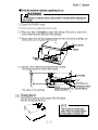
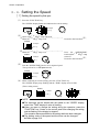
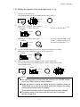
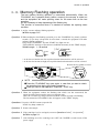
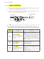
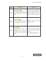
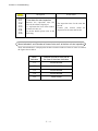
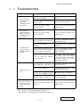
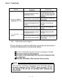
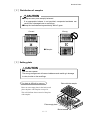
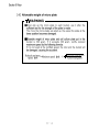
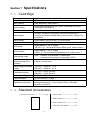
1
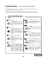
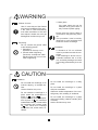
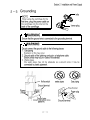
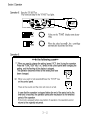
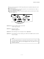
May 2007, Printed in Japan PLATE REFRIGERATED CENTRIFUGE INSTRUCTION AND SERVICE MANUAL To ensure proper operation of the centrifuge, be sure to read this manual carefully before operating it. Also, keep this manual handy so that you can refer to it at any time. NOTE ■The products being indicated in this Instruction Manual are designed for operators with expert knowledge and are intended only to be used by such qualified operators observing the indicated precautions for respective purposes. For persons lacking necessary expert knowledge, these products may be difficult to use properly and may even pose a danger to use. When the aforesaid persons lacking the necessary expert knowledge are using these products, do so under appropriate supervision and guidance of a qualified operator possessing the necessary expert knowledge. ■Do not distribute this manual within the U.S.A., Mexico, Canada and Australia as the products advertised in the manual shall not be distributed in these countries. F or information added or modified after June 2007, please contact your local dealer. KUBOTA CORPORATION 29-9 HONGO 3-CHOME,BUNKYO-KU,TOKYO 113-0033,JAPAN [34 Pages] H50249104 Safety Instructions The centrifuge and the manual indicate important information in order to ensure safe operation of the centrifuge and to prevent physical injuries and property damages. Be sure to understand the meanings of the following indications and follow the instructions. 1. Explanation of indication marks Indication Meaning WARNING It is a possibility of serious accident resulting in death or serious injury. CAUTION It is a possibility of accident resulting in slight or non-fatal injury or property damage. ■ "Serious injury" is defined as injuries such as loss of eyesight, burn (high/low temperature), electric shock, bone fracture, poisoning causing aftereffects, or any other injuries requiring long-term medical treatment at hospital. ■ "Non-fatal injury" is defined as burns, electric shock, or any other injuries which do not require long-term medical treatment at hospital. "Property damage" is defined as expansion damage related to damage to equipment or other property. 2. Explanation of pictorial marks Pictorial marks Meaning Indicates prohibition (things you must not do). Details are shown near the mark, using illustration or sentences. Indicates requirements (things you have to do). Details are shown near the mark, using illustration or sentences. Indicates caution, warning and danger. Details are shown near the mark, using illustration or sentences. This label indicates the risk of electric shock. Touching this attached part will cause an electric shock. This label indicates a hot section. Touching this attached part will cause an burn. Indicates that the power is on. It is indicated on the power switch and the circuit breaker. Indicates that the power is off. It is indicated on the power switch and the circuit breaker. page page 4−8.Spare Parts Supply・ ・ ・ ・ ・ ・ ・ ・・ ・ ・ ・ ・ ・ 4- 8 4−9.Manufacturer requirements at Repair Section 7. Specifications or Mainten ance・ ・ ・ ・ ・ ・ ・ ・ ・ ・・ ・ ・ ・ ・ ・ 4- 8 4−10.Product Preparation When Return ing 7−1.Centrifuge・ ・ ・ ・ ・ ・ ・ ・ ・ ・ ・ ・ ・ ・ ・ ・ ・ ・ ・ ・・ ・ 7-1 ・ ・ ・ ・ ・ ・ ・ ・ ・ ・ ・・ 7-1 7−2.Standard Accessories ・ Units for Repair or fo r Other Reasons ・ ・ ・ ・ ・ ・ ・ ・ ・ ・ ・ ・ ・ ・ ・ ・ ・ ・ ・ ・ ・ ・ ・ ・・ ・ ・ ・ ・4- 9 Contaminant Elimination Certificate ・ ・ ・ ・ ・ ・ ・ ・ ・ ・ ・ ・ ・ ・ ・ ・ ・ ・ ・ ・ ・ ・・ ・ ・ ・ ・ ・4-10 Section 8. Dispose of the centrifuge unit, rotor, and accessories・・・・・・・・・・・・8-1 Section 5. Troubleshooting 5−1.Caution Indicators・ ・ ・ ・ ・ ・ ・ ・・ ・ ・ ・ ・ ・ ・ ・ 5-1 E0・ ・ ・ ・ ・ ・ ・ ・ ・ ・ ・ ・ ・ ・ ・ ・ ・ ・ ・ ・・ ・ ・ ・ ・ ・ ・ ・ 5-1 ・ ・ ・ ・ ・ ・ ・ ・ ・・ ・ ・ ・ ・ ・ ・ 5-2 5−2.Alarm Ind icators・ E1・ ・ ・ ・ ・ ・ ・ ・ ・ ・ ・ ・ ・ ・ ・ ・ ・ ・ ・ ・・ ・ ・ ・ ・ ・ ・ ・ 5-2 E2・ ・ ・ ・ ・ ・ ・ ・ ・ ・ ・ ・ ・ ・ ・ ・ ・ ・ ・ ・・ ・ ・ ・ ・ ・ ・ ・ 5-2 E3・ ・ ・ ・ ・ ・ ・ ・ ・ ・ ・ ・ ・ ・ ・ ・ ・ ・ ・ ・・ ・ ・ ・ ・ ・ ・ ・ 5-2 E4・ ・ ・ ・ ・ ・ ・ ・ ・ ・ ・ ・ ・ ・ ・ ・ ・ ・ ・ ・・ ・ ・ ・ ・ ・ ・ ・ 5-3 E6・ ・ ・ ・ ・ ・ ・ ・ ・ ・ ・ ・ ・ ・ ・ ・ ・ ・ ・ ・・ ・ ・ ・ ・ ・ ・ ・ 5-3 E7・ ・ ・ ・ ・ ・ ・ ・ ・ ・ ・ ・ ・ ・ ・ ・ ・ ・ ・ ・・ ・ ・ ・ ・ ・ ・ ・ 5-3 C1・ ・ ・ ・ ・ ・ ・ ・ ・ ・ ・ ・ ・ ・ ・ ・ ・ ・ ・ ・・ ・ ・ ・ ・ ・ ・ ・ 5-4 C2・ ・ ・ ・ ・ ・ ・ ・ ・ ・ ・ ・ ・ ・ ・ ・ ・ ・ ・ ・・ ・ ・ ・ ・ ・ ・ ・ 5-4 C3・ ・ ・ ・ ・ ・ ・ ・ ・ ・ ・ ・ ・ ・ ・ ・ ・ ・ ・ ・・ ・ ・ ・ ・ ・ ・ ・ 5-4 C4・ ・ ・ ・ ・ ・ ・ ・ ・ ・ ・ ・ ・ ・ ・ ・ ・ ・ ・ ・・ ・ ・ ・ ・ ・ ・ ・ 5-4 C5・ ・ ・ ・ ・ ・ ・ ・ ・ ・ ・ ・ ・ ・ ・ ・ ・ ・ ・ ・・ ・ ・ ・ ・ ・ ・ ・ 5-4 ・ ・ ・ ・ ・ ・ ・ ・ ・・ ・ ・ ・ ・ ・ ・ 5-5 5−3.Troubleshooting・ Section 6. Rotor 6−1. Mounting RMP-62 Rotor・ ・ ・・ ・ ・ ・ ・ ・ ・ 6-1 ・ ・ ・6-2 6−2. RMP-62 Swinging Bu cket Rotor・ ・ ・ ・ ・ ・ ・ ・ ・ ・ ・ ・・ ・ ・ ・ ・ ・ ・ 6-2 [1]Specification ・ ・ ・ ・ ・・ ・ ・ ・ ・ ・6-3 [2]Distribution o f samp les・ ・ ・ ・ ・ ・ ・ ・ ・ ・ ・ ・ ・・ ・ ・ ・ ・ ・ ・ 6-3 [3]Setting plate・ ・ ・ ・6-4 [4]Allowable weight of micro p late・ Section 9. Parts List 9−1.Recommended Spare Parts・ ・ ・ ・ ・ ・ ・・ ・9-1 Index General Notes Be sure to follow them. Since large electrical and mechanical energies are present on the centrifuge and rotor, reasonable care is required for their handling. Otherwise, failure may occur resulting in property damages or fatal physical injuries. In order to prevent them from happening, be sure to follow the instruction given below. WARNING Maximum load Do not exceed the maximum load of rotor and bucket. The rotor or bucket used beyond the allowable load level can be damaged, thereby causing an accident. Maximum speed Keep the rotor and bucket speed below the maximum speed. Excessive speed may cause damage to the rotor, bucket and the centrifuge. The maximum speed depends on the rotor and bucket strength. Modification and unspecified parts Do not modify, nor use unspecified parts. Unauthorized retrofit of the centrifuge, rotor or bucket, or use of unauthorized parts for them can result in accidents. Hazardous material Do not put any hazardous material (explosive, chemically active, organic, or radiation containing material, or material contaminated by pathogenic microorganisms) as a sample of the centrifuge and do not place it closer than 30 cm to avoid a secondary accident should the centrifuge accidentally rotate and contact the material. While the centrifuge is in operation While the centrifuge is in operation, do not stand closer than 30 cm to avoid a secondary accident. id Do not open the lid when the rotor is spinning. Physical contact with the spinning rotor or bucket may cause serious injury. Sterilization Do not perform dry-heat or autoclave sterilization with temperatures higher than those specified. Otherwise, the rotor may deteriorate and cause an accident. Rotor and drive shaft during rotation Do not touch rotor and drive shaft during the rotation. Physical contact with the spinning rotor or drive shaft may cause serious injury. Damaged, corroded, rusted or deformed Discontinue use of the equipment when its rotor or the buckets found to have been damaged, corroded, rusted or deformed. Otherwise failure may occur. WARNING Lifetime of rotors Use of rotors beyond the lifetime may lead to breakage of the rotor. If the rotor is used continuously even after the lifetime of the rotor has expired, should the rotor get damaged an accident may occur. Grounding Do not connect the ground cable to the following places: 1. Gas piping Explosion or fire may occur. 2. Ground cable of lightning Conductor, or telephone cable. Electric shock may occur in the case of lightening. 3. Water pipes City water pipes may not be adequate as a ground since it may consist of plastic piping. Ensure that the ground cable is connected to the grounding terminal. This precaution must be strictly observed to avoid accidents due to electric shocks or leakage. Installation A clearance of 30 cm minimum must be provided around the centrifuge. If the centrifuge is driven into uncontrolled rotations due to a failure, secondary damage can result from energy absorbed by the rotation. CAUTION Installation Do not install the centrifuge on an inclined, slippery, or unstable surface. Violent vibration may occur. Do not install the centrifuge in a place where the temperature is below 10 or over 40 . A place with the ambient temperacan introduce ture beyond 40 undesirable build-up of heat inside the centrifuge and a place under can cause the centrifuge 10 malfunction and, as the result, accidents. Do not install the centrifuge in a dusty place. Do not install the centrifuge in a place with poor ventilation. Otherwise inside temperature of the centrifuge may rise, resulting in accidents. Do not install the centrifuge in a place with high humidity (relative humidity 85% or above). Leak or accident may occur. CAUTION Toxic or radioactive substances etc. When centrifuging of substances contaminated with pathogenic bacteria, or toxic or radioactive substances, always use containers that are pathogenic bacteria, toxic substance or radiation proof. Otherwise, infections, intoxication or radioactive exposure accidents may occur. Fasten a rotor Ensure that the rot or is firmly fastened to the drive shaft. If not positively held in place, the rotor or centrifuge can be damaged, thereby causing accidents. Bucket The same type buckets must be provided to every rotor yoke. If not positively held in place, the rotor or centrifuge can be damaged, thereby causing accidents. Tube Use the same type of tubes. The wrong arrangement will cause imbalance and resulting in damage to rotor, bucket or the centrifuge. Balance of sample Keep the load (of the sample, bucket, etc.) balanced. If an appropriate balance is not provided, unexpected accidents can result from a damaged rotor or centrifuge. Cleaning Do not use detergents exceeding the range of pH 5-8 or chlorine detergents for washing purposes. Corrosion may damage the rotor and bucket resulting in damage to the centrifuge. Caution plate Do not remove the caution plates. When a caution plate becomes dirty, blurred or peeled off, replace it with a new one(caution plates are available at charge). Usable Rotor WARNING (1) The rotors that can mount as of May 2007 : RMP-62 is exclusively used for Model PlateSpin. (2) Do not use any rotors other than RMP-62. If rotors other than RMP-62 is used, the rotors may be broken, resulting in a serious accident. (3) This information is subject to addition or change. For information after June 2007, please contact your local dealer. Lifetime of rotors WARNING Use of rotors beyond the lifetime may lead to breakage of the rotor. If the rotor is used continuously even after the lifetime of rotors has expired, should the rotor get damaged, the main unit of the centrifuge suddenly may start to rotate; this could result in an accident causing injury or death. Lifetime of rotors is 7 years after the delivery. When 7 years have passed after the delivery, discontinue operation of the centrifuge to replace the rotor with a new one. Earlier replacement, however, is required if any corrosion, lowered strength, flaw or deform due to incorrect operation is detected on the rotor. In such case, contact your local dealer and be sure to have the rotor checked before reusing it. Ⅳ Number of times allowed for autoclaving of rotor WARNING Stop the use of the rotor immediately when it is used beyond the number of times allowed for autoclaving. Otherwise, the rotor may deteriorate by the heat generated by autoclaving, resulting in deformation or destruction. Should the rotor get damaged, the main unit of the centrifuge suddenly may start to rotate; this could result in an accident causing injury or death. The number of times allowed for autoclaving of each rotor should be deemed as follows. When the following conditions have been met, discontinue operation of the centrifuge to replace the rotor with a new part. Earlier replacement, however, is required if any corrosion, lowered strength, flaw or deform due to wrong operation is detected on the rotor. In such c ase, contact your local dealer and be sure to have the rotor checked before reusing it. [1] Number of times allowed for autoclaving and temperature of rotor Rotor Temperature of autoclave Number of times allowed for autoclaving 121 ℃ 50 times RMP-62 [2]Recording autoclave After each autoclave process, be sure to record the following (1)to (3) to control how many times the autoclave is executed. (1)Date (2)Temperature of autoclave (3)Time of autoclave You can take advantage of using the "Autoclave record table" attached to this manual. Ⅴ Section 2 Installation and Power Supply 2−1. Unpacking When the centrifuge is taken out of a corrugated carton box, check the following. (1)Upon receiving the centrifuge, examine it for any visible damage caused during transportation. If any is found, contact the dealer immediately. (2)Confirm that all the accessories listed in [7 - 2. Standard Accessories] are included with the delivery. Refer to page 7-1. 2−2. Place of installation WARNING A clearance of 30 cm minimum must be provided around the centrifuge. If the centrifuge is driven into uncontrolled rotations due to a failure, secondary damage can result from energy absorbed by the rotation. CAUTION Do not install the centrifuge on an inclined, slippery, or unstable surface. Violent vibration may occur. When installing this centrifuge, keep 3meters or more away from AM radio. Noise generated by this centrifuge causes the sound of AM radio deteriorated. 2−3.Movement of centrifuge WARNING ● Never move the centrifuge while the rotor is rotating or while the rotor is attached to the centrifuge. Otherwise, the drive shaft may become bent or the rotor and the bucket may come off, resulting in an accident or damage to the centrifuge. ● Ensure that rotor and bucket are removed from the centrifuge and that the power cord is disconnected from the wall outlet. ● Moving the position of the centrifuge while the power is turned on may cause electrification accident or functional failure of the centrifuge. Cont’d. on next page. 2−1 Section 3 Operation 3−1. Cautions of Operation W hen using this centrifuge, observe the contents of the Section "General Notes" being described in the front part of this document and the precautions given in respective sections. 3−2. Operation Operation 1. Turn on the "POWER" switch. Operation 2. After the "STOP" lamp on the control panel lights, press the "OPEN" button. Operation 3. Mount the rotor on the drive shaft. Refer to Section 6. Operation 4. Place the sample in the buckets. Refer to Section 6. NOTE If the lid is not closed properly the centrifuge is not able to start. Make sure the lid is closed firmly. Operation 5. Close the lid firmly. Operation 6. Proceed to operation 8 when operating with the same setting values as before. Operation 7. Set the respective parameters. ・Set to required speed. Refer to page 3-6. ・Set to required time. Refer to page 3-8. ・Set braking force during deceleration and acceleration speed with the "ACC/DEC" key. Refer to page 3-9. ● Refer to page 3-10 to carry out Flashing operation. NOTE Press the "SPEED/TIME" knob to check the "centrifugal force" of the set speed or "speed" of the set centrifugal force. Cont’d. on next page. 3−1 Sectio n 3 Operation When the rotor has stopped, the "STOP" lamp flashes and an sound that informs the end of the operation is issued. ● The "Sound that informs the end of the operation" can be selected from the 5 kinds + Sound none. Refer to page 3-15. ● The "Alarm Indicators" to show the end of the operation can be selected from the 5 kinds. Refer to page 3-18. Operation 10. Press the "OPEN" button to open the lid. "STOP" lamp remains lit. Operation 11. Remove the sample. Refer to page 3-17. Operation 12. If the centrifuge is to be used again, return to Operation 4. Operation 13. After finishing use of the centrifuge, turn "OFF" the "POWER" switch to turn off the power supply. NOTE The setting parameters are memorized when the power is turned off, and they will be called up and displayed when the power will be turned on next time. 3−3 Section 3 Operation 3−4.Setting the Speed [1]Setting the speed by the rpm (1)Press the "FUNCTION" key. The "SPEED" display flashes and indicates the current setting. SPEED ×100rpm FUNCTION ×10 g (2)Check if the〈× 10 g 〉lamp turned off. ① When the〈× 10 g 〉lamp is off ・・ ・・ ・・ ・・ ・・ ・・ ・ ・・ ・・ ・ Proceed to the Procedure(3). SPEED ×100rpm ×10 g ・・ ・・ ・・ ・・ ・・ ・・ ・ ・・・ ・ ・ Press the "SPEED/TIME" ② When the〈× 10 g 〉lamp is on・ knob and the〈× 10 g 〉lamp SPEED turns off. ×100rpm Proceed to the Procedure(3). ×10 g (3)Turn the "SPEED/TIME" knob to set to required speed. The speed can be set 100 rpm intervals. SPEED ×100rpm ×10 g (4)When continuing on to time setting, press the "FUNCTION" key. The "SPEED" display stops flashing and the "TIME" display starts to flash. (Timer setting status) TIME SPEED FUNCTION ×100rpm min ×10 g se c NOTE ● The centrifuge can be started with the speed on the "SPEED" display, even if the "TIME" display of value is flashing. ● When you want to change the setting during the operation, press the "FUNCTION" key 2 times on the control panel after changing the setting, and the flashing of the display is stopped. The operation becomes shifted to the setting that have been changed. ● The setting order of the speed and the timer can be changed. Refer to page 3-16. 3−6 Section 3 Operation [2]Setting the speed by the centrifugal force ( × g) (1)Press the "FUNCTION" key. The "SPEED" display flashes and indicates the current setting. SPEED ×100rpm FUNCTION ×10 g (2)Check if the〈× 10 g 〉lamp turned on. ① When the〈× 10 g〉lamp is on ・・ ・・ ・・ ・・ ・・ ・ ・・・ ・Proceed to the Procedure (3). SPEED ×100rpm ×10 g ・・ ・・ ・・ ・・ ・ ・・・ ・Press the "SPEED/TIME" knob ② When the〈× 10 g〉lamp is off・・ and the〈× 10 g 〉lamp turns on. SPEED Proceed to the Procedure (3). ×100rpm ×10 g (3)Turn the "SPEED/TIME" knob to set to required centrifugal force reading. Indications on the "SPEED" display are at 10 × g intervals. SPEED ×100rpm ×10 g (4)When continuing on to time setting, press the "FUNCTION" key. The "SPEED" display stops flashing and the "TIME" display starts to flash. (Timer setting status) TIME SPEED FUNCTION ×100rpm min ×10 g sec NOTE ● The centrifuge can be started with the speed on the "SPEED" display, even if the "TIME" display of value is flashing. ● When you want to change the setting during the operation, press the "FUNCTION" key 2 times on the control panel after changing the setting, and the flashing of the display is stopped. The operation becomes shifted to the setting that have been changed. ● The setting order of the speed and the timer can be changed. Refer to page 3-16. 3−7 Section 3 Operation 3−5. Setting the Timer (1)Pressing the "FUNCTION" key 2 times, the "TIME" display flashes and indicates the current setting. The timer is able to be set up. min FUNCTION sec (2)Pressing "SPEED/TIME" knob changes the settable range of centrifuging time as described below. Set to the range as required. Factory default,the range is set minutes. ① Setting minutes Settable range Setting unit 1-99 minutes min 1 minute sec ② Setting seconds Settable range Setting unit 1-99 seconds min sec 1 second ③ HOLD It will continuously operate regardless of the timer. When set to hold, both "min" and "sec" lamp will be turn off. (3)Turning the "SPEED/TIME" knob changes the indication on the display. Set to the time required. min sec min sec (4)Press "START" key on the control panel. The operation will be started. When started, the display will diminish and stop at point 0. NOTE ● The centrifuge can be started with the time on the "TIME" display, even if the display of value is flashing. ● When you want to change the setting during the operation, press the "FUNCTION" key on the control panel after changing the setting, and the flashing of the display is stopped. The operation becomes shifted to the setting that have been changed. ● The speed and the timer can be set in this sequence or vice versa. As for the change of the setting, please refer to page 3-16. 3−8 Section 3 Operation 3−6.Setting the acceleration・deceleration When blowing-up of samples is feared, adjust the acceleration and the deceleration setting by pressing the "ACC/DEC" key. RAPID acceleration [Ex.] SPEED SLOW acceleration The acceleration characteristics changes to the RAPI D from SLOW at 1,000 rpm. 1000rpm N TIME Natural decelerati on RAPID SLOW deceleration deceleration NOTE You can set the natural deceleration starting speed N. Refer to page 3-14. ACC DEC ACC:RAPID(“ RAPID ” acceleration ) DEC:RAPID (“ RAPID ” deceleration ) ACC DEC ACC :RAPID(“ RAPID ” acceleration ) DEC :SLOW (“ SLOW ” deceleration ) ACC DEC ACC:SLOW(“ SLOW ” acceleration ) DEC:RAPID(“ RAPID ” deceleration ) On Off ACC DEC ACC:SLOW (“ SLOW ” acceleration ) DEC:SLOW (“ SLOW ” deceleration) 3−9 Section 3 Operation 3−7.Flashing operation The flashing operation continues as long as the "FLASHING" key is kept depressed. The flashing operation decelerates and stops when the "FLASHING" key is released. Operation 1. At first, execute ordinary Operation 1 - 5 in the[3-2.Operation]. Refer to page 3-1. Operation 2. Keep the "FLASHING" key depressed. Lamp on the "START" key lights on. "F(FLASHING)" and time of operation are indicated alternately on the "TIME" display. Settable range:1 - 99 second [Ex.]10 seconds min sec ⇔ min sec * As for the speed, the rotor can be rotated at its maximum speed. If the set va lue does not reach the maximum speed, the rotor rotates only up to the set value. * As for the acceleration rate, the rapid acceleration characteristics will be selected. * As for the deceleration strength, the rapid deceleration characteristics will be selected. FLASHING Operation 3. The operation will stop when you rele ase the "FLASHING" key. "FLASHING" and "START" lamp lights off. The indication on the "TIME" display will show the value a t the time when the "FLASHING" key was released, until the lid will be opened. Operation 4. Press the "OPEN" button to open the lid. "STOP" key lamp remains lit. Operation 5. Remove the sample. Operation 6. If the centrifuge is to be used again, return to Operation 4 in the[3-2.Operation ] . Refer to page 3-1. Operation 7. After finishing use of the centrifuge, turn "OFF" the "POWER" switch to turn off the power supply. 3−10 Section 3 Operation 3−8.Memory Flashing operation The last ordinary flashing operation is memorized automatically. When the "FLASHING" key is pressed shortly (within a second), the memory is called out and the equipment will make spinning down for the same time as the last operation. It is not necessary to keep depressing of the flashing key. This function is convenient when it is desired to maintain the spinning down condition. Operation 1. At first, execute ordinary flashing operation. Refer to page 3-10. Operation 2. When making the 2nd flashing operation, press the "FLASHING" key shortly (within a second). (If you keep it depressed for more than a second, the equipment will make ordinary flashing operation.) Lamp on the "FLASHING" key and "START" key light turn on. "F(FLASHING)" and time of operation are indicated alternately on the "TIME" display. Settable range :1 - 99 second [Ex.]10 seconds min sec ⇔ mi n sec * As for the acceleration rate, the rapid acceleration chara cteristics will be selected. * As for the deceleration strength, the rapid deceleration characteristics will be selected. Release the key within a second. FLASHING NOTE ● Press the "FLASHING" key once again, in case that you want to check the operation time during the flashing operation. ● When you want to halt operation, Press the “STOP" key. Operation 3. When the equipment reaches the flashing time which was last me morized, the operation will be decelerated to come to a complete stop. Then, the "START" key lamp will turn off and the "STOP" key lamp will flashing. The last memorized "FLASHING" time will appear on the "TIME" display. Operation 4. Press the "OPEN" button to open the lid. "STOP" key lamp remains lit. Operation 5. Remove the sample. Operation 6. If the centrifuge is to be used again, return to Operation 4 in the[3-2.Operation ]. Refer to page 3-1. Operation 7. After finishing use of the centrifuge, turn "OFF" the "POWER" switch to turn off the power supply. 3−11 Section 3 Operation 3−9.Setting the Function As for this product the following setting is produced. Choose the item you want to set up, and press "SPEED/TIME" knob. The page where the content is written is referred to. (1)Pressing the "SPEED/TIME" knob while holding down the "FUNCTION" key . FUNCTION SPEED (2)The used number of times of the centrifuge is displayed. [ Ex.]186 times TIME ×100rpm min ×10 g sec SPEED (3)Setting the Rotation Radius Refer to Page 3-13. [Ex.]100 mm TIME ×100rpm min ×10 g sec TIME SPEED (4)Setting the "SLOW" deceleration. Refer to Page 3-14. [Ex.]300rpm ×100rpm min ×10 g sec SPEED (5)Setting the Sound that informs the end of the operation. Refer to Page 3-15. [Ex.]1 TIME ×100rpm min ×10 g sec SPEED (6)Reverse of setting order of the Speed and the Timer. Refer to Page 3-16. [Ex.]0 TIME ×100rpm min ×10 g sec SPEED (7)Setting the Reminder alarm. Refer to Page 3-17. [Ex.]ON TIME ×100rpm min ×10 g sec TIME SPEED (8)Setting the Indicators for the end of the operation. Refer to Page 3-18. [Ex.]1 ×100rpm mi n ×10 g sec ■ After setting any one of the above, please return the display to the previous indication of "SPEED" and "TIME". To do above, press the "SPEED/TIME" knob while holding down the "FUNCTION" key. 3−12 Section 3 Operation [1]Setting the Rotation Radius To obtain more accurate centrifugal force, adjust the rotation radius to that of the rotor buckets. Factory default : 100 mm. (1)Pressing the "SPEED/TIME" knob while holding down the "FUNCTION" key . The used number of times of the centrifuge is displayed. FUNCTION (2)Pressing the "SPEED/TIME" knob several times and let indicate "r" on the left side of the "SPEED" display. The "SPEED" and "TIME" display indicates the current setting. Unit : mm Refer to Page 3-12. [Ex.]The rotation radius is 100 mm. SPEED TIME ×100rpm min ×10 g sec 3 digits 2 digits 1 digit (3)Turn the "SPEED/TIME" knob to set to the rotation radius of the rotor bucket to be used for operation. The settable range is from 50 to 120 mm. TIME SPEED ×100rpm min ×10 g sec 2 digits 1 digit (4)Press the "SPEED/TIME" knob while holding down the "FUNCTION" key. The display returns to the previous Speed and Time indication after the setting (rotation radius) is saved. FUNCTI ON NOTE The rotation radius can not be stored in the memory, when the power supply is turned off without returning the display to the previous indication. 3−13 Section 3 Operation [2]Setting the "SLOW" deceleration You can set the natural deceleration starting speed N by the following method. Factory default,it is set as 0 rpm. The setting range of "N" is from 0 to 2,500 rpm. (B)N= 1,000 rpm or less (A)N=1,000 rpm or more speed speed RAPID r pm N r pm Natural decel eration 1000 RAPID 1000 N SLOW The deceleration characteristics changes t o the SLOW from RAPID at 1, 000 rpm. Natural decel eration TIME TIME (1)Pressing the "SPEED/TIME" knob while holding down the "FUNCTION" key. The used number of times of the centrifuge is displayed. (2)Pressing the "SPEED/TIME" knob several times and let indicate "Fr " on the "TIME" display. The "SPEED" display indicates the current setting of the natural deceleration speed. Unit : rpm Refer to Page 3-12. [Ex.] Setting is the 0 rpm. TIME SPEED ×100rpm min ×10 g se c (3) Turn the "SPEED/TIME" knob to set the natural deceleration speed. [ Ex. ] Setting the 300 rpm. SPEED TIME ×100rpm min ×10 g sec (4)Press the "SPEED/TIME" knob while holding down the "FUNCTION" key. The display returns to the previous Speed and Time indication after the setting ( Natural deceleration speed) is saved. FUNCTI ON 3−14 Section 3 Operation [5]Setting the Reminder alarm The alarm reminds you every minute when samples are left inside the centrifuge after completion of the operation. The reminder alarm goes off when opening the lid or performing some operations. Factory default : [ ON ] (1)Pressing the "SPEED/TIME" knob while holding down the "FUNCTION" key. The used number of times of the centrifuge is displayed. (2)Pressing the "SPEED/TIME" knob several times and let indicate "bO " on the "TIME" display. The "SPEED" display indicates the current setting of the reminder ON or OFF. (see the figure below) Refer to Page 3-12. [Ex.]Reminder alarm : ON TIME SPEED ×100rpm min ×10 g sec Reminder alarm "SPEED" display. ○ On × OF (3)Turn the "SPEED/TIME" knob to change the number. [Ex.]Reminder alarm : OFF TIME SPEED ×100rpm min ×10 g sec (4)Press the "SPEED/TIME" knob while holding down the "FUNCTION" key. The display returns to the previous Speed and Time indication after the setting (reminder on or off) is saved. FUNCTION 3−17 Section 3 Operation [6]Setting the Indicators for the end of the operation Completion of the operation is indicated not only with an alarm but also with the "SPEED" and "TIME" displays. The "Alarm Indicators" can be selected from the 5 kinds. Factory default : [ 1 ] (see the figure below). (1)Pressing the "SPEED/TIME" knob while holding down the "FUNCTION" key. The used number of times of the centrifuge is displayed. (2)Pressing the "SPEED/TIME" knob several times and let indicate "bL " on the "TIME" display. The "SPEED" display indicates the current setting of the number (see the figure below). Refer to Page 3-12. [Ex.]Number : 1 SPEED TIME Numbers ×100rpm min ×10 g sec "SPEED" and "TIME" display 0 After [Setting value]lights, [Remained period of the operation.]lights 1 After [Setting value]flashing, [Remained period of the operation.]lights 2 [88][88]flashing 3 [−−] [−−]flashing 4 [E] [nd]flashing (3)Turn the "SPEED/TIME" knob to change the number. SPEED TIME ×100rpm min ×10 g se c (4)Press the "SPEED/TIME" knob while holding down the "FUNCTION" key. The display returns to the previous Speed and Time indication after the setting (Numbers) is saved. FUNCTION 3−18 Service 4−1.Daily Inspection Section 4 WARNING If any abnormality is found during routine daily inspections, discontinue centrifuge operation, use the "POWER" switch to turn the machine OFF, disconnect the power cable, attach "DO NOT USE" labels to the rotor and the outside of the centrifuge, and contact your nearest dealer to request a centrifuge inspection before resuming operation of the equipment. If the centrifuge is used after discovering any abnormality, an accident could occur, possibly leading to serious damage or accidents involving physical injury. Checkpoint Action taken Check whether the rotor locking nut is properly tight. Retighten, if either of these is loose. For details, refer to "Mounting the Rotor" in the rotor instruction manual. Refer to Section 6. To inspect, mount buckets on the swinging bucket rotor when it is stopped, and lift up the buckets manually. If the buckets do not move smoothly and freely, clean the bucket grooves and trunnion pins of the rotor yoke using alcohol. Contact your local dealer and make an appointment for an authorized inspection if these parts fail to operate smoothly even after lubricant has been applied. Refer to Page 4-5. Check carefully for any cracks, evidence of corrosion, rust or deformation on the rotor and buckets. Do not use the rotor or buckets if any cracks, corrosion, rust or deformations are found. Contact your local dealer for an inspection. Check that no foreign material or water is present in the chamber. Remove any foreign material or water before operating the centrifuge. Check that the lid hook is locked. If the lid lock does not work, discontinue operation of the centrifuge. Contact your nearest dealer for a centrifuge inspection. Check that the screws fixing the lid hinges are not loose. If the screws fixing the lid hinge are loose or have been removed, the lid may come off when the buckets are thrown off and the broken pieces may cause injury to the persons in the vicinity of the centrifuge. If the lid hinge is not fixed firmly, stop centrifuge operation. Stop operation promptly and contact your local dealer for inspection. Check that the grounding wire is correctly connected. Refer to Page 2-3. Check that all knobs, displays, lamps and switches operate correctly. If any do not operate correctly, contact your local dealer for an inspection. Refer to Page 1-1 and 1-2. Check that the centrifuge is placed horizontally. Refer to page 2-1. 4−1 Section 4 Service 4−2.Monthly Inspections [1] Inspect the rotor WARNING Perform a monthly careful inspection of the rotor appearance. Check for any deformation or damage, including the interior and bottom of the holes. If any abnormality whatsoever is found, there may be significant damage or corrosion of the rotor that could lead to serious damage or accidents involving physical injury. Stop operation at once, put "DO NOT USE" labels on the rotor and centrifuge lid, and contact your local dealer. [2]Clean the rotor and buckets Remove the rotor from the shaft, and clean it. Refer to Page 4-3. [3]Clean the chamber interior Refer to Page 4-3. 4−3. Annual Inspection Annual Inspection (fee required) For the following inspection items, please call your local dealer and set up an appointment for a periodical inspection. Motor Speed control Rotor and bucket Imbalance lid Electric current Chamber Insulation Speed meter Install the centrifuge Timer 4−2 Section 4 Service [2]Cleaning the rotor, buckets and tube rack CAUTION Do not use detergents exceeding a pH range of 5 - 8, or chlorinated detergents normally used for washing. Corrosion may damage the rotor, bucket, or tube rack, resulting in damage to the centrifuge that may lead to serious additional damage or accidents involving physical injury. NOTE Do not allow any spilt samples to remain on any surfaces, otherwise rust or corrosion may occur. Also, if sample spillage is left between the rotor and shaft, later detachment of the rotor may become problematic. 1) If sample spillage has occurred, remove the rotor, buckets, and tube rack from the centrifuge, and wash the affected items with a neutral detergent and warm water. Then rinse the items with the distilled water and thoroughly dry them before use. 2) If water has accumulated inside the rotor, place the rotor with its bottom side up and allow it to dry completely. 3) If a sample has spilled onto the drive shaft, wipe it off using a cloth moistened with a small amount of a neutral detergent and then clean away all detergent traces using a cloth moistened with water. Then, dry the surfaces completely before using the machine. [3]Sterilization of rotor, buckets and tube rack WARNING Do not heat the rotor, buckets, or tube rack above 121 ℃ for sterilization or disinfection purposes. Also, do not use an autoclave for dry heat sterilization, since excessive heat may deleteriously affect the strength of the rotor, buckets, or tube rack, resulting in breakage of the rotor, buckets, or tube rack, causing serious damage or accidents involving physical injury. Yet, You can conduct up to 50 times of autoclave sterilizations of the RMP-62 rotor and bucket at 121 ℃ . Refer to page Ⅴ . To disinfect the rotor, buckets, or tube rack, a 70 % ethanol solution, or ultraviolet radiation, is recommended. 4−4 Section 5 Troubleshooting 5−1.Caution Indicators When "one of the c odes" shown in the table below a ppears on the "TIME" display, follow the appropriate instruction in the table to take corrective measures. [Ex.] “TIME"display Control panel TIME mi n sec Caution Indicators Checkpoint Action taken E0 Setting speed alarm An error occurs immediately after the "START" key is pressed when the speed setting is more than 2,500 rpm (this may happen when centrifugal force after changing rotation radius is changed to spee d). Pressing the "SPEED/TIME" key makes the centrifuge auto-correct the speed to 2,500 rpm. 5−1 Section 5 Troubleshooting 5−2.Alarm Indicators (1)When trouble occurs during operation, the “TIME" display flashes to show the alarm. The alarm indicators are mentioned in the table below. (2)When any of the ala rm indicators turn on during ope ration (w hen the rotor is spinning), the rotor immediately decelerates and stop s. [Ex.]“TIME"display Control panel TIME min sec NOTE The equipment is inoperative while any of the alarm indicators is turned on. Alarm Indicators Checkpoint Action taken E1 Imbalance alarm This indicator flashes and the rotor stops rotation when excessive vibration is detected. ①Balance the load (samples or bucket). ②Remove dust and dirt from the sliding surface and apply grease so that the bucket on the swing rotor swings up smoothly. Contact your local dealer for inspection when this alarm continues to flash even after taking the above measures. E2 Lid open alarm This indicator lights when the lid is open. Close the lid completely. When the alarm recurs, contact your nearest dealer for inspection. E3 Inverter alarm This indicator flashes when abnormal signal comes out from the inverter. After the rotor stops spinning, turn off power supply once and turn on the power after about 30 seconds. When the alarm recurs, contact your nearest dealer for inspection. 5−2 Section 5 Troubleshooting Alarm Indicators Checkpoint Action taken E4 Speed sensor alarm This indica tor flashes whe n the self-inspection function detects the fault or abnormality in the speed sensor. After the rotor stops spinning, turn off power supply onc e and turn on the power after about 30 seconds. When the alarm recurs, contact your nearest dealer for inspection. E6 Over speed alarm Flashes to stop the rotation when the maximum speed of the corresponding rotor is exceeded. Contact your local dealer for inspection when this alarm continues to flash. E7 Speed alarm This code appears when the equipment did not start its operation within 5 seconds after the "START" key was pressed by such causes as electric circuit failures. After the rotor stops spinning, turn off the power supply once and turn on the power after about 30 seconds. If the alarm recurs, contact your nearest dealer for inspection. Cont’ d. on next page. 5−3 Section 5 Troubleshooting Alarm Indicators Checkpoint Action taken C1 C2 C3 C4 C5 Time alarm for rotor inspection Because the inspection time has arrived, the alarm is displayed. 1-5 represents the level of the number of times of rotor use. As for the details, please re fer to the following. The inspection time for the rotor has arrived. Contact your nearest dealer for inspection of the rotor and bucket. "Alarm Indicators" and "Number of times of rotor use" at the time of rotor inspection Each "Alarm Indicator" is displayed at the time when the number of times of rotor use reaches the figures shown below. Alarm Indicators Number of times of rotor use at the time of the alarm indicators C1 25,000-25,050 C2 40,000-40,050 C3 50,000-59,999 C4 60,000-69,999 C5 From 70,000 5−4 Section 5 Troubleshooting 5−3.Troubleshooting Problem 1. The "STOP" key lamp does not lit even if the "POWER" switch is turne d on. 2. The power is turned off immediately even if the "POWER" switch is turne d on. 3. The lid does not open even if the "OPEN" button is pushed. 4. The motor does not spin. 5. The speed does not reach the set value even if the knob is turned. Checkpoint Action taken Is the power plug disconnected from the power outlet? Insert the power plug into the socket. Is power supplied to the socket or knife switch? Inspect the power supply. Is the power supply voltage correct? (Note1) Use a power supply in the correct voltage range. Is the power supply voltage correct? (Note1) Use a power supply in the correct voltage range. Is the "POWER" switch turn on ? Pull up the "POWER" switch to turn the power on. Is the <STOP> lamp lit or flashing? Wait until the rotor is completely stopped. Does it open when the power switch is turne d off and turned on once again in 10 seconds? Check if an imperfect contact is not occurring with the power cable connection. Can you push the "OPEN" button smoothly? Afte r open the lid with pulling the string of the lid extreme release and collect the sample, and then contact your local dealer for inspection. Is the"POWER" switch turn on? Pull up the "POWER" switch to turn the power on. Is the <STOP> lamp lit? Go back to Problem 1. & 2. and check the power supply. Is the alarm <E1, E2, E3, E4, E6, E7> flashing on the Refe r to pages 5-2 and 5-3. Is the lid closing ? (Note 2) Close the lid firmly. Is the power supply voltage low ? (Note 1) Use a power supply in the correct voltage range. Note 1: Read [2-4. Power Requirements] on page 2-1. Note 2: Read [3-3. Opening and Closing the lid] on page 3-4. Cont ’ d. on next page. 5−5 Rotor 6−1.Mounting RMP-62 Rotor Section 6 W hen you purchase the centrifuge and rotor together, the rotor will be in the state of being mounted on the centrifuge. W hen replacing the rotor or when the rotor is removed for some reason, refer to the mounting procedure in the manual for each rotor. CAUTION Make sure that the rotor yoke is firmly fastened to the drive shaft w ith the rotor locking nut. Since the rotor is not fastened onto the shaft when these parts are lo ose,exces sive v ibrations will occur and damage the equipment and the rotor may fly off inflicting phys ical injury. 1. To install the rotor, match the rotor groove with the pin of the drive shaft. After mounting the rotor, the screw is protruding 8 mm from the center hole of the rotor. 2. Fix the rotor by tighte ning the rotor locking nut. Rotate the nut clockwise using the T-type box wrench (10mm) etc. 3. After installation of the rotor, hold the rotor yoke and attempt to move it up and down to ensure that there is no play. T-type box wrench Rotor locking nut Rotor yoke Center hole of rotor Drive pin Center axis of rotor Drive shaft Groov e Screw Drive shaft Driv e pin Do not start the operation when the rotor locking nut is removed. W hen the drive pin is not aligned with the pinhole of the rotor bottom or the rotor is incompletely fastened to the drive shaft, the screw is protruding only 3mm from the center hole of the rotor. In such a case, re-install the rotor. 6−1 Section 6 Rotor 6−2.RMP-62 Swinging Bucket Rotor [1]Specification Calculating Centrifugal Force for RMP-62 R2 RX A Because of the size of the micro plate ,the radius of rotation differs between the center and the both ends with respect to the rotation axis,resulting in the difference in the centrifugal force .The centrifugal force of the place A (cm) Distant from the center of a bucket can be calculate d in accordance with the formula, where the rotation radius R shall be substituted with the Rx to be obtained by the formula mentioned below. 2 2 R(cm)= X R (cm)+A (cm) 1 R1 where,R: 1 Radius rotation Minimum (cm ) RX:Actual rotation radius in a position which is A cm away from the center of the bucket. Number of wells Number of Plate 96 6 *1 PL Micro plate 86×128×52 96 2 PL Deep well plate 86×128×52 96 2 PL PCR plate 86×128×52 Plate Material *2 Plate Sizes mm Allowable Speed rpm 2, 500 RCF ×g * 3*4 Buckets 700/820 Bucket is included with this rotor. Radius R1/R2 cm Allowable load gram *5 10/11. 7 300 *1 The maximum speed drops when the step number increases, although a micro plate is possible to piling 3 steps. When pile up the micro plate to each bucket, use it after the sufficient test for the strength of the plate is made. The more the micro plates are piled up, the easier the plate at the lower position becomes damaged. Refer to Page 6-4. *2 PL : Plastic *3 The left side is the RCF of radius R1. The right side is the RCF of radius R2. *4 The value of the RCF that is indicated to the display is showing the value that cut the lower 2 digits. Refer to Page 3-13. *5 Allowable load per bucket. This load includes the weight of the sample, plate etc. The weight of bucket is not included in the allowable load. NOTE Never use any user-modified rotors or buckets, or adapters other than those specified by us (including adapters made by unauthorized users). We shall in no event be liable for any accidents or trouble incurred due to the use of such unauthorized parts. 6−2 Section 6 Rotor [2] Distribution of samples CAUTION ■ Keep the load (of the sample) balanced. If an appropriate balance is not provided, unexpected accidents can result from a damaged rotor or centrifuge. ■ Keep the load balanced symmetrically within 5 gram. Correct Wrong ● Sample [3]Setting plate CAUTION Use the same plates. The wrong arrangement will cause imbalance and resulting in damage to rotor, bucket or the centrifuge. If a plate is difficult to remov e, Plate with the sample Place an extra empty plate in the bucket and place the plate with samples on top of it. This will facilitate later re moval of the plate with samples. 0 Extra empty plate Bucket 6−3 Section 7 Specifications 7−1.Centrifuge Max. speed Max. RCF Max. Capacity 2,500 rpm 700 × g Deep well plate 2, Micro plate 6 Control system Invertor Microprocessor control, Speed, Centrifugal force, time, acceleration / deceleration Acceleration/Deceleration Rapid, Slow, 4 ways of switching Alarm display Lid open, Imbalance, Over speed, Function for detecting an occurrence of electrical abnormality in speed sensor, invertor, Lid rock, Motor Speed setting Speed indication Digital display, 200-2,500 rpm, in 100 rpm steps Digital display, 0-2,700 rpm, in 100 rpm steps RCF setting Digital display, in 100 × g steps 100-700 × g(The centrifugal force differs by the rotation radius. ) RCF indication Digital display, in 100 × g steps 0-820 × g(The centrifugal force differs by the rotation radius. ) Timer setting range From 1 second to 99 seconds (1 second step) 1 minutes to 99 minutes(1 minutes step) HOLD Setting the Sound that informs the end of the operation 5 kinds + Sound none Rated voltage and Rated current 110-115 V 50/60 Hz 1.3 A 220-230 V 50/60 Hz 0.6 A Total heat produced 110-115 V 60 W 220 kJ/h 220-230 V 70 W 252 kJ/h Dimensions, Weight Safety regulation 35 (W) × 42(D) × 32(H) cm, 26 kg IEC 61010-2-020, CLASS Ⅰ Operation environment Temperature : 10 to 40 ℃ Atmospheric pressure : 70 to 106 kpa (700 to 1,060 mbar) Humidity : 30 to 85% 7−2.Standard Accessories 1. Instruction manual・ ・ ・ ・ ・ ・ ・ ・ ・ ・ ・ ・ ・ ・ ・ ・ ・1 Copy 2. Power cable・ ・ ・ ・ ・ ・ ・ ・ ・ ・ ・ ・ ・ ・ ・ ・ ・ ・ ・ ・ ・ ・ ・1 Pc. 3. RMP-62 Rotor・ ・ ・ ・ ・ ・ ・ ・ ・ ・ ・ ・ ・ ・ ・ ・ ・ ・ ・ ・1 Pc. 4. Rotor locking nut・ ・ ・ ・ ・ ・ ・ ・ ・ ・ ・ ・ ・ ・ ・ ・ ・1 Pc. 5. Grease (No.067-0040)・ ・ ・ ・ ・ ・ ・ ・ ・ ・ ・1 Pc. 7−1 Section 8 Dispose of the centrifuge unit, rotor, and accessories Dispose of the centrifuge unit, rotor, and accessories according to local practices for the disposal of industrial waste. If you encounter problems concerning prope r disposal, contact your nearest dealer. If the centrifuge unit, rotor, or accessories to be discarded are contaminated with radioactive, explosive, toxic or infectious substances that may be harmful to people's health, you must notify the waste handlers concerning the details of such contaminants. 8−1 Section 9. Parts List 9−1.Recommended Code No. Spare Parts Description Use , standard Q'ty 014-0061 Micro switch VX-016-1A3 1 014-0071 Micro switch V-102-1A5 1 029-0010 Speed sensor 029-0034 CTL PC board 066-0028 CPU ROM 014-0056 Invertor VFNC1S-1002P, For 100-115 V 1 014-0057 Invertor VFNC1S-2002PL, For 200-240 V 1 017-0009 motor KC128 0.18kW 1 014-0059 Solenoid CKD DS-08A DC5V 1 014-4470 Circuit protector W28 × Q1A-8, For 100-115 V 1 014-0065 Circuit protector W28 × Q1A-5, For 220-230 V 1 014-0099 Switching regulator VS10C-5, For 100-115 V 1 014-0063 Switching regulator ZWS15-5/J, For 220-230 V 1 014-0064 Power switch AJ921001WW3F 1 014-8130 Noise Filter For 220-230 V 1 014-8120 Noise Filter For 220-230 V 1 1 Without ROM 1 1 9−1 Index A P Acceleration ・ Deceleration 1-2, 3-9 Power Requirement ACCEL 1-2, 3-9 R Allowable load 3-19 Appearance 1-1 Autoclaving Ⅴ C Calculating Centrifugal Force 3-19 2-2 Reduced maximum speed 3-19 Reminder alarm 3-12, 3-17 Reverse of setting order of the Speed and the Timer 3-12, 3-16 Rotation Radius 3-12, 3-13 Centrifugal force(×g) 3-7 S Circuit Protector 4-6 sec 3-8 Cleaning and Sterilization 4-3, 4-4 Sound that informs the end of the operation Contaminant Elimination 4-9, 4-10 3-12, 3-15 Control Panel 1-1, 1-2 D DECEL 1-2, 3-9, 3-12, 3-14 F Flashing Speed 3-6 START 1-2, 3-2 STOP 1-2, 3-2 T 3-10, 3-11 G Tachometer port 1-1, 4-7 Timer Greasing 4-5 U Grounding 2-3 Usable rotor 3-8 Ⅳ Rotor H HOLD 3-8 RMP-62 6-1, 6-2, 6-3, 6-4 Troubleshooting I Indicators for the end of the operation 5-5, 5-6, 5-7 3-12, 3-18 Inspection 4-1, 4-2, 4-8 Installation 2-1 L Lifetime of rotors Ⅳ M Caution Indicators E0 5-1 Alarm Indicators E1 5-2 E2 5-2 E3 5-2 min 3-8 E4 5-3 Movement of centrifuge 2-1 E6 5-3 E7 5-3 C1 5-4 C2 5-4 3-4, 3-5 C3 5-4 3-1, 3-2, 3-3 C4 5-4 C5 5-4 N "Natural" deceleration 3-12, 3-14 O Opening and Closing the lid Operation Autoclave record table Rotor:RMP-62 Temperature of autoclave Number of times allowed for autoclaving Serial number : 121℃ exclusive use 50 times Refer to page Ⅳ. Number of times Date Temperature (℃) Time (minute ) Number of times 1 26 2 27 3 28 4 29 5 30 6 31 7 32 8 33 9 34 10 35 11 36 12 37 13 38 14 39 15 40 16 41 17 42 18 43 19 44 20 45 21 46 22 47 23 48 24 49 25 50 Date Temperature (℃) Time (minute )