1
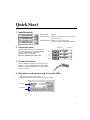
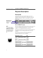
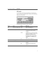
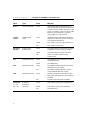
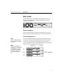
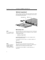
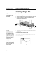
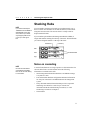
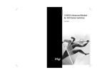
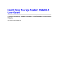
Intel Express
100BASE-T4 Stackable Hub
User Guide
656943-002
First edition
August 1996
Second edition December 1996
Copyright © 1996, Intel Corporation. All rights reserved.
Intel Corporation, 5200 NE Elam Young Parkway, Hillsboro OR 97124-6497
Intel Corporation assumes no responsibility for errors or omissions in this manual. Nor does Intel make any commitment to
update the information contained herein.
* Other product and corporate names may be trademarks of other companies and are used only for explanation and to the
owners’ benefit, without intent to infringe.
ii
Contents
Quick Start
Chapter 1
1
Overview
3
Features ............................................................................................................................................ 3
Physical Description .......................................................................................................................... 4
Chapter 2
Installing the Express Hub
9
Requirements .................................................................................................................................... 9
Installing a Single Hub .................................................................................................................... 10
Stacking Hubs ................................................................................................................................. 11
Removing a Hub from a Stack ......................................................................................................... 12
Installing Uplink Modules ............................................................................................................... 12
Adding a Network Management Module (NMM) ............................................................................ 13
Chapter 3
Connecting the Devices
15
Connecting Cables to the Hub ......................................................................................................... 15
Checking the LEDs ......................................................................................................................... 16
Unit Numbering Convention ........................................................................................................... 18
Partitioned Ports .............................................................................................................................. 18
Using a Switch to Connect Hubs ..................................................................................................... 19
Connecting to Non-100BASE-T4 devices ........................................................................................ 20
Appendix A Fast Ethernet Topology Rules
23
Physical Layer Media Specifications ............................................................................................... 23
Basic Rules ..................................................................................................................................... 24
Network Topology Extensions ......................................................................................................... 26
Appendix B Optional Equipment and Technical Specifications
29
Optional Equipment ........................................................................................................................ 29
Technical Specifications .................................................................................................................. 31
Limited Warranty ........................................................................................................................... 36
iii
C O N T E N T S
Index
Customer Support
iv
Intel Express 100BASE-T4 Stackable Hub
37
Inside back cover
Quick Start
1 Install the hub(s).
Maximum stack:
Six hubs
Rack requirements: Standard 19-in (48.26 cm), 1.5 EIA rack-mount
space for each hub
Shelf requirements: Support for 10 lbs (4.5 kg) per hub
12.3 lbs (5.6 kg) with uplink module and NMM
2 Connect the stack.
Use the cascade cables to connect multiple hubs.
You need to purchase cascade cables separately
from your network services supplier (see
Appendix B for more information).
Do not use UTP cabling to connect hubs.
3 Connect the devices.
Connect 100BASE-T4 devices to the hub using four-pair
Category 3, 4, or 5 unshielded twisted pair (UTP) cabling.
Maximum cable distance between a port and an attached
device is 100 meters.
4 Plug power cords into each hub, then check LEDs.
• Make sure the Pwr LED is lit for all hubs.
• Make sure the numbered port LEDs are lit for connected devices.
Pwr LED
Port LEDs
1
1
Overview
This chapter includes a summary of the Intel Express 100BASE-T4
Stackable Hub’s features and a physical description of the hub and its
components.
Features
Key features of the Intel Express 100BASE-T4 Stackable Hub
•
Compatibility with the IEEE 802.3u standard for Fast Ethernet.
•
Twelve 100BASE-T4 fixed ports.
•
Uplink path to 100BASE-TX or 100BASE-FX devices via optional
uplink modules.
•
Hub management through the optional Network Management
Module (NMM).
•
Support for 4-pair Category 3, 4, or 5 UTP cabling.
3
C H A P T E R
1
Intel Express 100BASE-T4 Stackable Hub
Physical Description
Front panel
The front panel of the Express Stackable Hub provides twelve
100BASE-T4 ports, an LED matrix (see “LED matrix” later in this
chapter for a description of LEDs), a media adapter slot, and an
expansion slot.
Media adapter slot
for uplink modules
Expansion slot
for NMM
RJ-45 100BASE-T4 ports
NOTE
If you include Intel Express
100BASE-TX and 100BASE-T4
Stackable Hubs in the same
stack, make sure you attach
only the appropriate devices
(TX or T4) to each type of
hub.
The twelve 100BASE-T4 ports with fixed RJ-45 connectors allow you
to connect to 100BASE-T4 network devices. You can use 4-pair
Category 3, 4, or 5 unshielded twisted-pair (UTP) cable.
The maximum cable distance between the port and the attached device
is 100 meters (328 feet), including all patch cables, panels, and
connectors.
The following table lists the pinouts and pin pairings for a
100BASE-T4 hub and a server or workstation.
Workstation or server
RJ-45 port
4
Hub
C H A P T E R
1
Overview
LED matrix
The LED matrix on the Express Stackable Hub’s front panel allows
you to view the hub’s operational status, collisions, network utilization,
NMM status, and port status.
The following table describes the LEDs on the matrix.
Label
Type
Pwr
Hub power supply status Green
Stat
Hub status
Color
Meaning
Hub is receiving power.
Off
Hub is not receiving power.
Green
Hub has power, has passed the
confidence test, and is operating
normally.
Amber
At initial power up, indicates the hub is
running its confidence test. If this LED
lights after the confidence test is
performed, the hub is not operating
normally due to a fan failure, a power
supply failure, or a confidence test
failure.
Off
Hub is not receiving power.
RPS
Not supported
N/A
N/A
Col
Collision status
Amber
A collision was detected on the
segment.
Off
Collisions are not detected on the
segment.
5
C H A P T E R
1
Intel Express 100BASE-T4 Stackable Hub
Label
Type
Color
Meaning
Data %
Network utilization
Green
Dynamically indicates the percentage of
network utilization for the Ethernet segment
in a hub or a stack of hubs. Operates as a bar
graph. For example, if the ≤1% and 5% Data
LEDs are green, that stack’s segment is
using roughly 5% of the network.
1 Media
Adapter
Uplink module
status
Green
An uplink module is installed in the media
adapter slot, link status is good, and the port
is not partitioned (disabled).
Amber
Link status is good, but port is partitioned.
Off
Link status is not detected.
Green
The module in the expansion slot passed the
confidence test and is operating normally.
Amber
The module in the expansion slot failed.
Off
There is no module installed in the
expansion slot.
Green
The NMM passed the confidence test and is
operating normally.
Amber
The NMM failed.
Green
The NMM installed in the hub is the master
NMM for that stack of hubs.
Off
The NMM installed in the hub is not the
master NMM for that stack of hubs.
Green
The hub is properly connected to the other
hubs in the stack and is actively managed by
an NMM.
Off
The hub is not managed by an NMM.
Expansion
Slot Stat
Stat
Mstr
Enbl
Expansion slot
module status
Management status
Management status
Management status
Port Status
1 — 12
Port status
(hub ports)
Green
Link status is good; port is not partitioned.
13 — 24
(not used)
Amber
Link status is good; port is partitioned.
Off
No link detected.
6
C H A P T E R
1
Overview
Rear panel
The rear panel of the Express Stackable Hub provides an AC power
receptacle, a redundant power connector (not supported), and two
cascade cable connectors.
Power receptacle
The AC power receptacle is provided for connecting to an AC power
outlet. The Express Stackable Hub accepts between 100 and 240V AC.
Cascade connectors
NOTE
A stack of Express Stackable
Hubs can contain a maximum
of six hubs.
The Cascade Down and Cascade Up connectors and an Intel cascade
cable allow you to stack and link multiple Express Stackable Hubs to
increase the size of a particular workgroup in your network. The
cascade cable connects to the Cascade Down connector on the top hub
and the Cascade Up connector on the hub below it.
NOTE
If you include Intel Express
100BASE-TX and 100BASE-T4
Stackable Hubs in the same
stack, make sure you attach
only the appropriate devices
(TX or T4) to each type of
hub.
7
C H A P T E R
1
Intel Express 100BASE-T4 Stackable Hub
Optional equipment
The Intel 100BASE-T4 Stackable Hub ships with filler panels installed
in the media adapter and expansion slots. Both panels can be removed
to accommodate optional modules.
Media adapter slot
NOTE
Port 1 is disabled when the
media adapter slot is filled.
The media adapter slot is located in the upper-left corner of the Express
100BASE-T4 Stackable Hub and accommodates two types of optional
100 Mbps uplink module:
•
100BASE-TX uplink module
•
100BASE-FX uplink module
Uplink modules allow you to connect to other 100 Mbps network
devices using a different media.
For information about these modules, see “Optional Equipment” in
Appendix B.
Expansion slot
NOTE
The Express 100BASE-T4
Stackable Hub does not
support the 100BASE-TX
12-port expansion module.
8
The expansion slot is located in the lower half of the Express
100BASE-T4 Stackable Hub and accommodates an optional Express
Stackable Hub Network Management Module (NMM).
For information about the NMM, see “Optional Equipment” in
Appendix B.
2
Installing the
Express Hub
Requirements
Rack installation
requirements
Standard 19-in. (48.26 cm.) EIA equipment rack
1.5 EIA rack-mount spaces available for each
hub
Table and shelf
installation requirements
Approximately 13.25-in. (33.66 cm.) by 19.25-in.
(48.90 cm.) area on a level tabletop or shelf
Support for at least 10 lbs. (4.5 kg.) per hub with
filler panels installed in expansion and media
adapter slots
Support for at least 12.3 lbs. (5.6 kg.) per hub
with an NMM and an uplink module installed
Temperature
Ambient temperature between 5° C and 40° C
(41° F and 104° F)
No nearby heat sources such as direct sunlight,
warm air exhausts, or heaters
Humidity
Between 5% and 85%, noncondensing
Ventilation
Minimum 2 in. (5.08 cm.) on all sides for cooling
and adequate airflow in room or wiring closet
Operating conditions
At least 6 ft. (1.83 m.) from nearest source of
electromagnetic noise (such as a photocopier)
Service access
Minimum 12 in. (30.48 cm.) front and rear for
AC disconnect, service access and maintenance
access
Front and rear clearance for cables and wiring
hardware such as punchdown blocks
Wiring hardware
Wiring hardware, such as punchdown blocks or
patch panels, in place before installing the hub
Power
Adequate power source within 6 ft. (1.83 m.)
9
C H A P T E R
2
Intel Express 100BASE-T4 Stackable Hub
Installing a Single Hub
NOTE
To install the hub in a rack
Only qualified technicians
should install and maintain
this equipment.
1
Attach the mounting brackets to the sides of the hub.
2
Align the mounting holes in the brackets with the holes in the rack.
3
Insert two pan-head screws with nylon washers through each
mounting bracket and into the rack.
4
Connect the AC power cord to the hub and then to the wall outlet
or power strip.
CAUTION
The power cord is a North
American type, UL-listed/
CSA-certified power supply
cord. Discard this cord if it’s
inappropriate for the electrical
system of your country, and
get the cord required by your
national electrical codes or
ordinances and certified for
use in your region.
CAUTION
Don’t connect the power cord
to a hub until all hubs are
installed, connected together
through cascade cables, and
ready for operation.
10
To install the hub on a table or shelf
When installing a hub on a table or shelf, place the self-adhesive feet
on the bottom of the hub.
C H A P T E R
2
Installing the Express Hub
Stacking Hubs
NOTE
If you include Intel Express
100BASE-TX and 100BASE-T4
Stackable Hubs in the same
stack, make sure you attach
only the appropriate devices
(TX or T4) to each type of
hub.
You can install a maximum of six hubs in an equipment rack or on a
shelf or a table. Once the hubs are stacked and secured, connect them
using Intel cascade cables. The cascade cable is a unique cable for
Express Stackable Hubs.
If you install an optional Network Management Module (NMM), it
assigns unit numbers starting from the top of the stack. Position the hub
you want to designate number 1 at the top of the stack.
Notes on cascading
NOTE
Use Intel cascade cables to
connect Express Stackable
Hubs. Do not use UTP cabling
to connect hubs.
A stack of hubs functions as a single repeater or collision domain. The
cascade cables form a cascade bus that carries the following
information to each hub in the stack:
•
Stack management information that allows one NMM to manage
every hub in a stack.
•
Port statistics that distribute configuration and status information
for each port in the stack to an NMM and network management
system.
•
Daisy chain unit number information that provides a sequential
numbering convention for a stack of up to six hubs. For
information about the unit numbering convention, see “Unit
Numbering Convention” in Chapter 3.
•
Network data.
11
C H A P T E R
2
Intel Express 100BASE-T4 Stackable Hub
Removing a Hub from a Stack
To remove the hub from a rack
CAUTION
When you remove a hub from
the middle of the stack (any
hub located between two
operating hubs) and don’t
reattach the cascade cables,
you split the Ethernet segment
into two separate segments.
CAUTION
Check that the screw locks on
the cable connectors are fully
tightened and the cable connection is secure. A faulty
cable connection could disrupt the operation of the
entire stack.
1
Disconnect power to the hub by unplugging the power cable.
2
Disconnect the appropriate cascade cables.
3
Use a #2 Phillips screwdriver to loosen the screws that secure each
mounting bracket to the rack.
4
Remove the screws from the mounting bracket while supporting
the bottom of the hub, then carefully remove the hub from the rack.
To remove the hub from a stack that is mounted on a table
or shelf
Gently lift any hubs stacked on top of the hub you want to remove, then
carefully remove that hub from the stack.
After you’ve removed the hub from the stack, connect the free end of
the cascade cable connected to the Cascade Down connector on the top
hub to the Cascade Up connector on the bottom hub.
Installing Uplink Modules
NOTE
When you install an uplink
module in the hub’s media
adapter slot, port 1 is disabled.
You can install an optional 100BASE-TX or 100BASE-FX uplink
module in the media adapter slot. Install these modules before
connecting power to the hub. If you install these modules when the hub
is powered, the hub may reset, temporarily suspending port
connectivity in the hub.
For more information on installing uplink modules, see the
documentation that ships with the modules.
12
C H A P T E R
2
Installing the Express Hub
Adding a Network
Management Module (NMM)
After powering down the hub, install the NMM in the hub at the top of
your stack. When an NMM is installed in the stack, it automatically
numbers the hubs in the stack. After you install the NMM and
reconnect the power cord, the entire stack of hubs resets, and you
temporarily lose port connectivity to each hub.
For more information on installing the NMM, see the Express
Stackable Hub Network Management Module User Guide.
13
3
Connecting the
Devices
Connecting Cables to the Hub
NOTE
Make sure your network
conforms to the Fast Ethernet
rules described in Appendix A.
Connect devices directly to ports on the Express 100BASE-T4
Stackable Hub or to ports on installed uplink modules. This illustration
shows how to connect a UTP cable to an RJ-45 connector and a fiber
optic cable to an SC connector.
NOTE
100BASE-T4 devices use
4-pair Category 3, 4, or 5 UTP
cabling. 100BASE-TX devices
use 2-pair Category 5 UTP
cabling.
If your stack combines Intel Express 100BASE-TX and 100BASE-T4
Stackable Hubs, make sure you attach the appropriate device (TX or
T4) to each type of hub. If you attach the wrong type of device to a
hub, that device won’t function properly, and the hub may malfunction.
15
C H A P T E R
3
Intel Express 100BASE-T4 Stackable Hub
You can connect the following 100 Mbps devices to the ports on the
Express Stackable Hub and optional uplink modules:
•
Workstations
•
Servers
•
Printers
•
Transceivers
•
Switching hubs
•
Routers
•
Printers
•
Print servers
See “Using a switch to connect hubs” later in this chapter for
information about connecting to 100 Mbps switching hubs. For
information about making connections to other 100BASE-T4 devices,
refer to the documentation that shipped with the device.
Checking the LEDs
When you connect the power cord to the Express 100BASE-T4
Stackable Hub, the hub performs a confidence test. During this test, the
hub’s Stat LED lights amber to indicate the test is in progress.
When the confidence test successfully completes, the LEDs on the
hub’s front panel should appear as follows:
16
•
The Pwr LED lights green, indicating the hub is receiving power.
•
The Stat LED lights green, indicating the hub passed the
confidence test and is operating normally.
C H A P T E R
3
Connecting the Devices
•
The Data % LEDs light green on each hub, indicating the overall
network utilization percentage of the Ethernet segment. Because a
stack of hubs is a single segment, utilization is the same for each
hub in the stack.
•
If an optional uplink module is installed in the media adapter slot,
the appropriate cable is connected to the media adapter port, and
the link status is good, the Media Adapter LED lights green. When
this LED is on, port 1 on the hub is disabled.
•
If an NMM is installed in the expansion slot, the Enbl LEDs on
each hub in the stack light green, indicating the hub is properly
connected to the other hubs in the stack and is actively managed by
an NMM.
•
If an NMM is installed in the expansion slot, the Management
LEDs light as follows:
– The Stat LED lights green, indicating the NMM passed the
confidence test and is operating normally.
– The Mstr LED lights green, indicating the NMM is the master
NMM in the stack.
•
A Port Status LED for each port on the hub provides port status.
LED
Color
Status indications
Hub ports 1–12
Green
Link is good, port is not
partitioned (disabled).
Amber
Link is good, port is
partitioned.
Off
Link is not detected.
17
C H A P T E R
3
Intel Express 100BASE-T4 Stackable Hub
Unit Numbering Convention
NOTE
A stack of Express Stackable
Hubs can contain a maximum
of six hubs.
When Express Hubs are stacked, cascaded, and powered, they are
assigned “unit” numbers that are stored in the hub’s nonvolatile
memory. Hub numbers are assigned according to a hub’s physical
location in the stack. The NMM assigns numbers from the top down—
the hub at the top of the stack is numbered 1, the hub below hub 1 is
numbered 2, and so on.
In a fully equipped stack, hubs are assigned numbers 1 through 6. You
can identify the unit numbers of the hubs in the stack using network
management software such as Intel LANDesk® Network Manager.
As you build your stack to include more hubs, each hub you add is
assigned a unit number according to its position in the stack after the
NMM is reset or the stack is renumbered through network management
software.
Partitioned Ports
When the Express Stackable Hub detects a large number of consecutive
collisions on a port, it automatically disables, or partitions, that port.
These collisions often occur due to excessive traffic or a
malfunctioning port or network adapter. After the problem is corrected,
the port is automatically re-enabled.
18
C H A P T E R
3
Connecting the Devices
Using a Switch to Connect
Hubs
Integrating switching into the network enables network segmentation,
which increases the total capacity and performance. You can add 100
Mbps workgroups to the network and connect them to individual ports
on a Fast Ethernet switch.
The illustration below shows how Express Stackable Hubs interface
with a switching hub to increase the total capacity and performance of
an entire network.
Three groups of 100 Mbps workstations are connected to three separate
hub stacks. The Express Hubs are stacked to provide multiple ports per
stack. This network shows three hub stacks that support individual
workgroups.
A 100BASE-FX uplink module is installed in one of the Express Hubs,
connecting the hub stack to the switching hub through a 100 Mbps
fiber link. Two servers equipped with 100 Mbps LAN adapters are
connected to the switch to provide centralized services to workstations
in all three workgroups.
19
C H A P T E R
3
Intel Express 100BASE-T4 Stackable Hub
Connecting to Non100BASE-T4 devices
Connecting to 100BASE-TX devices
You have two options for connecting the Express 100BASE-T4
Stackable Hub to a 100BASE-TX device:
•
an Intel 100BASE-TX Uplink Module
•
a routing server equipped with a 100BASE-T4 NIC and a
100BASE-TX NIC
You can also use Intel cascade cables to combine Express
100BASE-TX Stackable Hubs with Express 100BASE-T4 Stackable
hubs in a stack. If you’re using a combined stack, make sure you attach
the appropriate device (TX or T4) to each type of hub. If you attach the
wrong type of device to a hub, that device won’t function properly, and
the hub may malfunction.
100BASE-TX Uplink Module
NOTE
Port 1 on a hub is disabled
when an uplink module is
installed.
Intel’s 100BASE-TX Uplink Module fits in the hub’s media adapter
slot and allows you to connect to 100BASE-TX devices using
Category 5 UTP cabling.
For more information on the 100BASE-TX Uplink Module, see
Appendix B.
20
C H A P T E R
3
Connecting the Devices
Routing server
If you’re using a NOS that supports multi-protocol routing, such as
Novell NetWare* or Windows NT*, an inexpensive way to connect the
100BASE-T4 and 100BASE-TX segments is to install both a
100BASE-T4 and 100BASE-TX LAN adapter in your server and let
the server bridge the segments.
Connecting to 100BASE-FX devices
NOTE
Port 1 on a hub is disabled
when an uplink module is
installed.
To connect the Express 100BASE-T4 Stackable Hub to a
100BASE-FX device, use an Intel 100BASE-FX Uplink Module. The
100BASE-FX Uplink Module fits in the hub’s media adapter slot and
allows you to connect to 100BASE-FX devices.
For more information on the 100BASE-FX Uplink Module, see
Appendix B.
Connecting to 10BASE-T devices
NOTE
You cannot connect a
10BASE-T device directly to
the Express Stackable Hub.
You have three options for connecting the Express 100BASE-T4
Stackable Hub to 10BASE-T devices:
•
a 100BASE-TX Uplink Module and an Express 10/100 Downlink.
•
a 100BASE-TX Uplink Module and a 10/100 switching hub.
•
a routing server equipped with a 100BASE-T4 NIC and a
10BASE-T NIC.
21
C H A P T E R
3
Intel Express 100BASE-T4 Stackable Hub
100BASE-TX Uplink Module and 10/100 Downlink
NOTE
Port 1 on a hub is disabled
when an uplink module is
installed.
Intel’s 100BASE-TX Uplink Module fits in the hub’s media adapter
slot and allows you to connect to 100BASE-TX devices, such as the
Express 10/100 Downlink. The Express 10/100 Downlink allows you
to connect to 10BASE-T devices.
100BASE-TX Uplink Module and 10/100 switching
hub
You can also use the 100BASE-TX Uplink Module to connect to a
10/100 switching hub. The switching hub then bridges the 10 Mbps and
100 Mbps segments
Routing server
If you’re using a NOS that supports multi-protocol routing, such as
Novell NetWare or Windows NT, you can use a routing server
equipped with a 100BASE-T4 NIC and a 10BASE-T NIC to bridge the
100BASE-T4 and 10BASE-T segments.
22
A
Fast Ethernet
Topology Rules
This appendix describes
•
100BASE-T physical layer media specifications
•
repeater rules
For a complete explanation of the set of 100BASE-T rules and
guidelines, refer to the Institute of Electrical and Electronics
Engineers (IEEE) 100BASE-T 802.3u standard.
For information about cables for Ethernet networks, refer to the
Electronic Industries Association/Telecommunications Industry
Association (EIA/TIA) wiring standard EIA/TIA 568.
Physical Layer Media
Specifications
Three media specifications are associated with 100BASE-T:
•
100BASE-TX
•
100BASE-FX
•
100BASE-T4
The following table lists the cable and connector types and the coding
scheme that each media specification uses.
23
A P P E N D I X
A
Intel Express 100BASE-T4 Stackable Hub
Media
specification
Cable
type(s)
Connector
type(s)
Coding
scheme
100BASE-T4
CAT 3, 4, 5 UTP
(4-pair wire)
RJ-45
8B/6T
100BASE-TX
CAT 5 UTP
(2-pair wire)
RJ-45
4B/5B
100BASE-FX
62.5/125 micron
SC
fiber optic cable
(2 multi-mode fibers)
4B/5B
Basic Rules
When deploying 100BASE-T4 Fast Ethernet, you should follow three
basic rules:
•
UTP cable length from repeater to workstation or switch can’t
exceed 100 meters (328 feet).
•
Fiber cable length from repeater to workstation or switch can’t
exceed 131 meters (429 feet) .
•
You can’t use UTP cabling to connect Express Stackable Hubs to
each other. Express Stackable Hubs are Class I repeaters and can
be connected only with Intel Cascade Cables.
Distance limitations
100BASE-T4 and 100BASE-TX
The EIA/TIA 568 wiring standard specifies that UTP wiring must not
exceed 100 meters (328 feet) from repeater to workstation or switch.
This specification limits collision domain diameter to 200 meters (656
meters).
100BASE-T4 and 100BASE-FX
In a 100BASE-T4/100BASE-FX environment, the collision domain
must not exceed 231 meters (757 feet)—100 meters T4 and 131
meters FX—in diameter.
24
A P P E N D I X
A
Fast Ethernet Topology Rules
Repeater rules
The 100BASE-T standard defines two types of repeaters — Class I
and Class II. The Express Stackable Hub is a Class I repeater. Class I
repeaters (sometimes called translational repeaters) limit the number
of repeaters in a physical domain to one.
However, the one-repeater maximum for Class I repeaters does not
limit the port density of 100BASE-T networks when stackable hubs
are used. Express Stackable Hubs can be stacked to form a single,
multi-port repeater where each repeater stack can be managed like a
single repeater unit.
Class I repeaters cannot be daisy-chained (connected to one another
using UTP cabling).
25
A P P E N D I X
A
Intel Express 100BASE-T4 Stackable Hub
Network Topology Extensions
You can extend the network topology by connecting Express
Stackable Hubs to a switching hub.
In the illustration below, the network topology is extended to a
maximum of 400 meters (1312 feet). In this network, a switching hub
interconnects two separate repeater stacks to form two separate
collision domains. Since each UTP cable, from workstation to
repeater and repeater to switch, does not exceed 100 meters (328
feet), the collision domains do not exceed 200 meters (656 feet) in
diameter. Integrating the switch into the network to form two collision
domains of 200 meters each extends the network topology to 400
meters.
26
A P P E N D I X
A
Fast Ethernet Topology Rules
In the next illustration, the network topology is extended to a
maximum distance of 491 meters (1610 feet). In this network, a 160
meter (524 feet) fiber link connects the 100BASE-TX repeater to the
switch, and a 131 meter (429 feet) fiber link connects the 100BASET4 repeater to the switch. 100 meter (328 feet) Category 5 UTP
wiring connects workstations and servers to the repeater stacks. The
100BASE-TX collision domain is 260 meters (852 feet), and the
100BASE-T4 collision domain is 231 meters (757 feet). When the
two collision domains are interconnected through the switch, the
network topology is extended to a total of 491 meters.
If you’re using a 100BASE-FX Uplink Module in a 100BASE-T4
stackable hub, fiber cable length is limited to 131 meters. If you’re
using a 100BASE-FX Uplink Module in a 100BASE-TX stackable
hub, fiber cable length is limited to 160 meters. If a stack combines
100BASE-TX hubs and 100BASE T4 hubs, fiber distance is limited to
131 meters.
27
A P P E N D I X
A
Intel Express 100BASE-T4 Stackable Hub
You can extend the 100BASE-T network topology further by
interconnecting the switches using fiber links. Interconnecting two
switches creates a network that contains four separate collision
domains. The overall network topology grows while each collision
domain can be modeled after the extended collision domains shown in
the previous two illustrations.
The next illustration shows how two separate 100BASE-T networks,
each supporting different workgroups in different physical locations,
are interconnected using a 2-km fiber link.
28
B
Optional Equipment
and Technical
Specifications
This appendix describes optional equipment supported by the Express
100BASE-T4 Stackable Hub and provides technical specifications for
the hub.
Optional Equipment
Uplink modules
The 100BASE-TX and 100BASE-FX uplink modules fit into the media
adapter slot and provide a connection to other 100 Mbps equipment in
your network.
The Intel 100BASE-TX Uplink Module (Intel product code
EC100MATX) provides a standard RJ-45 connector for Category 5
UTP cable. The maximum distance between the port and the attached
100BASE-TX device is 100 meters (including all patch cables, panels,
and connectors).
The Intel 100BASE-FX Uplink Module (Intel product code
EC100MAFX) provides a standard SC connector for 62.5/125 µm
multimode fiber optic cable. The maximum distance between the
uplink port and the attached 100BASE-FX device is 131 meters
(including all patch cables, panels, and connectors).
29
A P P E N D I X
B
Intel Express 100BASE-T4 Stackable Hub
Network Management Module (NMM)
The Intel Express Stackable Hub Network Management Module (Intel
product code EC100NMM) fits into the expansion slot and allows you
to extend per-port advanced Simple Network Management Protocol
(SNMP) management functions to each Express Stackable Hub in the
stack.
Advanced SNMP management allows you to communicate with
SNMP-compatible software to
•
monitor network statistics and view errors and hardware status.
•
view configuration and status information for each port in a stack
of up to six hubs.
•
gather network communications and activities information for
analysis and storage.
The advanced level of network management also supports Intel
LANDesk Network Manager. The NMM agent software contains
embedded management features that allow you to get important
information from existing nodes.
Cascade cables
Intel cascade cables (Intel product code EC100CC) allow you to stack
and link multiple Express Stackable Hubs so you can expand port
connections in a network segment. A stack can contain a maximum of
six hubs. When connected using Intel cascade cables, the entire stack of
hubs acts as a single repeater or collision domain.
30
A P P E N D I X
B
Optional Equipment and Technical Specifications
Technical Specifications
Network Protocol and Standards Compatibility
IEEE 802.3u 100BASE-T
Data Rate
T4: 100 Mbps with 8B/6T coding scheme
TX: 100 Mbps with 4B/5B coding scheme
FX: 100 Mbps with 4B/5B coding scheme
Electrical Specifications
Input power:
Thermal rating:
AC line frequency:
Input voltage (rms):
Volt amperes rating:
160 W
550 BTU/hr
47–63 Hz
90–264 V AC
250 VA
Physical Specifications
Dimensions: 11.18 (l) by 17.25 (w) by 2.57 (h) in.
28.40 (l) by 43.82 (w) by 6.53 (h) cm.
Weight:
10.0 lbs (4.5 kg) with filler panels installed
12.3 lbs (5.6 kg) with an NMM and a media adapter
installed (optional equipment)
Environmental Specifications
Operating temperature:
5° to 40° C
Storage temperature:
–25° to 70° C
Operating humidity:
85% maximum relative humidity,
noncondensing
Storage humidity:
95% maximum relative humidity,
noncondensing
Operating altitude:
10,000 ft (3,000 m) maximum
Storage altitude:
10,000 ft (3,000 m) maximum
31
A P P E N D I X
B
Intel Express 100BASE-T4 Stackable Hub
Safety Agency Approvals
UL listed (UL 1950) Third Edition
UL listed for Canada
TUV certified to IEC 950 Second Edition plus A1/A2 and EN60950
A1/A2
Repeater Type
I
Class I repeater
Interface Options
RJ-45 connectors for 4-pair Category 3, 4, or 5 UTP
100BASE-T4 Ethernet interface
RJ-45 connectors for 2-pair Category 5 UTP 100BASE-TX Ethernet
interface with installed 100BASE-TX uplink module
Fiber optic SC connectors for 100BASE-FX Ethernet interface with
installed 100BASE-FX uplink module
Notice
For 120-volt operation, use only with power cord having a parallel
blade, grounding type attachment plug, rated 10 amp, 125 volts.
For 240-volt operation, use only with power cord having a tandem
blade, grounding type attachment plug, rated 10 amp, 250 volts.
32
A P P E N D I X
B
Optional Equipment and Technical Specifications
Statement of Conditions
In the interest of improving internal design, operational function, or reliability, Intel Corp. reserves the right to make changes to
the products described in this document without notice.
Intel Corp. does not assume any liability that may occur due to the use or application of the products or circuit layouts described
herein.
Electromagnetic Emissions
Meets requirements of FCC Part 15, Subpart B, Class A, EN 55 022 (CISPR 22:1985), Class A, and VCCI Class 1 ITE
Electromagnetic Susceptibility
Electrostatic discharge (ESD): IEC 801-2, Electromagnetic susceptibility: IEC 801-3, Electrical fast transient/burst: IEC 801-4
Federal Communications Commission (FCC) Statement
Note: This equipment has been tested and found to comply with the limits for a Class A digital device, pursuant to Part 15 of the
FCC rules. These limits are designed to provide reasonable protection against harmful interference when the equipment is
operated in a commercial environment. This equipment generates, uses, and can radiate radio frequency energy. If it is not
installed and used in accordance with the instruction manual, it may cause harmful interference to radio communications.
Operation of this equipment in a residential area is likely to cause harmful interference, in which case users will be required to
take whatever measures may be necessary to correct the interference at their own expense.
Manufacturer Declaration
We certify that this product is in compliance with EU directive 89/336/EEC, using the EMC standards EN55022 and
EN50082-1. This product also meets or exceeds EN60950 safety requirements.
This product has been tested and verified to meet CISPR 22 Class A requirements.
Voluntary Control Council for Interference (VCCI) Statement
This equipment is in the Class 1 category (information equipment to be used in commercial and/or industrial areas) and conforms
to the standards set by the Voluntary Control Council for Interference by Data Processing Equipment and Electronic Office
Machines that are aimed at preventing radio interference in commercial and/or industrial areas.
Consequently, when this equipment is used in a residential area or in an adjacent area thereto, radio interference may be caused
to equipment such as radios and TV receivers.
Compliance with the applicable regulations is dependent upon the use of shielded cables. The user is responsible for procuring
the appropriate cables. Read instructions for correct handling.
WARNING
This is a Class A product. In a domestic environment this product may cause radio interference in which case the user may be
required to take adequate measures.
33
A P P E N D I X
B
Intel Express 100BASE-T4 Stackable Hub
WARNING
The system is designed to operate in a typical office environment. Choose a site that is:
·
Clean and free of airborne particles (other than normal room dust).
·
Well ventilated and away from sources of heat including direct sunlight.
·
Away from sources of vibration or physical shock.
·
Isolated from strong electromagnetic fields produced by electrical devices.
·
In regions that are susceptible to electrical storms, we recommend you plug your system into a surge suppressor and
disconnect telecommunication lines to your modem during an electrical storm.
·
Provided with a properly grounded wall outlet.
Do not attempt to modify or use the supplied AC power cord if it is not the exact type required.
Ensure that the system is disconnected from its power source and from all telecommunications links, networks, or modems lines
whenever the chassis cover is to be removed. Do not operate the system with the cover removed.
AVERTISSEMENT
Le système a été conçu pour fonctionner dans un cadre de travail normal. L’emplacement choisi doit être:
·
Propre et dépourvu de poussière en suspension (sauf la poussière normale).
·
Bien aéré et loin des sources de chaleur, y compris du soleil direct.
·
A l’abri des chocs et des sources de ibrations.
·
Isolé de forts champs magnétiques géenérés par des appareils électriques.
·
Dans les régions sujettes aux orages magnétiques il est recomandé de brancher votre système à un supresseur de surtension,
et de débrancher toutes les lignes de télécommunications de votre modem durant un orage.
·
Muni d’une prise murale correctement mise à la terre.
Ne pas utiliser ni modifier le câble d’alimentation C. A. fourni, s’il ne correspond pas exactement au type requis.
Assurez vous que le système soit débranché de son alimentation ainsi que de toutes les liaisons de télécomunication, des réseaux,
et des lignes de modem avant d’enlever le capot. Ne pas utiliser le système quand le capot est enlevé.
WARNUNG
Das System wurde für den Betrieb in einer normalen Büroumgebung entwickelt. Der entwickelt. Der Standort sollte:
·
sauber und staubfrei sein (Hausstaub ausgenommen);
·
gut gelüftet und keinen Heizquellen ausgesetzt sein (einschließlich direkter Sonneneinstrahlung);
·
keinen Erschütterungen ausgesetzt sein;
·
keine starken, von elektrischen Geräten erzeugten elektromagnetischen Felder aufweisen;
·
in Regionen, in denen elektrische Stürme auftreten, mit einem Überspannungsschutzgerät verbunden sein; während eines
elektrischen Sturms sollte keine Verbindung der Telekommunikationsleitungen mit dem Modem bestehen;
·
mit einer geerdeten Wechselstromsteckdose ausgerüstet sein.
Versuchen Sie nicht, das mitgelieferte Netzkabel zu ändern oder zu verwenden, wenn es sich nicht um genau den erforderlichen
Typ handelt.
Das System darf weder an eine Stromquelle angeschlossen sein noch eine Verbindung mit einer
Telekommunikationseinrichtung, einem Netzwerk oder einer Modem-Leitung haben, wenn die Gehäuseabdeckung entfernt wird.
Nehmen Sie das System nicht ohne die Abdeckung in Betrieb.
34
A P P E N D I X
B
Optional Equipment and Technical Specifications
AVVERTENZA
Il sistema è progettato per funzionare in un ambiente di lavoro tipico. Scegliere una postazione che sia:
·
·
·
·
·
·
Pulita e libera da particelle in sospensione (a parte la normale polvere presente nell’ambiente).
Ben ventilata e lontana da fonti di calore, compresa la luce solare diretta.
Al riparo da urti e lontana da fonti divibrazione.
Isolata dai forti campi magnetici prodotti da dispositivi elettrici.
In aree soggette a temporali, è consigliabile collegare il sistema ad un limitatore di corrente. In caso di temporali, scollegare
le linee di comunicazione dal modem.
Dotata di una presa a muro correttamente installata.
Non modificare o utilizzare il cavo di alimentazione in c. a. fornito dal produttore, se non corrisponde esattamente al tipo
richiesto.
Prima di rimuovere il coperchio del telaio, assicurarsi che il sistema sia scollegato dall’alimentazione, da tutti i collegamenti di
comunicazione, reti o linee di modem. Non avviare il sistema senza aver prima messo a posto il coperchio.
ADVERTENCIAS
El sistema está diseñado para funcionar en un entorno de trabajo normal. Escoja un lugar:
·
·
·
·
·
·
Limpio y libre de partículas en suspensión (salvo el polvo normal)
Bien ventilado y alejado de fuentes de calor, incluida la luz solar directa.
Alejado de fuentes de vibración.
Aislado de campos electromagnéticos fuertes producidos por dispositivos eléctricos.
En regiones con frecuentes tormentas eléctricas, se recomienda conectar su sistema a un eliminador de sobrevoltage y
desconectar el módem de las líneas de telecomunicación durante las tormentas.
Previsto de una toma de tierra correctamente instalada.
No intente modificar ni usar el cable de alimentación de corriente alterna, si no se corresponde exactamente con el tipo
requerido.
Asegúrese de que cada vez que se quite la cubierta del chasis, el sistema haya sido desconectado de la red de alimentación y de
todos lo enlaces de telecomunicaciones, de red y de líneas de módem. No ponga en funcionamiento el sistema mientras la
cubierta esté quitada.
35
A P P E N D I X
B
Intel Express 100BASE-T4 Stackable Hub
Limited Warranty
Intel warrants to the original owner that the product delivered in this package will be free from defects in material and workmanship for three (3)
years following the latter of: (i) the date of purchase only if you register by returning the registration card as indicated thereon with proof of
purchase; or (ii) the date of manufacture; or (iii) the registration date if by electronic means provided such registration occurs within 30 days from
purchase. This warranty does not cover the product if it is damaged in the process of being installed. Intel recommends that you have the company
from whom you purchased this product install the product.
INTEL RESERVES THE RIGHT TO FILL YOUR ORDER WITH A PRODUCT CONTAINING NEW OR REMANUFACTURED
COMPONENTS. THE ABOVE WARRANTY IS IN LIEU OF ANY OTHER WARRANTY, WHETHER EXPRESS, IMPLIED OR
STATUTORY, INCLUDING, BUT NOT LIMITED TO, ANY WARRANTY OF MERCHANTABILITY, FITNESS FOR A PARTICULAR
PURPOSE, OR ANY WARRANTY ARISING OUT OF ANY PROPOSAL, SPECIFICATION OR SAMPLE.
This warranty does not cover replacement of products damaged by abuse, accident, misuse, neglect, alteration, repair, disaster, improper
installation or improper testing. If the product is found to be otherwise defective, Intel, at its option, will replace or repair the product at no charge
except as set forth below, provided that you deliver the product along with a return material authorization (RMA) number either to the company
from whom you purchased it or to Intel (North America only). If you ship the product, you must assume the risk of damage or loss in transit. You
must use the original container (or the equivalent) and pay the shipping charge. Intel may replace or repair the product with either new or
remanufactured product or parts, and the returned product becomes Intel’s property. Intel warrants the repaired or replaced product to be free from
defects in material and workmanship for a period of the greater of: (i) ninety (90) days from the return shipping date; or (ii) the period of time
remaining on the original three (3) year warranty.
This warranty gives you specific legal rights and you may have other rights which vary from state to state. All parts or components contained in
this product are covered by Intel’s limited warranty for this product.
Copyright © 1996 by Intel Corporation. All rights reserved. This document may not be reproduced in whole or in part without the express written
permission of Intel Corporation.
Intel Corporation, 5200 NE Elam Young Parkway, Hillsboro OR 97124
Returning a defective product
From North America:
Before returning any product, contact Intel Customer Support and obtain a Return Material Authorization (RMA) number by calling +1 503 2647000.
If the Customer Support Group verifies that the product is defective, they will have the RMA department issue you an RMA number to place on
the outer package of the product. Intel cannot accept any product without an RMA number on the package.
All other locations:
Return the product to the place of purchase for a refund or replacement.
Limitation of liability and remedies
INTEL SHALL HAVE NO LIABILITY FOR ANY INDIRECT, SPECULATIVE, CONSEQUENTIAL, INCIDENTAL, PUNITIVE OR
SPECIAL DAMAGES ARISING FROM THE USE OF OR INABILITY TO USE THIS PRODUCT INCLUDING, WITHOUT LIMITATION,
LOSS OF USE, BUSINESS INTERRUPTIONS, LOSS OF PROFITS, AND LOSS OF GOODWILL, WHETHER ANY SUCH DAMAGES
ARISE OUT OF CONTRACT NEGLIGENCE, TORT, OR UNDER ANY WARRANTY, IRRESPECTIVE OF WHETHER INTEL HAS
ADVANCE NOTICE OF THE POSSIBILITY OF ANY SUCH DAMAGES. NOTWITHSTANDING THE FOREGOING, INTEL’S TOTAL
LIABILITY FOR ALL CLAIMS UNDER THIS AGREEMENT SHALL NOT EXCEED THE PRICE PAID FOR THE PRODUCT. THESE
LIMITATIONS ON POTENTIAL LIABILITIES WERE AN ESSENTIAL ELEMENT IN SETTING THE PRODUCT PRICE. INTEL NEITHER
ASSUMES NOR AUTHORIZES ANYONE TO ASSUME FOR IT ANY OTHER LIABILITIES.
Some states do not allow the exclusion or limitation of incidental or consequential damages, so the above limitations may not apply to you.
Software provided with the hardware product is not covered under the hardware warranty described above. See the applicable software license
agreement which shipped with the product for details on any software warranty.
April 1996
36
I
Index
1 Media Adapter LED
operating conditions 6
verifying installation 17
100BASE-FX
data rate 31
devices, connecting to 21
distance limitations 24, 27
media specification 24
uplink module 29
100BASE-FX Uplink Module
installation guidelines 12
using 21
100BASE-T
network topology extensions 26
switched LAN 19
100BASE-T4
data rate 31
distance limitations 24, 26
media specification 24
100BASE-T4 ports
connecting cables 15
100BASE-TX
data rate 31
devices, connecting to 20
media specification 24
uplink module 29
100BASE-TX Uplink Module
installation guidelines 12
using 20, 21
10BASE-T
devices, connecting to 21
A–C
AC line frequency 31
AC power receptacle
description 7
location 7
Altitude
operating and storage 31
Approvals
safety agency 32
Cables
connecting 15
length 24
Cascade cables
installation considerations 11
order codes 30
Cascade connectors 7
Class 1 repeaters 32
Class 2 repeaters 25
37
I
N
D
E
X
Intel Express 100BASE-T4 Stackable Hub
Coding schemes
media specifications 24
Col LED
operating conditions 5
Confidence test 16
Connecting
cables 15
to 100BASE-FX devices 21
to 100BASE-TX devices 20
to 10BASE-T devices 21
to non-100BASE-T4 devices 20
Connecting hubs
using a switch 19
using cascade cables 11
D–F
Data % (utilization) LED
operating conditions 6
verifying installation 17
Data rate
100BASE-FX 31
100BASE-T4 31
100BASE-TX 31
Dimensions, physical 31
Distance limitations
collision domain 24
fiber 24
UTP 24
EIA/TIA 568 wiring standard 23
Electrical specifications
AC line frequency 31
input power specification 31
input voltage 31
thermal rating 31
volt amperes rating 31
Electromagnetic emissions 33
Electromagnetic susceptibility 33
Enbl LED
operating conditions 6
verifying installation 17
Environmental specifications 31
38
Ethernet segment
collision domain 26, 27
network utilization status 6, 17
Expansion slot 8
Expansion Slot Stat LED
operating conditions 6
Express 10/100 Downlink
connecting to 21
Fast Ethernet
basic rules 24
Features 3
Front panel features
Expansion slot 4
LED matrix 5
Media adapter slot 4
RJ-45 connectors 4
H–L
Humidity
operating and storage 31
IEEE 100BASE-T 802.3u standard 23, 31
Input power specification 31
Input voltage (rms) specification 31
Installing
cascade cables 11
hubs
in a rack 10
on a table or shelf 10
mounting brackets 10
NMM 13
uplink modules 12
Interface options 32
LEDs
1 Media Adapter 6, 17
checking 16
Col 5
Data % (utilization) 6, 17
Enbl 6, 17
Expansion Slot Stat 6
Management Mstr 17
Management Stat 6, 17
I
N
D
E
X
Intel Express 100BASE-T4 Stackable Hub
matrix 4
Mstr 6
Port Status 6, 17
Pwr 5, 16
Stat 5, 16
Length
cables 24
collision domain 24
M–O
Management module
description 30
installing 13
numbering convention 11
Management Mstr LED
operating conditions 6
verifying installation 17
Management Stat LED
operating conditions 6
verifying installation 17
Media Adapter LED
operating conditions 6
verifying installation 17
Media adapter slot 8
Media specification coding schemes 24
Mounting brackets
installing 10
removing 12
NMM (Network Management Module)
description 30
installing 13
unit numbering convention 11
Non-100BASE-T4 devices
connecting to 100BASE-FX 21
connecting to 100BASE-TX 20
connecting to 10BASE-T 21
Numbering convention 18
Operating conditions 9
Optional equipment
cascade cables 30
NMM 30
uplink modules 29
P– S
Panel
front 4
rear 7
Partitioned ports 18
Physical layer media specifications
Physical specifications
dimensions 31
weight 31
Port Status LEDs
operating conditions 6
verifying installation 17
Power cord restrictions 10
Power receptacle 7
Pwr LED
operating conditions 5
verifying installation 16
Quick start 1
Rear panel features
AC power receptacle 7
Cascade Down connector 7
Cascade Up connector 7
Removing
hubs
from a rack 12
from a shelf or table 12
mounting brackets 12
Repeater rules 25
Requirements
cable length (maximum) 24
humidity 9
rack installation 9
table and shelf installation 9
temperature 9
ventilation 9
23
39
I
N
D
E
X
Intel Express 100BASE-T4 Stackable Hub
Restrictions, power cords 10
RJ-45 connectors
connecting cable 15
hub front panel 4
interface options 32
media specification parameters 24
pin pairings 4
pinouts 4
Rules
cable length 24
distance limitations 24
repeater 25
Safety agency approvals 32
SC connectors 15, 24, 32
Service access 9
SNMP 30
Specifications
physical layer media 23
Stacking
100BASE-T4 and 100BASE-TX hubs
100BASE-T4 hubs 11
100BASE-TX and 100BASE-T4 hubs
numbering convention 18
Standards
IEEE 100BASE-T 802.3u 23
Stat LED
operating conditions 5
verifying installation 16
T–W
Technical specifications 31
Temperature
requirements 31
Thermal rating 31
Topology rules
Fast Ethernet 23
Uplink modules
100BASE-FX 8
100BASE-TX 8
UTP requirements 24
Volt amperes rating 31
40
Weight 31
Wiring hardware 9
Wiring standard
EIA/TIA 568 23
Workgroups, 100 Mbps
15
20
19
Intel Automated Customer Support
You can reach Intel’s automated support services 24 hours a day, every day at no charge. The services contain
the most up-to-date information about Intel products. You can access installation instructions, troubleshooting information, and general product information.
World Wide Web & Internet FTP
Access Intel’s World Wide Web home page
or download information using
anonymous FTP.
Troubleshooting
✓
Software updates
✓
Installation notes
✓
Product information
✓
How to access:
WWW
News: news://cs.intel.com
Customer Support: http://www-cs.intel.com
FTP
Host: ftp.intel.com
Directory: /support
Intel BBS
Use Intel’s Bulletin Board. Dial in by
modem at 8-N-1, and up to 14.4 Kbps.
✓
US and Canada
Europe
Worldwide
1-503-264-7999
+44-1793-432955
+1-503-264-7999
Intel Customer Support Technicians
Free support for 90 days: You can speak with our technical support professionals free of charge for 90 days
after your initial call.
Other support services: You can purchase a range of support services, including 24 hour support, per incident
support, on-site service, and software and hardware maintenance agreements. For details about the Intel
Support Service options, download document 8549 from one of the automated services.
Worldwide access: Intel has technical support centers worldwide. Many of the centers are staffed by technicians who speak the local languages. For a list of all Intel support centers, the telephone numbers, and the
times they are open, download document 9089 from one of the automated services.
If you don’t have access to automated services, contact your local dealer or distributor.
Or call +1-503-264-7000 from 07:00 to 17:00 Monday through Friday., U.S. Pacific Time
9/16/96