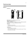
1
ABB Drives
User’s Manual
DeviceNet Adapter Module
RDNA-01
DeviceNet Adapter Module
RDNA-01
User’s Manual
3AFE64504223 REV C
EN
EFFECTIVE: 16.11.2006
© 2006 ABB Oy. All Rights Reserved.
5
Safety instructions
Overview
This chapter states the general safety instructions that must be
followed when installing and operating the RDNA-01 DeviceNet
Adapter module.
The material in this chapter must be studied before attempting any
work on the unit.
In addition to the safety instructions given below, read the
complete safety instructions of the specific drive you are working
on.
General safety instructions
WARNING! All electrical installation and maintenance work on the
drive should be carried out by qualified electricians.
The drive and adjoining equipment must be properly earthed.
Do not attempt any work on a powered drive. After switching off
the mains, always allow the intermediate circuit capacitors 5
minutes to discharge before working on the frequency converter,
the motor or the motor cable. It is good practice to check (with a
voltage indicating instrument) that the drive is in fact discharged
before beginning work.
The motor cable terminals of the drive are at a dangerously high
voltage when mains power is applied, regardless of motor
operation.
There can be dangerous voltages inside the drive from external
control circuits even when the drive mains power is shut off.
Exercise appropriate care when working on the unit. Neglecting
these instructions can cause physical injury or death.
Safety instructions
6
Safety instructions
7
Table of contents
Safety instructions . . . . . . . . . . . . . . . . . . . . . . . . . . . . . . . . . . . . . . . . . . . . 5
Overview . . . . . . . . . . . . . . . . . . . . . . . . . . . . . . . . . . . . . . . . . . . . . . . . . . . . 5
General safety instructions . . . . . . . . . . . . . . . . . . . . . . . . . . . . . . . . . . . . . . . 5
Table of contents . . . . . . . . . . . . . . . . . . . . . . . . . . . . . . . . . . . . . . . . . . . . . 7
Introduction . . . . . . . . . . . . . . . . . . . . . . . . . . . . . . . . . . . . . . . . . . . . . . . . 11
Intended audience . . . . . . . . . . . . . . . . . . . . . . . . . . . . . . . . . . . . . . . . . . . .
Before you start . . . . . . . . . . . . . . . . . . . . . . . . . . . . . . . . . . . . . . . . . . . . . .
What this manual contains . . . . . . . . . . . . . . . . . . . . . . . . . . . . . . . . . . . . . .
Further Information . . . . . . . . . . . . . . . . . . . . . . . . . . . . . . . . . . . . . . . . . . . .
11
11
11
12
Overview . . . . . . . . . . . . . . . . . . . . . . . . . . . . . . . . . . . . . . . . . . . . . . . . . . . 13
Overview . . . . . . . . . . . . . . . . . . . . . . . . . . . . . . . . . . . . . . . . . . . . . . . . . . .
DeviceNet Bus topology . . . . . . . . . . . . . . . . . . . . . . . . . . . . . . . . . . . . . . . .
The RDNA-01 DeviceNet Adapter module . . . . . . . . . . . . . . . . . . . . . . . . . .
Compatibility . . . . . . . . . . . . . . . . . . . . . . . . . . . . . . . . . . . . . . . . . . . . . . .
Delivery check . . . . . . . . . . . . . . . . . . . . . . . . . . . . . . . . . . . . . . . . . . . . .
Warranty and liability information . . . . . . . . . . . . . . . . . . . . . . . . . . . . . . .
13
13
14
15
15
16
Quick start-up guide . . . . . . . . . . . . . . . . . . . . . . . . . . . . . . . . . . . . . . . . . 17
Overview . . . . . . . . . . . . . . . . . . . . . . . . . . . . . . . . . . . . . . . . . . . . . . . . . . .
PLC Configuration . . . . . . . . . . . . . . . . . . . . . . . . . . . . . . . . . . . . . . . . . . . .
Mechanical and electrical installation . . . . . . . . . . . . . . . . . . . . . . . . . . . . . .
Drive configuration . . . . . . . . . . . . . . . . . . . . . . . . . . . . . . . . . . . . . . . . . . . .
Example Configurations . . . . . . . . . . . . . . . . . . . . . . . . . . . . . . . . . . . . . .
17
17
21
21
22
Table of contents
8
Mechanical installation . . . . . . . . . . . . . . . . . . . . . . . . . . . . . . . . . . . . . . . . 25
Mounting . . . . . . . . . . . . . . . . . . . . . . . . . . . . . . . . . . . . . . . . . . . . . . . . . . . . 25
Electrical installation . . . . . . . . . . . . . . . . . . . . . . . . . . . . . . . . . . . . . . . . . 27
Overview . . . . . . . . . . . . . . . . . . . . . . . . . . . . . . . . . . . . . . . . . . . . . . . . . . . .
General cabling instructions . . . . . . . . . . . . . . . . . . . . . . . . . . . . . . . . . . . . .
DIP switch settings . . . . . . . . . . . . . . . . . . . . . . . . . . . . . . . . . . . . . . . . . . . .
DeviceNet connection . . . . . . . . . . . . . . . . . . . . . . . . . . . . . . . . . . . . . . . . . .
27
27
27
29
Drive Configuration . . . . . . . . . . . . . . . . . . . . . . . . . . . . . . . . . . . . . . . . . . 31
Overview . . . . . . . . . . . . . . . . . . . . . . . . . . . . . . . . . . . . . . . . . . . . . . . . . . . . 31
DeviceNet connection configuration . . . . . . . . . . . . . . . . . . . . . . . . . . . . . . . 31
Control locations . . . . . . . . . . . . . . . . . . . . . . . . . . . . . . . . . . . . . . . . . . . . . . 31
Master configuration . . . . . . . . . . . . . . . . . . . . . . . . . . . . . . . . . . . . . . . . . 41
Overview . . . . . . . . . . . . . . . . . . . . . . . . . . . . . . . . . . . . . . . . . . . . . . . . . . . . 41
Configuring the system . . . . . . . . . . . . . . . . . . . . . . . . . . . . . . . . . . . . . . . . . 41
EDS files . . . . . . . . . . . . . . . . . . . . . . . . . . . . . . . . . . . . . . . . . . . . . . . . . . . . 41
Communication profiles . . . . . . . . . . . . . . . . . . . . . . . . . . . . . . . . . . . . . . . 43
The ODVA AC/DC drive profile . . . . . . . . . . . . . . . . . . . . . . . . . . . . . . . . . . .
ODVA output attributes . . . . . . . . . . . . . . . . . . . . . . . . . . . . . . . . . . . . . . .
ODVA input attributes . . . . . . . . . . . . . . . . . . . . . . . . . . . . . . . . . . . . . . . .
ABB Drives communication profile . . . . . . . . . . . . . . . . . . . . . . . . . . . . . . . .
The control word and the status word . . . . . . . . . . . . . . . . . . . . . . . . . . . .
43
44
45
47
47
Communication . . . . . . . . . . . . . . . . . . . . . . . . . . . . . . . . . . . . . . . . . . . . . . 49
Overview . . . . . . . . . . . . . . . . . . . . . . . . . . . . . . . . . . . . . . . . . . . . . . . . . . . .
Introduction to DeviceNet . . . . . . . . . . . . . . . . . . . . . . . . . . . . . . . . . . . . . . .
Object modelling and functional profiles . . . . . . . . . . . . . . . . . . . . . . . . . . . .
Assembly object . . . . . . . . . . . . . . . . . . . . . . . . . . . . . . . . . . . . . . . . . . . . . .
Drive parameter handling . . . . . . . . . . . . . . . . . . . . . . . . . . . . . . . . . . . . . . .
Class objects . . . . . . . . . . . . . . . . . . . . . . . . . . . . . . . . . . . . . . . . . . . . . . . . .
Table of contents
49
49
49
49
54
54
9
Identity Object, Class 0x01 . . . . . . . . . . . . . . . . . . . . . . . . . . . . . . . . . . . .
DeviceNet Object, Class 0x03 . . . . . . . . . . . . . . . . . . . . . . . . . . . . . . . . .
DeviceNet Connection Object, Class 0x05 . . . . . . . . . . . . . . . . . . . . . . . .
Acknowledge Handler Object, Class 0x2B . . . . . . . . . . . . . . . . . . . . . . . .
Motor Data Object, Class 0x28 . . . . . . . . . . . . . . . . . . . . . . . . . . . . . . . . .
Control Supervisor Object, Class 0x29 . . . . . . . . . . . . . . . . . . . . . . . . . . .
AC/DC-Drive Object, Class 0x2A . . . . . . . . . . . . . . . . . . . . . . . . . . . . . . .
54
57
60
64
65
67
68
Diagnostics . . . . . . . . . . . . . . . . . . . . . . . . . . . . . . . . . . . . . . . . . . . . . . . . . 71
RDNA-01 status codes . . . . . . . . . . . . . . . . . . . . . . . . . . . . . . . . . . . . . . . . .
LED indications . . . . . . . . . . . . . . . . . . . . . . . . . . . . . . . . . . . . . . . . . . . . . .
Installation problems . . . . . . . . . . . . . . . . . . . . . . . . . . . . . . . . . . . . . . . . . .
Drive setup . . . . . . . . . . . . . . . . . . . . . . . . . . . . . . . . . . . . . . . . . . . . . . . . . .
PLC programming . . . . . . . . . . . . . . . . . . . . . . . . . . . . . . . . . . . . . . . . . . . .
Scanner fault indications . . . . . . . . . . . . . . . . . . . . . . . . . . . . . . . . . . . . . . .
71
72
73
73
73
73
Definitions and abbreviations . . . . . . . . . . . . . . . . . . . . . . . . . . . . . . . . . . 75
Technical data . . . . . . . . . . . . . . . . . . . . . . . . . . . . . . . . . . . . . . . . . . . . . . 79
RDNA-01 . . . . . . . . . . . . . . . . . . . . . . . . . . . . . . . . . . . . . . . . . . . . . . . . . . . 79
Fieldbus link . . . . . . . . . . . . . . . . . . . . . . . . . . . . . . . . . . . . . . . . . . . . . . . . . 80
Table of contents
10
Table of contents
11
Introduction
Intended audience
The manual is intended for people responsible for installing,
commissioning and using an RDNA-01 DeviceNet Adapter
module. The reader is expected to have a basic knowledge of
electrical fundamentals, electrical wiring practices and how to
operate the drive and the DeviceNet protocol.
Before you start
It is assumed that the drive is installed and ready to operate before
starting the installation of the extension module.
In addition to conventional installation tools, have the drive
manuals available during the installation as they contain important
information not included in this manual. The drive manuals are
referred to at various points of this document.
What this manual contains
This manual contains information on the wiring, configuration and
use of the RDNA-01 DeviceNet Adapter module.
Safety instructions are featured in the first few pages of this
manual.
Overview contains short descriptions of the DeviceNet protocol
and the RDNA-01 DeviceNet Adapter module, a delivery checklist
and information on the manufacturer’s warranty.
Quick start-up guide contains a short description of how to set
up the RDNA-01 DeviceNet Adapter module using the ACS800
drive as an example.
Mechanical installation contains placing and mounting
instructions for the module.
Electrical installation contains wiring, bus termination and
earthing instructions.
Introduction
12
Drive configuration explains how to program the drive before the
communication through the adapter module can be started.
Master configuration explains how to program the DeviceNet
master before communication through the adapter module can be
started.
Communication profiles describes the communication profiles
used in the communication between the DeviceNet network, the
RDNA-01 module and the drive.
Communication contains a description of the DeviceNet
functionality supported by the RDNA-01.
Diagnostics explains how to trace faults with the status LEDs on
the RDNA-01 module.
Definitions and abbreviations explains definitions and
abbreviations concerning the DeviceNet protocol family.
Technical data contains information on physical dimensions,
configurable settings and connectors of the module and a
specification of the DeviceNet link.
Further Information
Further information on the DeviceNet protocol is available on the
world wide web from www.odva.org.
Introduction
13
Overview
Overview
This chapter contains a short description of DeviceNet bus
topology, the RDNA-01 Adapter module, a delivery checklist, and
warranty information.
Further information can be obtained from www.odva.org.
DeviceNet Bus topology
The DeviceNet network has a linear bus topology. Terminating
resistors are required on each end of the trunk line. Drop lines as
long as 6 metres (20 feet) each are permitted, allowing one or
more nodes to be attached. DeviceNet allows branching
structures only on drop lines. An example of an allowable topology
is shown in Figure 1.
Trunk line
Tap
Node
Node
Node
Tap
Node
Node
Node
Terminating
Resistor
Tap
Node
Node
Tap
Node
Drop line
Node
Node
Figure 1. DeviceNet bus topology
Overview
14
The maximum length of trunk cable depends on the data rate and
on the type of the cable used (see chapter Technical data).
Terminating resistor
The DeviceNet network should be terminated at both ends of the
trunk cable with a 121 ohm, ¼ W, 1% Metal Film resistor. Connect
this resistor between the two signal wires (CAN_H, CAN_L) on the
DeviceNet cable.
The RDNA-01 DeviceNet Adapter module
The RDNA-01 DeviceNet Adapter module is an optional device for
ABB drives which enables the connection of the drive to a
DeviceNet system. The drive is considered as a slave in the
DeviceNet network. Through the RDNA-01 DeviceNet Adapter
module it is possible to:
• give control commands to the drive
(Start, Stop, Run enable, etc.)
• feed a motor speed or torque reference to the drive
• give a process actual value or a process reference to the PID
controller of the drive
• read status information and actual values from the drive
• read and write drive parameter values
• reset a drive fault.
The RDNA-01 acts as a Class 2 slave only with predefined
master-slave connection set services. These include the Explicit
Messaging, the Poll-Response service and the Change of State/
Cyclic service. The DeviceNet commands and services supported
by the RDNA-01 DeviceNet Adapter module are discussed in
chapter Communication. Please refer to the user documentation
of the drive as to which commands are supported by the drive.
Overview
15
The adapter module is mounted into its option slot inside the drive.
See the Hardware Manual of the drive.
DeviceNet
master
Terminal block for the bus cable
connection (see chapter
Electrical installation)
Slave
stations
Fixing screw
(frame)
(GND)
X1
8 DIP switches for selecting
node address number and bus
speed
ABB Drive
Status LEDs
(See chapter Diagnostics)
ABB Drive
Figure 2. The construction of the DeviceNet link and the module
layout of the RDNA-01
Compatibility
The RDNA-01 is compatible with all scanners working according
to ODVA DeviceNet specifications.
Delivery check
The option package for the RDNA-01 DeviceNet Adapter module
contains:
• RDNA-01 module
• two screws (M3x10)
• this manual.
Overview
16
Warranty and liability information
The manufacturer warrants the equipment supplied against
defects in design, materials and workmanship for a period of
twelve (12) months after installation or twenty-four (24) months
from date of manufacturing, whichever first occurs. The local ABB
office or distributor may grant a warranty period different to the
above and refer to local terms of liability as defined in the supply
contract.
The manufacturer is not responsible for
• any costs resulting from a failure if the installation,
commissioning, repair, alternation, or ambient conditions of the
drive do not fulfil the requirements specified in the
documentation delivered with the unit and other relevant
documentation
• units subjected to misuse, negligence or accident
• units comprised of materials provided or designs stipulated by
the purchaser.
In no event shall the manufacturer, its suppliers or subcontractors
be liable for special, indirect, incidental or consequential damages,
losses or penalties.
If you have any questions concerning your ABB drive, please
contact the local distributor or ABB office. The technical data,
information and specifications are valid at the time of printing. The
manufacturer reserves the right to modifications without prior
notice.
Overview
17
Quick start-up guide
Overview
This chapter presents the steps to take during the start-up of the
RDNA-01 DeviceNet Adapter Module. For more detailed
information, see the chapters Mechanical installation, Electrical
installation, and Drive Configuration elsewhere in this manual.
WARNING! Follow the safety instructions given in this manual and
the Hardware Manual of the drive.
PLC Configuration
This is an example on how to configure an Allen-Bradley
ControlLogix 5555 PLC with a 1756-DNB 1756 DeviceNet
Scanner to use an ACS800 equipped with an RDNA-01 fieldbus
adapter.
• Select and import the EDS file for drive, for example
ACS800_Standard_RDNA01_appl1.36_Typical_filerev3.2.EDS.
For more help on choosing the correct file, refer to ABB EDS
Selection Guide document delivered with the EDS files.
Note: Only one EDS file with the same Product ID and Vendor
code can be installed in the PLC at a time.
Quick start-up guide
18
• Add drive to network in RSNetWorx for DeviceNet.
• Configure device MAC address.
Quick start-up guide
19
• Configure the DeviceNet Scanner. Add the drive to Scanlist and
edit I/O parameters. Select Polled or Change of State/Cyclic.
Then enter the input and output sizes of the I/O assemblies that
will be used (e.g. for Basic Speed Control Assemblies 20 and
70, each size is set to 4 bytes.)
• For convenience, you can also edit the Input and Output
memory mappings. By default the two 16-bit input words are
mapped into a single 32-bit double word. It is more convenient,
however, to map them into separate double words. Output
words can be mapped similarly.
Quick start-up guide
20
• Download the scanner settings to the device in online mode.
• Add your DeviceNet scanner to an RSLogix 5000 project. You
should get new Controller Tags Local:<slot>:I and
Local:<slot>:O. You can use them to access the data as
mapped above:
Local:<slot>:O.Data[0] is the Control Word
Local:<slot>:O.Data[1] is the Reference
Local:<slot>:I.Data[0] is the Status Word
Local:<slot>:I.Data[1] is the Actual Value
Note: You may need to change the value of
Local:<slot>:O.CommandRegister.Run or
Local:<slot>:I.CommandRegister.Run to 1.
Quick start-up guide
21
Mechanical and electrical installation
• Insert the RDNA-01 into its specified slot in the drive.
• Fasten the screws.
• Plug the fieldbus connector into the module.
Drive configuration
Note: Configuring the drive for communication with the module is
dependent on the drive type. Refer to the Firmware Manual of the
drive for detailed information on configuring the drive to use the
communication module.
• Power up the drive.
• Configure drive to enable module. With an ACS550 drive, set
parameter 98.02 COMM PROT SEL to EXT FBA. With an
ACS800 drive, set parameter 98.02 COMM. MODULE LINK to
FIELDBUS.
• Verify that FBA TYPE is DEVICENET. On the ACS800 drive,
this is parameter 51.01.
• With ACS800, set parameter 98.07 COMM PROFILE according
to your assembly instance selection. See the table in section
communication profiles for more information. This is not needed
with ACS550.
• Configure drive to accept Start/Stop, Direction, Reference, Run
Enable and Fault Reset from module. Examples of appropriate
values on the ACS800 are shown in the following tables.
• Configure module via fieldbus configuration groups for desired
network characteristics. Examples of appropriate values on the
ACS800 are shown in the following tables.
• Initiate a “Fieldbus adapter parameter refresh” by setting
parameter 51.27 FBA PAR REFRESH.
Quick start-up guide
22
Note: The new settings take effect only when the module is
powered up the next time or when a ‘Fieldbus Adapter parameter
refresh’ is given (see the drive documentation).
Example Configurations
ODVA Basic Speed Control on ACS800
Drive Parameter
Example setting for ACS800
10.01 EXT1 STRT/STP/DIR
COMM.CW
10.03 REF DIRECTION
REQUEST
11.03 EXT REF1 SELECT
COMM. REF
16.01 RUN ENABLE
YES
16.04 FAULT RESET SEL
COMM.CW
51.01 MODULE TYPE
DEVICENET (Verify only)
51.02 Module MacID
2
51.03 Module baud rate
2 (500 kbit/s)
51.04 HW/SW option
1 (use software settings)
51.05 Stop function
0 (ramp stop)
51.06 Output instance
20 (ODVA Basic Speed Control)
51.07 Input instance
70 (ODVA Basic Speed Control)
98.02 COMM MODULE LINK
FIELDBUS
98.07 COMM PROFILE
GENERIC
Quick start-up guide
23
ABB Profile on ACS800
Drive Parameter
Example setting for ACS800
10.01 EXT1 STRT/STP/DIR
COMM.CW
10.03 REF DIRECTION
REQUEST
11.03 EXT REF1 SELECT
COMM. REF
16.01 RUN ENABLE
YES
16.04 FAULT RESET SEL
COMM.CW
51.01 MODULE TYPE
DEVICENET
51.02 Module MacID
2
51.03 Module baud rate
2 (500 kbit/s)
51.04 HW/SW option
1 (use software settings)
51.05 Stop function
0 (ramp stop)
51.06 Output instance
100 (ABB Drives Control Assembly)
51.07 Input instance
101 (ABB Drives Input Assembly)
98.02 COMM MODULE LINK
FIELDBUS
98.07 COMM PROFILE
ABB DRIVES
Quick start-up guide
24
ABB Profile with user specific assemblies on ACS800
Drive Parameter
Example setting for ACS800
10.01 EXT1 STRT/STP/DIR
COMM.CW
10.03 REF DIRECTION
REQUEST
11.03 EXT REF1 SELECT
COMM. REF
16.01 RUN ENABLE
YES
16.04 FAULT RESET SEL
COMM.CW
51.01 MODULE TYPE
DEVICENET
51.02 Module MacID
2
51.03 Module baud rate
2 (500 kbit/s)
51.04 HW/SW option
1 (use software settings)
51.05 Stop function
0 (ramp stop)
51.06 Output instance
102 (User Specific Assembly)
51.07 Input instance
103 (User Specific Assembly)
51.08 Output I/O par 1
1 (data set 1, 1st word = Control Word)
51.09 Output I/O par 2
2 (data set 1, 2nd word = Reference 1)
51.10 Output I/O par 3
1202 (12.02 CONST SPEED 1)
51.11 Output I/O par 4
1203 (12.03 CONST SPEED 2)
51.12 Input I/O par 1
4 (data set 2, 1st word = Status Word)
51.13 Input I/O par 2
5 (data set 2, 2nd word = Actual 1)
51.14 Input I/O par 3
104 (01.04 CURRENT)
51.15 Input I/O par 4
106 (01.06 POWER)
51.26 VSA I/O size
4 (use 4 words input and output)
98.02 COMM MODULE LINK
FIELDBUS
98.07 COMM PROFILE
ABB DRIVES
Note: Remember to change the size of transferred data in the
DeviceNet scanner settings.
Quick start-up guide
25
Mechanical installation
WARNING! Follow the safety instructions given in this manual and
in the Hardware Manual.
Mounting
The RDNA-01 is to be inserted into its option slot inside the drive.
The module is held in place with plastic retaining clips and two
screws. The screws also provide the earthing of the I/O cable
shield connected to the module, and interconnect the GND signals
of the module and the control board of the drive.
On installation of the module, the signal and power connection to
the drive is automatically made through a 34-pin connector.
Mounting procedure:
• Insert the module carefully into its position inside the drive until
the retaining clips lock the module into position.
• Fasten the two screws (included) to the stand-offs.
Note: Correct installation of the screws is essential for fulfilling the
EMC requirements and for proper operation of the module.
Mechanical installation
26
Mechanical installation
27
Electrical installation
Overview
This chapter contains:
• general cabling instructions
• instructions for setting the module node address number and
communication speed (bit rate)
• instructions for connecting the module to the DeviceNet bus.
WARNING! Before installation, switch off the drive power supply.
Wait 5 minutes to ensure that the capacitor bank of the drive is
discharged. Switch off all dangerous voltages connected from
external control circuits to the inputs and outputs of the drive.
General cabling instructions
Arrange the bus cables as far away from the motor cables as
possible. Avoid parallel runs. Use bushings at cable entries.
DIP switch settings
DIP switches on the printed circuit board of the RDNA-01 are used
to select node address number and bus speed for the module.
Use the table below to set the values. Note that switch 3 is the
most significant bit of the node address number.
Electrical installation
28
Bit rate
Binary
125 kbit/s
00
DIP switch
DIP
ON 1 2 3 4 5 6 7 8
250 kbit/s
01
DIP
ON 1 2 3 4 5 6 7 8
500 kbit/s
10
DIP
ON 1 2 3 4 5 6 7 8
Node no.
Binary
1
000001
DIP
ON 1 2 3 4 5 6 7 8
2
000010
DIP
ON 1 2 3 4 5 6 7 8
•••
•••
63
111111
•••
DIP
ON 1 2 3 4 5 6 7 8
Electrical installation
29
DeviceNet connection
The bus cable is connected to terminal block X1 on the RDNA-01.
The terminal block is described below.
X1
Description
1
V-
Isolated ground
2
CAN_L
CAN_L bus line
3
SHLD
Network cable shield
4
CAN_H CAN_H bus line
5
V+
Isolated 24V DC voltage supply
DeviceNet bus termination
The DeviceNet bus line must be terminated with 121 ohm
resistors connected between the CAN_L and CAN_H wires at
each end as shown below.
Scanner
Node 1
• • •
Node n
CAN_H
121 ohm
1%
Metal Film
1/4 W
CAN_L
121 ohm
1%
Metal Film
1/4 W
Electrical installation
30
Connection examples
5-pin micro-style connector
0V
Network
power supply +24 V
VCAN_L
SHLD
CAN_H
V+
1 2 3 4 5
VCAN_L
SHLD
CAN_H
V+
1 2 3 4 5
Male micro-style
2
connector
1
3
4
5
4
5
3
2
1
RDNA
X1
5-pin mini-style connector
0V
Network
power supply +24 V
Male mini-style
connector
2
1
3
4
2
5
4
5
1
3
RDNA
X1
Standard open-style screw connector
Electrical installation
VCAN_L
SHLD
CAN_H
V+
1 2 3 4 5
1 2 3 4 5
+24 V
Network
power supply 0 V
RDNA
X1
31
Drive Configuration
Overview
This chapter gives information on configuring the RDNA-01
DeviceNet Adapter module.
DeviceNet connection configuration
The detailed procedure of activating the module for
communication with the drive is dependent on the drive type.
(Normally, a parameter must be adjusted to activate the
communication. See the drive documentation.)
As communication between the drive and the RDNA-01 is
established, several configuration parameters are copied to the
drive. These parameters (shown in Table 3.) must be checked first
and adjusted if necessary. The alternative selections for these
parameters are discussed in more detail below the table.
Note: The new settings take effect only when the module is
powered up the next time or when the module receives a ‘Fieldbus
Adapter parameter refresh’ command from the drive.
Control locations
ABB drives can receive control information from multiple sources
including digital inputs, analogue inputs, the drive control panel
and a communication module (e.g. RDNA-01). ABB drives allow
the user to separately determine the source for each type of
control information (Start, Stop, Direction, Reference, Fault Reset,
etc.). In order to give the fieldbus Scanner the most complete
control over the drive, the communication module must be
selected as source for this information. See the user
documentation of the drive for information on the selection
parameters.
Drive Configuration
32
Table 3. The RDNA-01 configuration parameters
Fieldbus Parameter name
par. no.
Alternative settings
Default
setting
1
MODULE TYPE
DEVICENET
DEVICENET
2
Module MacID
0 … 63
63
3
Module Baud rate
0 = 125 kBit/s; 1 = 250 kBit/s;
2 = 500 kBit/s
0
4
HW/SW Option
0 = Hardware 1 = Software
0
5
Stop Function
0 = Ramp stop; 1 = Coast stop
0
6
Output Instance
20 … 102
20
7
Input Instance
70 … 103
70
8
Output I/O Par 1
0 … 32767
0
9
Output I/O Par 2
0 … 32767
0
10
Output I/O Par 3
0 … 32767
0
11
Output I/O Par 4
0 … 32767
0
12
Input I/O Par 1
0 … 32767
0
13
Input I/O Par 2
0 … 32767
0
14
Input I/O Par 3
0 … 32767
0
15
Input I/O Par 4
0 … 32767
0
16
Output I/O Par 5
0 … 32767
0
17
Output I/O Par 6
0 … 32767
0
18
Output I/O Par 7
0 … 32767
0
19
Output I/O Par 8
0 … 32767
0
20
Output I/O Par 9
0 … 32767
0
21
Input I/O Par 5
0 … 32767
0
22
Input I/O Par 6
0 … 32767
0
23
Input I/O Par 7
0 … 32767
0
24
Input I/O Par 8
0 … 32767
0
Drive Configuration
33
25
Input I/O Par 9
0 … 32767
0
26
VSA I/O Size
1…9
4
Note: The Default values are used when the module is connected
to the drive for the first time. The parameters in the fieldbus group
must be set up for the current application.
01 MODULE TYPE
Shows the connected communication option module type.
02 Module MacID
Selects the MAC ID for the node.
0 … 63
On a DeviceNet network, each node is identified by a unique node
number. This node number is between 0 and 63, and it is called
MAC ID.
Note: When parameter 04 HW/SW Option is set to 0=HW this
parameter is read-only and its value is set by DIP switches. See
chapter Electrical installation.
03 Module Baud rate
Sets the baud rate for the DeviceNet interface. This is user
selectable, but must be the same on every node on the DeviceNet
network.
0 = 125 kBit/s; 1 = 250 kBit/s; 2 = 500 kBit/s
Note: When parameter 04 HW/SW Option is set to 0=HW this
parameter is read-only and its value is set by DIP switches. See
chapter Electrical installation.
Drive Configuration
34
04 HW/SW Option
Defines the selection source of module MacID and baud rate.
0 = selection of MAC ID and baud rate via the DIP switches
enabled.
1 = selection of MAC ID and baud rate via parameters 02 and 03
and via the DeviceNet Object enabled (see chapter
Communication sub-section DeviceNet Object, Class 0x03).
05 Stop Function
Defines the method for stopping the motor with instances 20 and
21.
0 = Ramp stop: the motor decelerates along the active
deceleration ramp.
1 = Coast stop: the motor comes to a stop by coasting.
Drive Configuration
35
06 Output Instance
07 Input Instance
These parameters define the preferred output and input
assemblies respectively.
The instances 20, 70, 21 and 70 are so-called Drive Profile
instances as defined in the ODVA DeviceNet specification (AC/DC
Drive profile). The instances 100, 101, 102 and 103 are so-called
ABB Drives instances as defined by ABB, i.e. the control word,
status word, speed reference and speed actual value are defined
by the ABB Drives communication profile.
The static/dynamic property indicates whether the data length of
the instance is fixed or adjustable.
Output instances (from master to drive)
Instance Assembly
Static/Dynamic
20
Basic speed control output
Static
21
Extended speed control output Static
100
ABB Drives assembly
Static
102
User specific assembly
Dynamic
Input instances (from drive to master)
Instance Assembly
70
Basic speed control input
71
Extended speed control input
101
ABB Drives assembly
103
User specific assembly
Static/Dynamic
Static
Static
Static
Dynamic
Note: The output instances carry data from the master to the drive
and the input instances from the drive to the master.
Drive Configuration
36
The following table shows the possible combinations of output and
input instances.
Possible instance combinations
Output instance
Input instance
20
21
100
102
70
71
103
70
71
103
101
103
101
103
Communication
profile to be used
Generic Drive profile
Generic Drive profile
Generic Drive profile*
Generic Drive profile
Generic Drive profile
Generic Drive profile*
ABB Drives profile
ABB Drives profile
ABB Drives profile
ABB Drives profile
*(Note: status word (4) and actual value 1 (5) according to the Generic
profile if used)
Selecting an invalid combination will reset the module and
automatically configure the instances as follows:
1) If the output instance is invalid, instance 20 will be selected.
2) If the output instance is valid, but the input instance is invalid,
the default input instance will be selected as follows:
Output instance
20
21
100
102
Drive Configuration
Default input instance
70
71
101
103
37
08 Output I/O Par 1
Defines the data word or drive parameter that can be written with
Assembly object instance 102 (see chapter Communication subsection User Specific assembly).
The content is defined by a decimal number in the range of 0 to
32767 as follows:
0
not used
1 - 99
data set area of the drive
101 - 9999
parameter area of the drive
10000 - 32767
not supported by the drive
The data set area is allocated as follows:
1
data set 1 word 1
2
data set 1 word 2
3
data set 1 word 3
4
data set 2 word 1
5
data set 2 word 2
6
data set 2 word 3
7
data set 3 word 1
…
99
data set 33 word 3
The parameter area is allocated as follows:
Parameter number with format xxyy, where xx is the parameter
group number (0 to 99) and yy is the parameter number index
inside the group (01 to 99).
Note: group 0 is virtual group for the data sets
Drive Configuration
38
09 to 11 Output I/O Par 2 to Output I/O Par 4
See parameter 08 Output I/O Par 1.
12 Input I/O Par 1
Defines a data word or drive parameter that can be read with
Assembly object instance 103 (see chapter Communication subsection User Specific assembly).
The content is defined by a decimal number in the range of 0 to
32767 as follows:
0
not used
1 - 99
data set area of the drive
101 - 9999
parameter area of the drive
10000 - 32767
not supported by the drive
The data set area is allocated as follows:
1
data set 1 word 1
2
data set 1 word 2
3
data set 1 word 3
4
data set 2 word 1
5
data set 2 word 2
6
data set 2 word 3
7
data set 3 word 1
…
99
data set 33 word 3
The parameter area is allocated as follows:
Parameter number with format xxyy, where xx is the parameter
group number (1 to 99) and yy is the parameter number index
inside the group (01 to 99).
13 to 15 Input I/O Par 2 to Input I/O Par 4
See parameter 12 Input I/O Par 1.
Drive Configuration
39
16 to 20 Output I/O Par 5 to Output I/O Par 9
See parameter 08 Output I/O Par 1.
21 to 25 Input I/O Par 5 to Input I/O Par 9
See parameter 12 Input I/O Par 1.
26 VSA I/O Size
Defines the length of the User Specific assembly in words.
1…9
Drive Configuration
40
Drive Configuration
41
Master configuration
Overview
This chapter gives information on configuring the DeviceNet
master station for communication through the RDNA-01
DeviceNet Adapter module.
Configuring the system
After the RDNA-01 DeviceNet Adapter module has been
mechanically and electrically installed according to the instructions
in previous chapters, and has been initialized by the drive, the
master station must be prepared for communication with the
module.
Please refer to the Scanner documentation for information on
configuring the system for communication with the RDNA-01.
EDS files
Electronic Data Sheet (EDS) files specify the properties of the
device for the DeviceNet scanner. The device is identified by the
DeviceNet scanner by means of the Vendor Code, Product Code,
Device Type, and Major Revision of the module software (See
Identity Object 01h).
Note: Only one EDS file with the same DeviceNet Product Code
can be installed in the PLC at a time.
To enable the use of different ABB drive types on the same
DeviceNet network, a unique Product Code has been given to
each drive type and application combination.
The EDS files are available in typical and extended formats. The
typical EDS files include the I/O Assembly configuration properties
and the definition of the parameters in the fieldbus parameter
group (see chapter Drive Configuration) only. The typical EDS files
Master configuration
42
can be used with the corresponding drive and/or application
program independent of the application program revision.
The extended EDS files are intended for applications where
access to the drive parameters via the DeviceNet network is
required. The extended EDS files for ABB drives are specific to
each drive type and application program revision. In addition, most
extended EDS files need to be modified by hand to suit the
application.
Master configuration
43
Communication profiles
Overview
This chapter describes the communication profiles used in the
communication between the DeviceNet network, the RDNA-01
module, and the drive.
Communication profiles
Communication profiles are ways of conveying control commands
(Control word, Status word, references and actual values)
between the master station and the drive.
With the RDNA-01 module, the DeviceNet network may employ
either the ODVA AC/DC drive profile or the ABB Drives profile.
The ODVA AC/DC drive profile
This section briefly describes the ODVA AC/DC Drive profiles.
Additional information can be obtained from www.odva.org.
An DeviceNet node is modelled as a collection of abstract objects.
Each object represents the interface to and behaviour of a
component within the product. The ODVA AC/DC Drive Profiles
define a collection of objects suitable for the control of AC and DC
drives. Objects supported by the RDNA-01 DeviceNet Adapter are
listed in section Class objects on page 54. Objects are defined by:
• Service
• Class
• Instance
• Attribute
• Behaviour
For example, to set the drive speed reference, the
Set_Attribute_Single service can be requested for Attribute
SpeedRef of the Class AC/DC Drive Object. The resulting
Communication profiles
44
behaviour is that the reference speed of the drive is set to the
requested value.
This is an example of Explicit Messaging where each attribute of a
class is set individually. While this is allowed, it is inefficient.
Instead Implicit Messaging using Input and Output Assembly
Instances is recommended. Implicit Messaging allows the
DeviceNet Master to set or get predefined groups of attributes in a
single message exchange. Assembly Instances supported by the
RDNA-01 are listed and defined in chapter Communication, page
49.
ODVA output attributes
This section briefly describes the instances found in the ODVA
AC/DC Drive Profiles output assemblies. Not all attributes listed
here will be supported by all output assembly instances.
Run Forward & Run Reverse (Control Supervisor Object)
These attributes are used to assert run and stop commands to
Control Supervisor Object state machine according to the
following table.
Table 4. Run/Stop event matrix
RunFwd
RunRev
Trigger event
Run type
0
0
Stop
N/A
0!1
0
Run
RunFwd
0
0!1
Run
RunRev
0!1
0!1
No action
N/A
1
1
No action
N/A
0!1
1
Run
RunRev
1
0!1
Run
RunFwd
Fault Reset (Control Supervisor Object)
This attribute resets a drive fault on a transition from zero to one if
the condition that caused the fault has been cleared.
Communication profiles
45
Net Ctrl (Control Supervisor Object)
This attribute requests that the drive Run/Stop command be
supplied locally (Net Ctrl = 0) or by the network (Net Ctrl = 1).
Net Ref (AC/DC Drive Object)
This attribute requests that the drive speed and torque references
be supplied locally (Net Ref = 0) or by the network (Net Ref = 1).
Speed Reference (AC/DC Drive Object)
This attribute is the speed reference for the drive. The units are
scaled by the Speed Scale attribute of the AC/DC Drive Object.
Torque Reference (AC/DC Drive Object)
This attribute is the torque reference for the drive. The units are
scaled by the Torque Scale attribute of the AC/DC Drive Object.
ODVA input attributes
This section briefly describes the instances found in the ODVA
AC/DC Drive Profiles input assemblies. Not all attributes listed
here will be supported by all input assembly instances.
Faulted (Control Supervisor Object)
This attribute indicates that the drive has experienced a fault. The
fault code may be read from the FaultCode attribute of the Control
Supervisor Object.
Warning (Control Supervisor Object)
This attribute indicates that the drive is experiencing a warning
condition. The warning code may be read from the WarnCode
attribute of the Control Supervisor Object.
Running Forward (Control Supervisor Object)
This attribute indicates that the drive is running in the forward
direction.
Running Reverse (Control Supervisor Object)
This attribute indicates that the drive is running in the reverse
direction.
Communication profiles
46
Ready (Control Supervisor Object)
This attribute indicates that the Control Supervisor Object state
machine (see “State” below) is in the Ready, Running or Stopping
state.
Ctrl From Net (Control Supervisor Object)
This attribute indicates if the Run/Stop command is being supplied
locally (Ctrl From Net = 0) or by the network (Ctrl From Net = 1).
Ref From Net (AC/DC Drive Object)
This attribute indicates if the Speed and Torque references are
being supplied locally (Ref From Net = 0) or by the network (Ref
From Net = 1).
At Reference (AC/DC Drive Object)
This attribute indicates the drive is operating at the specified
speed or torque reference.
State (Control Supervisor Object)
This attribute indicates the current state of the Control Supervisor
Object.
Table 5. Control supervisor states
State
Description
State
Description
0
Vendor Specific
4
Enabled
1
Startup
5
Stopping
2
Not Ready
6
Fault Stop
3
Ready
7
Faulted
Communication profiles
47
Power off
Non existent
state
Power on
condition
ALM=1
Faulted
Start-up
ALM
DEC
FWD
RDY
REV
=
=
=
=
=
Alarm
Deceleration
Forward
Ready
Rewind
Power on
FaultRst
DEC=0
Not ready
Power on AND
not RDY
Power on AND
RDY
Ready
Fault stop
DEC=0
Stopping
FWD OR REV
Enabled
ALM=1
DEC=1
ALM=1
ALM=1
Figure 6. State transition diagram
Speed Actual (AC/DC Drive Object)
This attribute indicates the actual speed at which the drive is
operating. The units are scaled by the SpeedScale attribute of the
AC/DC Drive Object.
Torque Actual (AC/DC Drive Object)
This attribute indicates the actual torque at which the drive is
operating. The units are scaled by the Torque Scale attribute of
the AC/DC Drive Object.
ABB Drives communication profile
The control word and the status word
The Control Word is the principal means for controlling the drive
from a fieldbus system. It is sent by the fieldbus master station to
the drive through the adapter module. The drive switches between
its states according to the bit-coded instructions on the Control
Word, and returns status information to the master in the Status
Word.
Communication profiles
48
Communication profiles
49
Communication
Overview
This chapter describes the DeviceNet communication protocol for
the RDNA-01 and the configuration of the scanner. For detailed
information on DeviceNet communication, refer to ODVA
DeviceNet Specifications Release 2.0.
Introduction to DeviceNet
DeviceNet is a protocol based on CAN technology. CAN specifies
the physical layer interface. DeviceNet specifies the wiring, and
the data transfer through CAN.
The RDNA-01 is a device acting as a Group 2 only Server
realising the Predefined Master Slave Connection Set
functionality. The Off-line Connection Set functionality and UCMM
are not supported.
Object modelling and functional profiles
One of the main features of DeviceNet is object modelling. A
group of objects can be described with a Functional Profile. The
RDNA-01 realises the ODVA AC/DC Drive Functional Profile with
additional features.
Assembly object
I/O Assembly Instances may also be referred to as Block Transfer
of data. Intelligent devices realising a Functional Profile, such as
the RDNA-01, have several objects. Since it is not possible to
transmit more than one object data through a single connection, it
is practical and more efficient to group attributes from different
objects into a single I/O connection (for example a Polled
Connection) using the Assembly object. The Assembly object acts
as a tool for grouping these attributes.
Communication
50
The Assembly selections described above are in fact Instances of
the Assembly object class. The RDNA-01 uses Static assemblies
(in other words, fixed groupings of different object data only),
except for the User Specific Assembly. These are predefined and
cannot be changed.
The following tables describe the predefined assembly instances
supported by the RDNA-01.
BASIC SPEED CONTROL assembly
The BASIC SPEED CONTROL assembly is defined by ODVA
AC/DC Drive Profile. The format of the output assembly is:
Instance 20
Byte Bit 7 Bit 6 Bit 5 Bit 4 Bit 3 Bit 2
Bit 1 Bit 0
0
Fault reset
Run fwd
1
2
Speed Reference (Low Byte)
3
Speed Reference (High Byte)
The format of the input assembly is:
Instance 70
Byte Bit 7 Bit 6 Bit 5 Bit 4 Bit 3
Bit 2
Bit 1 Bit 0
0
Running 1
Faulted
1
2 Speed Actual Value (Low Byte)
3 Speed Actual Value (High Byte)
The unit of speed reference and actual is rpm.
Note: If the BASIC SPEED CONTROL or the EXTENDED SPEED
CONTROL assembly is used, it must be ensured that the fieldbus
is selected as the drive control source and fieldbus specific
(Generic Drive profile) Control/Status Word format is selected
instead of ABB Drives profile.
Communication
51
EXTENDED SPEED CONTROL assembly
The EXTENDED SPEED CONTROL assembly is defined by
ODVA AC/DC Drive Profile. The format of the output assembly is:
Instance 21
Byte Bit 7 Bit 6 Bit 5 Bit 4 Bit 3 Bit 2
0
NetRef NetCtrl
Fault
Reset
1
2 Speed Reference (Low Byte)
3 Speed Reference (High Byte)
Bit 1
Bit 0
Run
Run
Reverse Forward
The format of the input assembly is:
Instance 71
Byte Bit 7 Bit 6 Bit 5 Bit 4 Bit 3
Bit 2
Bit 1 Bit 0
0 At
Ref Ctrl Ready Running Running Warn- Faulted
Refer- From From
Reverse Forward ing
ence Net Net
1 Drive State (see section State (Control Supervisor Object)
on page 46)
2 Speed Actual (Low Byte)
3 Speed Actual (High Byte)
Note: With ACx550 the Ctrl From Net bit reflects the status of
NetCtrl. With ACS800 it indicates if any of the control word bits
can be used to control the drive. For example, if 16.04 FAULT
RESET SEL is COMM, the bit is always fixed to 1.
ABB Drives assembly
ABB Drives assembly allows the use of the ABB Drives
communication profile. The format of the output assembly is:
Instance 100
Byte Bit 7 Bit 6 Bit 5 Bit 4 Bit 3
0 Control Word (Low Byte)
1 Control Word (High Byte)
2 Set Speed (Low Byte), unscaled
3 Set Speed (High Byte), unscaled
Bit 2
Bit 1
Bit 0
Communication
52
The format of the input assembly is:
Instance 101
Byte Bit 7 Bit 6 Bit 5 Bit 4 Bit 3 Bit 2
0 Status Word (Low Byte)
1 Status Word (High Byte)
2 Actual Speed (Low Byte), unscaled
3 Actual Speed (High Byte), unscaled
Bit 1
Bit 0
User Specific assembly
User Specific assembly allows the use of the ABB Drives
communication profile. The format of the output assembly is:
Instance 102
Byte Bit 7 Bit 6 Bit 5 Bit 4
0 Output I/O 1 (Low Byte)
1 Output I/O 1 (High Byte)
2 Output I/O 2 (Low Byte)
3 Output I/O 2 (High Byte)
4 Output I/O 3 (Low Byte)
5 Output I/O 3 (High Byte)
6 Output I/O 4 (Low Byte)
7 Output I/O 4 (High Byte)
8 Output I/O 5 (Low Byte)
9 Output I/O 5 (High Byte)
10 Output I/O 6 (Low Byte)
11 Output I/O 6 (High Byte)
12 Output I/O 7 (Low Byte)
13 Output I/O 7 (High Byte)
14 Output I/O 8 (Low Byte)
15 Output I/O 8 (High Byte)
16 Output I/O 9 (Low Byte)
17 Output I/O 9 (High Byte)
Bit 3
Bit 2
Bit 1
Bit 0
The value of Output I/O 1 to 9 sets the data word or drive
parameter defined by Output I/O Par 1 to 9 respectively. See
chapter Drive Configuration.
Communication
53
The format of the input assembly is:
Instance 103
Byte Bit 7 Bit 6 Bit 5 Bit 4
0 Input I/O 1 (Low Byte)
1 Input I/O 1 (High Byte)
2 Input I/O 2 (Low Byte)
3 Input I/O 2 (High Byte)
4 Input I/O 3 (Low Byte)
5 Input I/O 3 (High Byte)
6 Input I/O 4 (Low Byte)
7 Input I/O 4 (High Byte)
8 Input I/O 5 (Low Byte)
9 Input I/O 5 (High Byte)
10 Input I/O 6 (Low Byte)
11 Input I/O 6 (High Byte)
12 Input I/O 7 (Low Byte)
13 Input I/O 7 (High Byte)
14 Input I/O 8 (Low Byte)
15 Input I/O 8 (High Byte)
16 Input I/O 9 (Low Byte)
17 Input I/O 9 (High Byte)
Bit 3
Bit 2
Bit 1
Bit 0
The value of Input I/O 1 to 9 is read from the data word or drive
parameter defined by Input I/O Par 1 to 9 respectively. See
chapter Drive Configuration.
Note: If the BASIC SPEED CONTROL or the EXTENDED SPEED
CONTROL assembly is used, it must be ensured that the fieldbus
is selected as the drive control source and fieldbus specific
(Generic Drive profile) Control/Status Word format is selected
instead of ABB Drives profile.
Communication
54
Drive parameter handling
With the RDNA-01, drive parameters can also be accessed. The
function is implemented by employing the so-called Explicit
Messaging properties of the DeviceNet protocol. Explicit
Messaging makes use of objects consisting of three parts, Class,
Instance, and Attribute.
Class is always 144 (90h). Instance and Attribute correspond to
the drive parameter Group and Index in the following way:
• Instance = Parameter Group (01…99)
• Attribute = Parameter Index (01…99)
For example, Parameter 99.01 is accessed as follows:
• Class = 144 = 0x90
• Instance = 99 = 0x63
• Attribute = 1 = 0x01.
In addition, the instance 100 (0x64) can be used to access the
data sets using explicit messaging. The first word of data set 2, for
example, can be accessed with class 0x90, instance 0x64
attribute 4. Refer to the drive firmware manual for more
information.
Class objects
Legend:
Data type
UINT8
Unsigned Integer 8 bit
UINT16
Unsigned Integer 16 bit
SINT16
Signed Integer 16 bit
UINT32
Unsigned Integer 32 bit
BOOL
Boolean value
Identity Object, Class 0x01
This object provides identification of and general information
about the device.
Communication
55
Class Attributes
# Attribute
name
Services Description
Default,
Data type
Minimum,
Maximum
Revision of the Identity Object 1,1,1
Array of
UINT8
1 Revision
Get
Instance Attributes
# Attribute
name
Services Description
1 Vendor ID
Get
2 Device
Type
3 Product
Code
4 Revision
Get
Get
5 Status
Get
6 Serial
Number
7 Product
Name
Get
Get
Get
Identification of the device
vendor.
Identification of the general
product type
Assigned vendor code to
describe the device
Revision of the item the
Identity Object represents
Summary Status of the
Device
Serial Number of the
DeviceNet module
Product identification. Max 32
characters.
Default,
Data type
Minimum,
Maximum
46
UINT16
2
UINT16
N/A,N/A,
N/A
UINT16
Array[UINT
8 UINT8]
UINT16
0,0,255
N/A,N/A,
N/A
RDNA-01
and ACS
xxx
UINT32
Short
String
Attribute explanations
Vendor ID
Vendor IDs are managed by the Open DeviceNet Vendor
Association, Inc. (ODVA). The ABB Vendor ID is 46.
Device Type
The list of device types is managed by ODVA. It is used to identify
the device profile that a particular product is using.
E.g. 2 = AC drive, 13 = DC drive
Communication
56
Product Code
Every ABB drive type or application of the drive has a dedicated
product code.
Revision
Revision attribute, which consists of Major and Minor Revisions,
identifies the Revision of the item the Identity Object is
representing.
Status
This attribute represents the current status of the entire device. Its
value changes as the state of the device changes. The Status
attribute is a WORD, with the following bit definitions:
Bit(s)
Type/Name
0
Owned
1
2
3
4,5,6,7
8
9
10
Definition
TRUE indicates the device (or an object within
the device) has an owner. Within the
Master/Slave paradigm the setting of this bit
means that the Predefined Master/Slave
Connection Set has been allocated to a
master. Outside the Master/Slave paradigm
the meaning of this bit is to be defined.
Reserved, set to 0.
Configured
TRUE indicates the application of the device
has been configured to do something that
differs from the “out–of–box” default. This
does not include configuration of the
communications.
Reserved, set to 0.
Vendor–specific
Minor Recoverable
TRUE indicates the device detected a
Fault
recoverable problem. The problem does not
cause the device to go into a faulted state.
Minor
TRUE indicates the device detected a
Unrecoverable Fault unrecoverable problem. The problem does not
cause the device to go into a faulted state.
Major Recoverable
TRUE indicates the device detected a problem
Fault
which caused the device to go into the “Major
Recoverable Fault” state.
Communication
57
Bit(s)
Type/Name
Definition
11
Major
TRUE indicates the device detected a problem
Unrecoverable Fault which caused the device to go into the “Major
Unrecoverable Fault” state.
12,13,14,15
Reserved, set to 0.
Serial Number:
This attribute is a number used in conjunction with the Vendor ID
to form a unique identifier for each device on DeviceNet.
Product Name:
This text string should represent a short description of the
product/product family represented by the product code in
attribute 3.
Configuration Consistency Value:
A product may automatically modify the Configuration
Consistency Value whenever any non-volatile attribute is altered.
DeviceNet Object, Class 0x03
The DeviceNet Object provides the configuration and status of a
DeviceNet port. Each DeviceNet product must support one (and
only one) DeviceNet object per physical connection to the
DeviceNet communication link.
Class Attributes
# Attribute
name
Services
Description
Data type
1 Revision
Get_Attribute_Single
Revision of the DeviceNet
Object Class Definition upon
which the implementation is
based
Array of
UINT8
Communication
58
Instance Attributes
# Attribute
name
Services
1 MAC ID
2 Baud Rate
Get_Attribute_Single
Get_Attribute_Single
5 Allocation
Get_Attribute_Single
information
6 MAC ID
switch
changed
7 Baudrate
changed
Get_Attribute_Single
Get_Attribute_Single
Description
Default,
Data type
Minimum,
Maximum
Node address
-,0,63
UINT8
The baud rate of the -,0,2
UINT8
device
Allocation Choice
N/A,N/A, Struct
Master’s Mac ID
N/A
UINT8
UINT8
1 = MAC ID switching N/A,N/A, UINT8
changed since start- N/A
up
1 = Baudrate
N/A,N/A, UINT8
changed since start- N/A
up
The MAC switch
N/A,N/A, UINT8
position
N/A
8 Actual MAC Get_Attribute_Single
switch
position
9 Actual
Get_Attribute_Single The Baudrate switch N/A,N/A,
Baudrate
position
N/A
switch
position
UINT8
The Allocation Information attribute consists of the following:
Allocation Choice Byte
The Allocation Choice byte indicates which of the Predefined
Master/Slave Connections are active (in the Configuring, or
Established state).
The Allocation Choice byte is initialized to 00 at device power–up
or reset.
Master’s MAC ID
The range of values is 0 to 63 and 255 decimal. A value in the
range of 0 … 63 indicates that the Predefined Master/Slave
Connection Set is currently allocated, and denotes the MAC ID of
the device that performed the allocation. The value 255 means the
Predefined Master/Slave Connection set has not been allocated.
Communication
59
The Master’s MAC ID attribute is initialized to 255 (FF hex) at
device power–up/reset.Configuration Object, Class 0x91
Class Attributes
# Attribute
name
Services Description
Data type
1 Revision
Get
Array of
UINT8
Revision of the DeviceNet Object Class
Definition upon which the implementation is
based
Instance Attributes
# Attribute name
Services Description
Default, Data
Minimum, type
Maximum
1 Vendor_MacID
Get, Set The MacID set by software
63,0,63
UINT8
0,0,2
UINT8
3 SW_HW
Get, Set Software or hardware setting of -,0,1
the MacID and Baudrate
0 = Hardware settings
1 = Software settings
UINT8
4 Stop_Function
Get, Set The mode of the stopping of the -,0,1
drive
0 = Ramp stop
1 = Coast stop
UINT8
2 Vendor_Baudrate Get, Set The Baudrate set by software.
0 = 125kbit/s
1 = 250 kbit/s
2 = 500 kbit/s
5 Output_Assy_Inst Get, Set Output assembly instance
-
UINT8
6 Input_Assy_Inst
Get, Set Input assembly instance
-
UINT8
7 Idle mode
Get, Set Action taken when the master goes to idle state when using
the ABB communication profile.
0 = fault
1 = freeze data (keep running)
UINT8
Communication
60
DeviceNet Connection Object, Class 0x05
The Connection Class allocates and manages the internal
resources associated with both I/O and Explicit Messaging
Connections. The specific instance generated by the Connection
Class is referred to as Connection Instance or Connection Object.
Instance numbering
1
Explicit messaging connection
2
Polled connection or cos/cyclic consuming connection
4
Cos/cyclic producing connection
10…14
Explicit server instances
Class Attributes
# Attribute
name
Services Description
Data type
1 Revision
Get
Array of
UINT8
Revision of the DeviceNet Object
Explicit Connection Instance (Instances 1, 10-14)
# Attribute
name
Services Description
Default, Data
Minimum, type
Maximum
1 State
Get
State of the object
1,0,5
UINT8
2 Instance Type
Get
Indicates either I/O or
messaging connection.
0,0,0
UINT8
3 Transport
Class Trigger
Get
Defines the behaviour of the
connection.
0x83,
0x83,
0x83
UINT8
4 Produced
Cnxn Id
Get
Placed in CAN Identifier Field
N/A,N/A,
when the Connection Transmits N/A
UINT16
5 Consumed
Cnxn Id
Get
CAN Identifier Field value that
N/A,N/A,
denotes message to be received N/A
UINT16
Communication
61
# Attribute
name
Services Description
Default,
Data
Minimum, type
Maximum
6 Comm
Get
Characteristics
Defines the Message Group(s) N/A,N/A,
across which productions and
N/A
consumptions are associated in
this Connection.
UINT8
7 Produced
Connection
Size
Get
Maximum number of bytes
transmitted across this
Connection
512,512,
512
UINT16
8 Consumed
Connection
size
Get
Maximum number of bytes
512,512,
received across this Connection 512
UINT16
9 Expected
Packet Rate
Get,Set
Defines timing associated with
this Connection.
N/A,N/A,
N/A
UINT16
12 Watchdog
Get,Set
Timeout Action
Defines how to handle
Inactivity/Watchdog timeouts.
N/A,N/A,
N/A
UINT8
13 Produced
Connection
Path Length
Get
Number of bytes in the
produced_connection_path
length attribute
256,256,
256
UINT16
14 Produced
Connection
Path
Get
Application Object producing
data on this Connection
NULL,
NULL,
NULL
Array of
UINT8
15 Consumed
Connection
Path Length
Get
Number of bytes in the
consumed_connection_path
length attribute
256,256,
256
UINT16
16 Consumed
Connection
Path
Get
Specifies the Application
NULL,
Object(s) that are to receive the NULL,
NULL
data consumed by this
Connection Object.
Array of
UINT8
17 Production
Inhibit Time
Get
Defines minimum time between 0,0,0
new data production.
UINT16
Communication
62
Polled I/O Connection Instance (Instance 2)
# Attribute
name
Services Description
Default, Data
Minimum, type
Maximum
1 State
Get
State of the object
1,0,4
UINT8
2 Instance Type
Get
Indicates either IO or messaging 0,0,1
connection.
UINT8
3 Transport
Class Trigger
Get
Defines the behaviour of the
connection.
UINT8
4 Produced
Cnxn Id
Get
Placed in CAN Identifier Field
N/A,N/A,
when the Connection Transmits N/A
UINT16
5 Consumed
Cnxn Id
Get
CAN Identifier Field value that
N/A,N/A,
denotes message to be received N/A
UINT16
6 Comm
Get
Characteristics
Defines the Message Group(s) N/A,N/A,
across which productions and
N/A
consumptions are associated in
this Connection.
UINT8
7 Produced
Connection
Size
Get
Maximum number of bytes
transmitted across this
Connection
I/O in
length,
0,
I/O in
length
UINT16
8 Consumed
Connection
size
Get
Maximum number of bytes
I/O out
received across this Connection length,
0,
I/O out
length
UINT16
9 Expected
Packet Rate
Get,Set
Defines timing associated with
this Connection.
N/A,N/A,
N/A
UINT16
Defines how to handle
Inactivity/Watchdog timeouts.
N/A,N/A,
N/A
UINT8
Number of bytes in the
produced_connection_path
length attribute
3,3,3
UINT16
12 Watchdog
Get
Timeout Action
13 Produced
Connection
Path Length
Communication
Get
0x83,
0x83,
0x83
63
# Attribute
name
Services Description
Default,
Data
Minimum, type
Maximum
14 Produced
Connection
Path
Get
Application Object producing
data on this Connection
0x62
0x39
0x37,
N/A,N/A
Array of
UINT8
15 Consumed
Connection
Path Length
Get
Number of bytes in the
consumed_connection_path
length attribute
3,3,3
UINT16
16 Consumed
Connection
Path
Get
Specifies the Application
Object(s) that are to receive the
data consumed by this
Connection Object.
0x62
0x31
0x35,
N/A,N/A
Array of
UINT8
17 Production
Inhibit Time
Get
Defines minimum time between 0,3FFF,
new data production.
N/A
UINT16
Change of state/Cyclic (Acknowledged) (Instance 4)
# Attribute
name
Services Description
Default,
Data
Minimum, type
Maximum
1 State
Get
State of the object
1,
N/A,N/A
2 Instance Type
Get
Indicates either IO or messaging 1,0,1
connection.
UINT8
3 Transport
Class Trigger
Get
Defines behaviour of the
connection.
UINT8
4 Produced
Cnxn Id
Get
Placed in CAN Identifier Field
N/A,N/A,
when the Connection Transmits N/A
UINT16
5 Consumed
Cnxn Id
Get
CAN Identifier Field value that
N/A,N/A,
denotes message to be received N/A
UINT16
6 Comm
Get
Characteristics
Defines the Message Group(s) N/A,N/A,
N/A
across which productions and
consumptions are associated in
this Connection.
UINT8
N/A,N/A,
N/A
UINT8
Communication
64
# Attribute
name
Services Description
Default, Data
Minimum, type
Maximum
7 Produced
Connection
Size
Get
Maximum number of bytes
transmitted across this
Connection
0,0,N/A
UINT16
8 Consumed
Connection
size
Get
Maximum number of bytes
0,0,N/A
received across this Connection
UINT16
9 Expected
Packet Rate
Get,Set
Defines timing associated with
this Connection.
0,0,0xffff
UINT16
12 Watchdog
Get
Timeout Action
Defines how to handle
Inactivity/Watchdog timeouts.
N/A,N/A,
N/A
UINT8
13 Produced
Connection
Path Length
Get
Number of bytes in the
produced_connection_path
length attribute
3,0,3
UINT16
14 Produced
Connection
Path
Get
Application Object producing
data on this Connection
0x62
0x39
0x37,
0,N/A
Array of
UINT8
15 Consumed
Connection
Path Length
Get
Number of bytes in the
consumed_connection_path
length attribute
5,0,5
UINT16
16 Consumed
Connection
Path
Get
Specifies the Application
Object(s) that are to receive the
data consumed by this
Connection Object.
0x62
0x31
0x35,
N/A,N/A
Array of
UINT8
17 Production
Inhibit Time
Get,Set
Defines minimum time between 0,3FFF,
new data production.
N/A
UINT16
Acknowledge Handler Object, Class 0x2B
The Acknowledge Handler Object is used to manage the reception
of message acknowledgements. This object communicates with a
message producing Application Object within the device. The
Acknowledge Handler Object notifies the producing application of
acknowledge reception, acknowledge timeouts and production
retry limit.
Communication
65
Class Attributes
# Attribute
name
Services Description
Data type
1 Revision
Get
Array of
UINT8
Revision of the DeviceNet Object Class
Definition upon which the implementation is
based
Instance Attributes
# Attribute
name
Services Description
Default,
Data
Minimum, type
Maximum
1 Acknowledge
Timer
Get, Set Time in milliseconds to wait for
acknowledge before resending
16,1,
65535
UINT16
2 Retry Limit
Get, Set Number of Acknowledge
Timeouts to wait before
informing the producing
application of a RetryLimit_Reached event
1,0,255
UINT8
3 COS
Producing
Connection
Instance
Get
Connection Instance Id which
N/A
contains the path of the
producing I/O application object
which will be notified of
Acknowledge Handler events
UINT16
Motor Data Object, Class 0x28
This object serves as a database for motor parameters. Different
motor types require different data to describe the motor. For
example, AC induction motors do not need field current data like a
DC motor to describe the motor.
Motor class
Motor types in class
AC motors
3 - PM synchronous
6 - Wound rotor induction
7 - Squirrel cage induction motor
DC motors
1 - PM DC motor
2 - FC DC motor
Communication
66
Class Attributes
# Attribute Services Description
name
Data
type
1 Revision
Array of
UINT8
Get
Revision of the DeviceNet Object Class Definition upon which the implementation is based
Instance Attributes
# Attribute
name
Services Description
Motor
type
Data
type
6 Rated Current Get, Set Rated Stator Current from motor AC/DC
name plate
UINT16
7 Rated Voltage Get, Set Rated Base Voltage from motor AC/DC
name plate
UINT16
8 Rated Power
Get, Set Rated Power at Rated
Frequency
AC/DC
UINT32
9 Rated
Frequency
Get, Set Rated Electrical Frequency
AC
UINT16
12 Pole Count
Get
AC
UINT16
15 Base Speed
Get, Set Nominal speed at rated
frequency from nameplate
AC/DC
UINT16
20 Net Idle
Get, Set Action taken when the master
goes to idle state in general
profile
0 = Stop
1 = Freeze (keep running)
2 = Fault
Number of poles in the motor
Note: Attribute 8 Rated Power can not be used if the rated power
is over 3 MW.
Communication
67
Control Supervisor Object, Class 0x29
The object models all the management functions for devices
within the ‘Hierarchy of Motor Control Devices’. The behaviour of
motor control devices is described by the State transition diagram
and the Run/Stop event matrix. See Table 4 and Figure 6.
Class Attributes
# Attribute
name
Services Description
Data type
1 Revision
Get
Array of
UINT8
Revision of the DeviceNet Object Class
Definition upon which the implementation is
based
Communication
68
Instance Attributes
# Attribute
name
Services Description
Data
type
3 Run 1 1)
Get, Set 0 = Stop, 1 = Run
BOOL
Get, Set 0 = Stop, 1 = Run
BOOL
Get, Set 0 = Local Control, 1 = Network Control
BOOL
Get
1 = Start/up, 2 = Not_ready, 3 = Ready,
4 = Enabled, 5 = Stopping, 6 = FaultStop,
7 = Faulted
UINT8
7 Running 1 3)
Get
0 = Stopped, 1 = Running
BOOL
4)
Get
0 = Stopped, 1 = Running
BOOL
9 Ready
Get
1 = Ready, Enabled or Stopping;
0 = Other state
BOOL
10 Faulted
Get
0 = Not faulted, 1 = Fault occurred
BOOL
11 Warning
Get
0 = No Warnings present, 1 = Warning
BOOL
12 FaultRst
Get, Set 0 → 1 Fault Reset
BOOL
13 Fault Code
Get
The fault that caused the last transition to
the Faulted state.
UINT16
14 Warning Code Get
Code word indicating warning present. If
multiple warnings are present, the lowest
code value is displayed.
UINT16
15 CtlFromNet
Get
0 = NetControl disabled
1 = NetControl enabled
BOOL
17 Force Fault
Get, Set 0 → 1 Force a fault
BOOL
18 Force Status
Get
BOOL
4 Run 2
2)
5 Net Control
2)
6 State
8 Running 2
0 = Not Forced
Non-zero = Forced
1)
Supported only with assembly instances 20 and 21
Supported only with assembly instance 21
3)
Supported only with assembly instances 70 and 71
4)
Supported only with assembly instance 71
2)
AC/DC-Drive Object, Class 0x2A
This object models the functions specific to an AC or DC Drive.
Communication
69
Class Attributes
# Attribute Services Description
name
1 Revision Get
Data type
Revision of the DeviceNet Object Class Defini- Array of
tion upon which the implementation is based
UINT8
Instance Attributes
# Attribute
name
Services Description
Data
type
3 At Reference
Get
BOOL
4 NetRef 2)
Get, Set Requests torque or speed reference to be BOOL
local or from the network.
0 = Set Reference not DN Control
1 = Set Reference at DN Control
Note that the actual status of torque or
speed reference is reflected in attribute 29,
RefFromNet.
6 Drive mode
Get, Set 0 = Vendor specific, 1 = Open Loop Speed, UINT8
2 = Closed Loop Speed, 3 = Torque Control
7 Speed Actual
Get
Units RPM/2SpeedScale
SINT16
8 SpeedRef
Get, Set Units RPM/2SpeedScale
SINT16
18 AccelTime
Get, Set Units msec/2TimeScale
UINT16
19 DecelTime
Get, Set Units msec/2TimeScale
UINT16
22 Speed Scale
Get, Set Speed scaling factor
UINT8
23 Current Scale
Get, Set Current scaling factor
UINT8
24 Torque Scale
Get, Set Torque scaling factor
UINT8
26 Power Scale
Get, Set Power scaling factor
UINT8
27 Voltage Scale
Get, Set Voltage scaling factor
UINT8
28 Time Scale
Get, Set Time scaling factor
UINT8
29 Ref From Net
Get
BOOL
31 Field I or IV
Get, Set Always to be set to 0
2)
Frequency arrival
Reflecting attribute 4
-
Supported only with assembly instance 21
Communication
70
Communication
71
Diagnostics
RDNA-01 status codes
The status of the DeviceNet module is indicated by a ‘fieldbus
status’ parameter in the drive application program (refer to the
drive documentation).
IDLE
The drive could not initiate communication with the DeviceNet
Module.
EXECUT. INIT
The module is initialising and performing self-test.
TIME-OUT
The DeviceNet Module has stopped communicating with the drive.
CONFIG ERROR
The DeviceNet Module has not accepted the configuration file
downloaded from the drive. Check compatibility of module and
drive file version number.
OFF-LINE
The module has completed its power-up sequence, and is waiting
for a DeviceNet Scanner or the Manager software to establish a
connection.
ON-LINE
The DeviceNet module is connected and communicating with a
DeviceNet Scanner or Manager software.
RESET
The drive has initiated a reset command to the module.
Diagnostics
72
LED indications
The RDNA-01 module is equipped with three diagnostic LEDs.
The description of the LEDs is below.
Host indication
Network status
Module status
Name
Diagnostics
Not used
Host Indication
Module status
Network status
Colour Function
Green
Steady - Device operational
Red
Steady - Unrecoverable fault
Flashing - Minor fault
Off
No power
Green
Steady - Module is on-line
Flashing - Module is not on-line
Red
Steady - Critical link failure
Flashing - Connection timeout
Off
Network cable disconnected or master down
Green
Lit - Link functional
Red
Lit - Link lost permanently
Flashing - Link lost temporarily
73
Installation problems
Verify all the connections on the module:
• Check that the DeviceNet cables are connected to terminal
block X1 as described in chapter Electrical installation.
• Check that an external voltage of 24 V DC is applied to
terminals X1:1 and X1:5.
• Check that the RDNA-01 module is properly inserted into the
option slot.
• Check the fastening of the RDNA-01 module with the 2 screws.
Drive setup
The fieldbus parameter group is not shown on the panel:
• Enable the RDNA-01 by setting the appropriate drive
parameter.
The RDNA-01 is using default values:
• Verify that the fieldbus parameter group is set up correctly. If so,
turn off and on the power to the drive or issue a ‘Fieldbus
Adapter parameter refresh’ command. This will make the
module re-read its setup parameters.
Drive actual values can be read, but the control commands (start/
stop or reference) do not go through:
• Check that the control location parameters of the drive are set to
use the RDNA-01 as the source of the required command.
• Check that the drive is in REMOTE control.
PLC programming
The PLC program is beyond ABB Drives support. Contact the
manufacturer for assistance.
Scanner fault indications
Refer to scanner documentation.
Diagnostics
74
Diagnostics
75
Definitions and abbreviations
Change of State/Cyclic Message
The Change of State/Cyclic Message is transmitted by either the
Master or the Slave. A Change of State/Cyclic Message is directed
towards a single specific node (point-to-point). An Acknowledge
Message may be returned in response to this message.
Communication Module
Communication Module is a name for a device (e.g. a fieldbus
adapter) through which the drive is connected to an external serial
communication network (e.g. a fieldbus). The communication with
the communication module is activated by a drive parameter.
EDS File
The Electronic Data Sheet (EDS) file identifies the properties of
the device to the DeviceNet Scanner. Each type of drive and
application program requires its own EDS file.
Input
In the ODVA DeviceNet specification the word ‘input’ is used to
describe data flow from a device (such as the RDNA-01) to the
network.
I/O Assembly selection
Smart networked devices (like the RDNA-01) can produce and/or
consume more than one I/O value. Typically, they will produce
and/or consume one or more I/O value, as well as status and
diagnostic information. Each piece of data communicated by a
device is represented by an attribute of one of the device’s internal
objects.
Communicating multiple pieces of data (attributes) across a single
I/O connection requires that the attributes be grouped or
assembled together into a single block.
Definitions and abbreviations
76
MAC ID
Every node on DeviceNet network has to have a unique identifier.
This node number is called MAC ID (Media Access Control ID).
ODVA
ODVA stands for Open DeviceNet Vendor Association. ODVA is
an independent organization that promotes interoperativity
between different manufacturers DeviceNet products. ABB is an
Associate Member at the ODVA.
Output
In the ODVA DeviceNet specification the word ‘output’ is used to
describe data flow from the network into a device (such as the
RDNA-01).
Parameter
A parameter is an operating instruction for the drive. Parameters
can be read and programmed using the drive control panel, or
through the RDNA-01 module.
Poll Message
Most DeviceNet Scanners as well as the RDNA-01 support two
different data services. These are Poll and Change of State/Cyclic
messages.
The Poll Command is an I/O Message that is transmitted by the
Master. A Poll Command is directed towards a single, specific
Slave (point-to-point, RDNA-01 always acts as a Slave). A Master
must transmit a separate Poll Command Message for each of its
Slaves that is to be polled. The Poll Response is an I/O Message
that a Slave transmits back to the Master when the Poll Command
is received.
RDNA-01 DeviceNet Adapter module
The RDNA-01 Adapter module is one of the optional fieldbus
adapter modules available for ABB drives. The RDNA-01 is a
device through which an ABB drive is connected to a DeviceNet
serial communication bus.
Definitions and abbreviations
77
Scanlist
The DeviceNet Scanner communicates with the DeviceNet Slaves
in a user-defined order. This order of communication is the
scanlist. The scanlist contains a complete list of the Slave nodes
and the order in which the Slaves are accessed.
Definitions and abbreviations
78
Definitions and abbreviations
79
Technical data
RDNA-01
Enclosure:
34 mm
95 mm
X1
20
mm
62 mm
Mounting: Into an option slot inside the drive
Degree of protection: IP 20
Ambient conditions: The applicable ambient conditions specified
for the drive in its Hardware Manual are in effect.
Settings:
• Through drive parameters
• Eight DIP switches for selecting node address and baud rate
Connectors:
• 34-pin parallel bus connector
• 5-pole screw type connector for bus connection (max. 2.5 mm2
cross section), removable
Technical data
80
Current consumption:
• 250 mA max. (5 V), supplied by the RMIO board
• 15 mA max. (24 V) from the network supply.
General:
• Estimated min. lifetime: 100 000 h
• All materials are UL/CSA approved
• Complies with EMC Standards EN 50081-2 and EN 50082-2
Fieldbus link
Compatible Devices: Any ODVA-compliant DeviceNet scanner
supporting Poll - Response commands to Group 2 only Slaves
Medium:
• Termination: 121 ohm, 1%, Metal Film, 1/4 W
• DeviceNet Cables:
YR-29790 (Thick DeviceNet Cable)
YR-29832 (Thin DeviceNet Cable)
• Maximum Bus Length: 1200 m
Topology: Multi-drop
Serial Communication Type: Asynchronous, half Duplex
Transfer Rate: 125, 250 or 500 kBit/s
Protocol: DeviceNet
Technical data
3AFE64504223 REV C EN
EFFECTIVE: 16.11.2006
ABB Oy
AC Drives
P.O. Box 184
FI-00381 HELSINKI
FINLAND
Telephone +358 10 22 11
Fax
+358 10 22 22681
Internet
http://www.abb.com
ABB Inc.
Automation Technologies
Drives & Motors
16250 West Glendale Drive
New Berlin, WI 53151
USA
Telephone 262 785-3200
800-HELP-365
Fax
262 780-5135
ABB Beijing Drive Systems
Co. Ltd.
No. 1, Block D, A-10 Jiuxianqiao
Beilu
Chaoyang District
Beijing, P.R. China, 100015
Telephone +86 10 5821 7788
Fax
+86 10 5821 7618
Internet http://www.abb.com