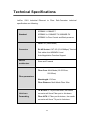
1
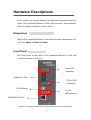
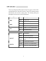
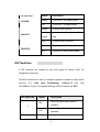
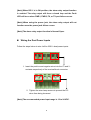
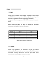
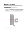
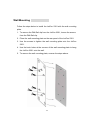
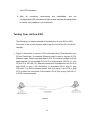
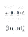
JetCon 2301 Industrial Ethernet to Fiber Rail Converter User’s Manual Rev 1.0 23-Dec-2004 Table of Contents Introduction......................................................... 1 Features ................................................................... 1 Link Lose Forwarding(LLF) .................................... 2 Package Checklist.................................................... 3 Hardware Descriptions ....................................... 4 Dimensions .............................................................. 4 Front Panel............................................................... 4 LED Indicators.......................................................... 5 DIP Switches............................................................ 6 Bottom View ............................................................. 7 Wiring the Dual Power Inputs ................................ 8 Wiring the Relay Output......................................... 9 Ports....................................................................... 10 TX Port................................................................. 10 FX Port................................................................. 10 Mounting Installation ........................................ 12 DIN-Rail Mounting.................................................. 12 Wall Mounting ........................................................ 14 Installation and Testing .................................... 15 Installing Your JetCon 2301 ................................... 15 Testing Your JetCon 2301 ..................................... 16 Trouble Shooting .............................................. 18 Technical Specifications................................... 19 Introduction JetCon 2301 Industrial Ethernet to Fiber Rail Converter is an entry-level and cost-effective solution for conversion between 10/100Base-TX and 100Base-FX. Specially designed for industrial applications, JetCon 2301’s dual power inputs offer a redundant power supply solution that secures your applications from power interruptions. JetCon 2301 has a built-in relay output function that sends alarm messages immediately when detecting any malfunction or disconnection of your system, allowing maintenance engineers to respond to any system failure in no time. JetCon 2301 has passed temperature, humidity, free fall, vibration, shock, EMI, and EMS tests, making it ideal for applications in harsh environments. JetCon 2301 Industrial Ethernet to Fiber Rail Converter brings you the most reliable data communication in any demanding industrial environment. Features 1. 10/100Base-TX to 100Base-FX multi mode media converter with a SC connector 2. Supports built-in Link Lose forwarding (LLF) 3. Supports dual DC power inputs, 12 to 48V, with a specially-designed DC adapter for office use 4. Relay output alarms for power failure and port break 5. 10/100Mbps, Full/Half-Duplex, MDI/MDI-X auto-sensing 6. Supports IEEE 802.3x flow control ¾ Flow control for full-duplex mode ¾ Back pressure for half-duplex mode 7. Supports wide operating temperature 1 Link Lose Forwarding(LLF) Link Lose Forwarding overcomes a problem that is often encountered when operating traditional media converters. With traditional media converters, what happens is that when one side of the connection fails, the other side still keeps sending packets to the disconnected side, and waits for responses that would never arrive. But with the built-in Link Lose Forwarding function, JetCon 2301 Industrial Ethernet to Fiber Rail Converter is able to disconnect the connection when any side of the connection fails, allowing the administrator to react promptly to system failures. 2 Package Checklist JetCon 2301 Industrial Ethernet to Fiber Rail Converters are packaged with the following items: JetCon 2301 Industrial Ethernet to Fiber Rail Converter One DIN-Rail Mounting Kit (screwed on your JetCon 2301) One Wall Mounting Kit (including one plate and six screws) Quick Installation Guide User’s Manual CD-ROM JetCon 2301 Industrial Ethernet to User’s Manual CD-ROM Quick Installation Guide Fiber Rail Converter Wall Mounting Plate Screws DIN-Rail Mounting Plate Contact your sales representative if any item is missing or damaged. 3 Hardware Descriptions In this section, we include hardware specifications and panel layouts of JetCon 2301 Industrial Ethernet to Fiber Rail Converter, and information of how to install and wire your JetCon 2301s. Dimensions JetCon 2301 Industrial Ethernet to Fiber Rail Converter’s dimensions (W x H x D) are 54mm x 135mm x 105mm. Front Panel The Front Panel of the JetCon 2301 Industrial Ethernet to Fiber Rail Converter is shown in Figure A. Power LED Indicators 100Base-FX Port FX Port LED Indicators DIP Switches TX Port LED Indicators 10/100Base-TX Port Figure A. Front Panel of JetCon 2301 Industrial Ethernet to Fiber Rail Converter 4 LED Indicators There are 8 diagnostic LEDs located on the Front panel of JetCon 2301 Industrial Ethernet to Fiber Rail Converter. These LED indicators provide administrators with real-time system status. The following table gives descriptions of the function of each LED indicator. Power LED Status Description Green Power is on. Off No power is supplied. Green Power is on. Off No power is supplied. Yellow Power, TX, or FX failure occurs. Off No failure is found. Status Description Green FX port’s link is active. Blinking FX port is transmitting or receiving Green data. Off FX port’s link is inactive. Orange FX port is in Full Duplex Mode. Off FX port is in Half Duplex Mode. PWR1 PWR2 Fault FX Port LED LNK/ACT HDX/FDX 5 TX Port LED Status Description Green TX port is in 100 Mbps Mode. Off TX port is in 10 Mbps Mode. Green TX port’s link is active. Blinking TX port is transmitting or receiving Green data. Off TX port’s link is inactive. Yellow TX port is in Full Duplex Mode. Off TX port is in Half Duplex Mode. 10/100M LNK/ACT HDX/FDX DIP Switches 4 DIP switches are located on the front panel of JetCon 2301 for configuration purpose. `` The DIP switches are used to configure operation modes for relay alarm function, LLF (Link Lose Forwarding), 100Base-FX port, 10/100Base-TX port. The default settings of DIP switches are OFF. DIP Switch No Status ON 1 OFF 2 ON Description Fault LED and Relay Alarm is enabled. Fault LED and Relay Alarm is disabled. LLF is enabled. 6 and OFF LLF is disabled. ON FX port is in Full Duplex Mode. OFF FX port is in Half Duplex Mode. 3 ON 4 OFF TX port is in 100 Mbps Full Duplex Mode. TX port is in Auto-Negotiation Mode. [Note] Before you make any changes to DIP switch settings, make sure that the power has been turned OFF. [Note] When you enable Link Lose Forwarding function, make sure that you enable both JetCon 2301s in a pair. Use DIP-2 on both JetCon 2301s to enable the LLF function. Bottom View The bottom view of the JetCon 2301 Industrial Ethernet to Fiber Rail Converter consists of one terminal block connector with two DC power inputs (PWR1, PWR2), one relay contact, and one DC IN power jack. Figure B. Bottom View of JetCon 2301 Industrial Ethernet to Fiber Rail Converter 7 [Note] When DIP-1 is in ON position, the alarm relay output function is enabled. The relay output will form a closed loop and the Fault LED will be on when PWR1, PWR2, FX, or TX port failure occurs. [Note] When using the power jack, the alarm relay output will not function once the power jack failure occurs. [Note] The alarm relay output function is Normal Open. Wiring the Dual Power Inputs Follow the steps below to wire JetCon 2301’s dual power inputs. V- V+ V- V+ 1. Insert the positive and negative wires into the V+ and Vcontacts respectively of the terminal block connector. 2. Tighten the wire-clamp screws to prevent the DC wires from being loosened. [Note] The recommended power input range is 12 to 24 VDC. 8 Wiring the Relay Output The fault relay alarm contacts are the two contacts located in the middle of the terminal block connector. By inserting the wires to these contacts and setting the DIP-1 to ON position, the alarm relay output function will detect any power or port failure, and form a Short circuit. The alarm relay output is “Normal Open”. See figure C. 1A@24V Insert the wires into the fault alarm contact Figure C. Fault Relay Block Diagram 9 Ports TX Port JetCon 2301’s 10/100Base-TX port supports 10/100Mbps, Full/Half-Duplex, and MDI/MDI-X auto-sensing. JetCon 2301 can adjust the operating modes according to the attached devices. Users need not change any configuration. The pin assignments of MDI-X/MDI is described in the table below. [Note] Cables used here are those of Category 5, with RJ45 connectors and length of less than 100 meters. Pin No. MDI-X MDI 1 RD+ TD+ 2 RD- TD- 3 TD+ RD+ 6 TD- RD- Table 1. MDI-X, MDI pin assignments FX Port JetCon 2301’s 100Base-FX port connector is SC type and supports multi-mode fiber. To connect the fiber port on your JetCon 2301 to another one located on another JetCon 2301, follow the figure below. Wrong connection will cause fiber ports not to work normally. 10 [Note] Cables used here are those of 50/125 or 62.5/125 um multi-mode fiber SC connectors with length of less than 2km. Figure D 11 Mounting Installation DIN-Rail Mounting The DIN-Rail clip is already attached to the JetCon 2301 when packaged. If the DIN-Rail clip is not screwed on the JetCon 2301, follow the instructions and the figure below to attach the DIN-Rail clip to the JetCon 2301. Figure E 1. Use the screws to attach the DIN-Rail clip to the rear panel of the JetCon 2301. 2. To remove the DIN-Rail clip, reverse step 1. 12 Follow the steps below to mount the JetCon 2301 to the DIN-Rail track. 1. First, insert the upper end of the DIN-Rail clip into the back of the DIN-Rail track from its upper side. 2. Lightly push the bottom of the DIN-Rail clip into the track. 3. Check if the DIN-Rail clip is tightly attached on the track. 4. To remove the JetCon 2301 from the track, reverse the steps above. 13 Wall Mounting Follow the steps below to install the JetCon 2301 with the wall mounting plate. 1. To remove the DIN-Rail clip from the JetCon 2301, loosen the screws from the DIN-Rail clip. 2. Place the wall mounting plate on the rear panel of the JetCon 2301. 3. Use the screws to tighten the wall mounting plate onto the JetCon 2301. 4. Use the hook holes at the corners of the wall mounting plate to hang the JetCon 2301 onto the wall. 5. To remove the wall mounting plate, reverse the steps above. 14 Installation and Testing In this section, we will describe how to install your JetCon 2301 and how to test your system. Installing Your JetCon 2301 1. Take your JetCon 2301 Industrial Ethernet Rail Converter out of the package box. 2. Check if the DIN-Rail clip is attached to the JetCon 2301. If the DIN-Rail clip is not attached to the JetCon 2301, refer to DIN-Rail Mounting section for DIN-Rail installation. If you want to wall-mount the JetCon 2301, refer to Wall Mounting section for wall mounting installation. 3. Power on the JetCon 2301. Refer to the Wiring the Dual Power Inputs section for wiring instructions. After the JetCon 2301 is powered on, the power LED on the JetCon 2301 will light up. Refer to the LED Indicators section for descriptions of the function of each LED indicators. 4. Connect one side of an Ethernet cable into the JetCon 2301’s TX port, while the other side is connected to the attached device. The LED will light up when the cable is correctly connected. Refer to the LED Indicators section for descriptions of the function of each LED indicators. 5. Connect one side of a fiber cable into the JetCon 2301’s FX port, and the other side to the other JetCon 2301 in this pair. The fiber port LED on the JetCon 2301s will light up when the cable is correctly connected. Refer to the LED Indicators section for descriptions of the function of 15 each LED indicators. 6. After all necessary connections are established, and the corresponding LED indicators all light up and indicate that each status is normal, the installation is now finished. Testing Your JetCon 2301 The following is a simple example to illustrate how to use JetCon 2301 Converter to set up your system, and to test if your JetCon 2301 functions normally. 1. Figure F shows how to connect 2 PCs with each other (This step tests your PC and Cable line). A crossover Ethernet cable is used to connect 2 PCs’ Ethernet cards. Please note that these 2 PCs’ IPs must be configured in the same network (in our example, PC-A’s IP is configured as 192.168.1.1, and PC-B’s IP is 192.168.1.2). After the connection is established, use PC-A to ping PC-B to see if the connection is successful.(PC-A: Key in ping 192.168.1.2 in DOS command mode) And vice versa. Use PC-B to ping PC-A to see if the connection is successful. (PC-A: Key in ping 192.168.1.1 in DOS command mode) Figure F. 16 2. Follow the instructions described in the previous section to add 2 JetCon 2301 to the system illustrated in Figure F. Use a fiber cable to connect the JetCon2301s, and use Ethernet cables to connect the PCs and the JetCon 2301, as shown in Figure G. After finishing connecting PCs and JetCons 2301, use PC-A to ping PC-B to see if the connection is successful. The result should be the same with the one from step 1. You can also use PC-B to ping PC-A. Figure G. 3. Your system might also resemble the system shown in Figure H. A switch is used to connect between a JetCon 2301 and a PC. Try to ping the PC(s) located on the other side of the JetCon2301. Please note that every PC’s IP needs to be configured in the same network (as step 1). If you can ping the PC located on the other side of JetCon 2301, then your JetCon 2301 functions normally. Figure H. 17 Trouble Shooting Make sure you are using the correct DC power suppliers (12 to 48 VDC) or power adapters. Do not use power adapters with DC output over 48V. It will damage devices. Select proper cables for TX port and FX port to set up your network. Make sure you are using the correct cables. If the LED indicators on the JetCon 2301 are normal, and cables are correctly connected, but packets are not being transmitted, check the Ethernet devices in your system for configurations or status. 18 Technical Specifications JetCon 2301 Industrial Ethernet to Fiber Rail-Converter technical specification are following. IEEE802.3 10BASE-T Standard IEEE802.3u 100BASE-TX/100BASE-FX IEEE802.3x Flow Control and Back pressure Fiber: SC (Multi-Mode) Connector RJ-45 Socket: CAT-3/5 (10/100Mbps) Twisted Pair cable Auto MDI/MDI-X and Auto-Negotiation Function Support Switch architecture Store and Forward Fiber Core: Multi-Mode (62.5/125um, 50/125um) Fiber parameters Wavelength: 1310nm Fiber Distance: Multi-Mode Fiber 2Km TX ÎFiber: If TX port link down, the media Link Lose converter will force Fiber port to link down Forwarding Fiber ÎTX: If Fiber port link down, the media converter will force TX port to link down. 19 DIP Switch 1: ON: Enables Port Alarm OFF: Disables Port Alarm DIP Switch 2: ON: Enables LLF (Link Lose Forwarding) DIP Switch OFF: Disables LLF (Link Lose Forwarding) DIP Switch 3: ON: 100Base-FX Half Duplex mode OFF: 100Base-FX Full Duplex mode DIP Switch 4: ON: 100Base-TX Full-duplex mode OFF: Auto-Negotiation PWR1 (Green), PWR2 (Green), FAULT(Yellow) Fiber: LNK/ACT (Green) HDX/FDX(Orange) LED TX: 10/100M(Green) LNK/ACT (Green) HDX/FDX(Orange) Power Power consumption Reserve polarity protection Overload current protection Operation Temperature Storage Temperature Input Voltage: 12 to 48VDC; Redundant inputs 4.6 Watts Present Present 0 to 60°C (32 to 140°F) -40 to 85°C (-40 to 85°F) 20 Ambient Relative Humidity Dimension 5 to 90%(non-condensing) 54 mm (W) x 135 mm (H) x 105mm (D) EMI FCC Class A EMS EMI and EMS CE EN6100-4-2 CE EN6100-4-3 CE EN-6100-4-4 CE EN6100-4-5 CE EN6100-4-6 Safety UL, cUL, CE/EN60950 Shock IEC 60068-2-27 Free fall IEC 60068-2-32 Vibration IEC 60068-2-6 21