1
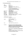
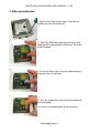
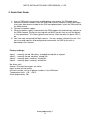
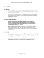
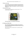
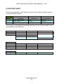
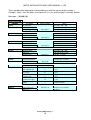
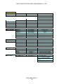
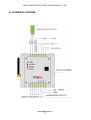
Metis
GSM ALARM MONITORING
AND
CONTROL SYSTEM
INSTALLATION AND USER MANUAL
V2.2E 14.8.2007
Global Safety & Security Solutions Oy
www.globalsafety.fi
METIS INSTALLATION AND USER MANUAL v 2.2E
1. Technical specification .................................................................................................3
2. SIM-card installation......................................................................................................4
3. Quick Start Guide...........................................................................................................5
4.0 Installation....................................................................................................................6
4.1 SIM-card.....................................................................................................................6
4.2 Power supply and battery...........................................................................................6
4.3 Start Up ......................................................................................................................6
4.4 Installation of the alarm inputs...................................................................................7
4.5 Outputs......................................................................................................................7
4.6 Power connections for detectors ...............................................................................8
4.7 Arm / Disarm and indication ......................................................................................8
4.8 Basic selections.........................................................................................................8
4.9 Factory settings .........................................................................................................9
4.10 Temperature detector...............................................................................................9
5. Operation........................................................................................................................9
5.1 Phone numbers .........................................................................................................9
5.2 Normally open or normally closed input ....................................................................9
5.3 Delays and Arm/Disarm commands ..........................................................................9
5.4 Measurements.........................................................................................................10
5.5 Alarm call ................................................................................................................10
5.6 Lock-Up feature.......................................................................................................10
5.7 Log ..........................................................................................................................10
6. Indications, control commands and status inquiries ...............................................11
6.1 Indications ...............................................................................................................11
6.2 Control commands ..................................................................................................11
6.3 Status inquiries........................................................................................................11
7. Configuration with SMS ..............................................................................................12
7.1 Settings ....................................................................................................................12
7.2 Alarm texts ...............................................................................................................12
7.3 Phone numbers........................................................................................................12
7.4 Inputs’ parameters....................................................................................................12
7.5 Upper and lower limits for the temperature sensor...................................................12
7.6 Intervals for automatic transmission and logging......................................................12
7.7 Phone number grouping...........................................................................................12
7.8 Alarm (siren) output..................................................................................................13
7.9 Restoring factory settings.........................................................................................13
8.0 Settings with Metis-Soft ...........................................................................................13
9.0 SETTING CHART........................................................................................................14
10. SCHEMATIC DIAGRAM .............................................................................................17
www.globalsafety.fi
2
METIS INSTALLATION AND USER MANUAL v 2.2E
1. Technical specification
Type
Firmware
GSM-modem
Interfaces
GSM-antenna
Size
Connectors
Gard reader
Indication
Data transfer
Power supply
Consumption
Metis 1.0
from 7.7a
Siemens MC55
900/1800 dual band GSM / GPRS, FTA
4 digital inputs
Arm / disarm switch, configurable for inputs 1-4
one remote controlled output relay
one alarm relay for local alarm indication
one input for a digital temperature detector
ARMED output
dual band 900/1800
100 x 85 x 35 mm
Screw connectors for inputs/outputs
Small SIM-card (3V), all operators
4 indication LEDs
SMS, phone call, RS-232, GSM-data
Suggested power type 12...28VDC / 1A , regulated
40 mA average / 400 ma peak
Temperature area -20...+50°C
Delivery package Metis device
Installation and user manual
Options
Temperature detector
Power supply / Battery charger
Battery
Enclosures
External antennas
Sales
Global Safety & Security Solutions Oy
Limitations
This device has not been designed, intended or
inspected to be used in any life support related
application nor as a part of any other critical system.
This device cannot be used in such conditions where
its erroneous function can cause danger.
When the device is used for burglar alarm applications all
requirements and instructions of the authorities must be
considered.
230V mains voltage installations can only be done by
an authorized installation company.
www.globalsafety.fi
3
METIS INSTALLATION AND USER MANUAL v 2.2E
2. SIM-card installation
1. Loosen the fixing screws (4pcs) and take the
module out from the enclosure.
2. Open the SIM-card cradle by pushing a metal
glider gently as presented in the picture. Raise the
cradle upwards.
3. Install the SIM-card so that the sloped footing is
outwards like in the picture.
4. Push the cradle down and close the reader with
the metal glider.
You can fix the module back to the enclosure.
www.globalsafety.fi
4
METIS INSTALLATION AND USER MANUAL v 2.2E
3. Quick Start Guide
1. Insert a SIM-card in to your own mobile phone and remove the PIN-code query.
2. Remove all phone numbers from the SIM-card and also remove all SMS-messages.
Insert your own phone number to the SIM-card phone book. Insert the SIM-card into
the Metis-device.
3. Connect the power supply.
4. When the power supply is connected, the GSM modem will automatically register to
the GSM-network. During the start-up the red WAIT-led will stay on until the device
is fully operational. This takes typically one minute. After that only the green LED is
on.
5. You have now started up the Metis-device . You can receive info from the unit. You
can also send inquiries and configuration commands via SMS to the unit as
described in this manual.
Factory settings:
Input 1 :
Input 2 :
Input 3 :
Input 4 :
normally closed, 30s delay, armed/disarmed with a keypad
normally closed, no delay, armed 24h
normally open, no delay, armed 24h
normally open, no delay, armed 24h
No Alarm calls.
Armed / Disarmed messages are active.
Input restore info not active.
All alarms will be sent to all phone numbers in the SIM-card.
Temperature limits +10….+30°C
Alarm output delay 20s
www.globalsafety.fi
5
METIS INSTALLATION AND USER MANUAL v 2.2E
4.0 Installation
4.1 SIM-card
All standard SIM-cards can be used. Before the SIM-card installation put the
card into your own mobile phone and remove the PIN-code request, all phone
numbers and text messages.
You can enter your phone number to the SIM-card with your mobile phone.
Please check that the number is really stored to the SIM-card and not to the
mobile phone’s memory.
4.2 Power supply and battery
All main connections are described in appendix 1 at the end of this
manual. The external power supply connectors are on the down right
corner of the pc-board. With standard configuration it is possible to use a
regulated power supply of 12...28 VDC
When the power supply voltage is lower than 11,0V the unit will send an
SMS-message “Battery Low”. This message will also indicate a mains
voltage break after a few hours in such systems where an external battery
backup is used.
4.3 Start Up
When the power supply is connected the GSM modem will automatically register
to the GSM-network. During the start-up the red WAIT-led will stay on until the
device is fully operational. This takes typically two minutes. After that only the
green LED is on.
If the temperature detector is connected during the start-up the unit will
automatically start measuring and observing the temperature limits.
www.globalsafety.fi
6
METIS INSTALLATION AND USER MANUAL v 2.2E
4.4 Installation of the alarm inputs
All input connections are described in appendix 1 at the end of this
manual.
To test the inputs close the Z1 and Z2 with short wires and after the startup remove them. The red ALARM-led indicates an alarm when the wires
are removed and a corresponding SMS-message will be sent. Please
note that SMS messaging will take some time and you may have to wait
the response for a while. Remember that with factory settings input 1 has
a 30s delay but the other inputs don´t.
After testing, connect detectors or any voltage free contact like a burglar
alarm centre to the input input connectors. It is recommend to connect all
door switches and movement detectors to input 1. Therewith it will be
possible to control the status of the input 1 by armed / disarmed switch
(or keyboard / card reader etc).
4.5 Outputs
There are two relays on the printed circuit board. These can be used to
control external devices. Maximum load for these relays is 24VDC/1A.
Note! In any circumstances do not connect 230VAC voltage to the
device. It might cause danger of life or fire.
For higher loads please use external relays. It is also recommended to
use a diode over the coil of the external relay to prevent harmful
transients.
Relay functions:
ALARM
This is an alarm relay. It can be used to control a local
alarm indication device like an outdoor siren.
Relay 1
Can be controlled by two different ways depending on the
configuration.
If the factory settings are valid this relay is controlled by
SMS. If a phone call control is valid the relay gives a 5s
pulse each time the device receives a standard phone call
from one of the numbers in the SIM-card.
www.globalsafety.fi
7
METIS INSTALLATION AND USER MANUAL v 2.2E
4.6 Power connections for detectors
All external active detectors must have a power lines connected directly to
an external power supply. All power lines must be protected with a fuse.
4.7 Arm / Disarm and indication
It is possible to use external keypads, card readers etc to arm or disarm
the Metis-unit. You can also specify which inputs will follow this arming /
disarming.
It is possible to select the type of arm / disarm input signal between solid
state and pulse control. When solid state is selected the device will
change the status each time the Z5 input changes state (e.g. key operated
switch).
When pulse control is selected the device will change the status each time
Z5 input is connected to GND for two seconds making possible to use
pulse control (e.g. keypad or a card reader with a pulse control).
In addition to the abovementioned methods it is also possible to control
the device with your mobile phone. In this case the unit is armed /
disarmed by calling to the device’s number (See
It is possible to connect a led-indicator to Stat output to indicate existing
arm/disarm status. Max current for this open collector output is 50mA.
4.8 Basic selections
With a special SMS-command (06=) is possible to configure some basic
functions of the Metis-device :
A complete list of functions are attached in the appendix 1.
Most of the configuration is normally made by SMS and it is possible only
with the entry 1 number in the SIM-card. If the jumper J1 is installed these
commands are possible for all phone numbers regardless if those are in
the SIM-card or not.
This so called “service phone” feature is intended only to assist
during the installation. The jumper J7 should always be removed
when the device is in use.
www.globalsafety.fi
8
METIS INSTALLATION AND USER MANUAL v 2.2E
4.9 Factory settings
If the jumper J2 is installed during the start-up all factory settings are
restored. This might help installation when the former settings are not
known.
4.10 Temperature detector
A temperature detector can be connected with three wires directly to the
connector (please refer Appendix 1) or it can be wired max 10 m away
from the device. In moist conditions like outdoors an encapsulated
temperature detector must be used.
A setup-SMS enables to adjust the limit values to the temperature
detection. If the temperature goes out of the permitted range the device
will send an alarm. The device will also inform when the temperature
returns into the permitted range.
5. Operation
5.1 Phone numbers
The unit uses a SIM-card as a phone book. You can see the numbers and
even modify them with your own mobile phone. First number in the list is
the master number. From this phone it is possible to give all listed
commands and inquiries including all setting commands.
All other numbers (2-15) in the SIM-card will receive alarms and it is
possible to make status inquiries and relay commands but it is not
possible to change settings.
5.2 Normally open or normally closed input
With a configuration command it is possible to select the input connection
type ( normally open or normally closed ).
5.3 Delays and Arm/Disarm commands
If the armed/disarmed switch is closed during the delay the device will not
send an alarm from input 1. When the switch is opened again the user
has 30s delay time to leave the secured area. It is possible to adjust this
delay time between 00...99s .
It is also possible to define delays for inputs 2,3 and 4. However these
delays are different from the one, used with the input 1. For inputs 2-4 the
delay means time how long the detector must be in the alarm status
before the alarm is indicated. This is not normally used in security
systems.
It is possible to define which inputs will be bypassed with arm/disarm
input. All other inputs are 24h inputs for continuous detector monitoring.
Arm / Disarm commands can also be done with a mobile phone. When the
unit receives a phone call from one of the numbers in the SIM-card and
jumper J1 is installed the arm/disarm status will change. The unit does not
www.globalsafety.fi
9
METIS INSTALLATION AND USER MANUAL v 2.2E
5.4 Measurements
It is possible to connect a digital temperature sensor to the unit and
specify upper and lower limits for it. If the temperature goes out of the
permitted range the device will send an alarm. The device will also inform
when the temperature returns back into the range.
Possible settings for the temperature input are:
Upper limit, lower limit, time interval between measurements, timer based
SMS-sending or data logging into the memory
5.5 Alarm call
It is possible to configure the device to make a phone call after SMS.
When the phone call option is in use it is possible to interrupt the alarm
sequence by making an alarm call to the device. This call will reset all the
alarms and restore the device to the normal mode.
5.6 Lock-Up feature
The device has a function to prevent unnecessary phone bill costs. If an
alarm is indicated more than five times in an hour the device will stop
sending alarms. This lock up can be restored by calling the device from
one of the phone numbers stored in the SIM-cards memory.
If the user does not restore the device it will be automatically restored to
normal mode after six hours.
5.7 Log
The unit has an event log function. All events are stored to a specific
memory with a time stamp. The log search is possible with a Metis-Soft
program via GSM-data connection.
The log contents 1000 latest events.
www.globalsafety.fi
10
METIS INSTALLATION AND USER MANUAL v 2.2E
6. Indications, control commands and status inquiries
It is possible to make status inquiries and send commands to control the
device with SMS. The actual command is two numbers between brackets.
You can store a command into your own phone and write help text
before/after the command like temperature inquiry (41). The text outside
the brackets does not affect the operation.
6.1 Indications
Input 1 alarm / restored
Input 2 alarm / restored
Input 3 alarm / restored
Input 4 alarm / restored
Armed / Disarmed
Temperature alarm / restored
Battery low
Timer sendings
6.2 Control commands
Relay 1 off / on constantly
Relay 1 on for 5 sec
Relay 1 on for n min (values n= 1…999min)
6.3 Status inquiries
It is possible to ask the status of the device by sending a text message.
The format is similar to the control commands. The answer will arrive as
an SMS after a little while.
Possible inquiries:
Temperature value inquiry
Input status inquiry
Outputs status inquiry
www.globalsafety.fi
11
METIS INSTALLATION AND USER MANUAL v 2.2E
7. Configuration with SMS
7.1 Settings
It is possible to send commands to control the device with SMS. The
actual command is two numbers between brackets.
Note that all configuration commands are possible only with the ”master”
phone number (entry 1 in the SIM card ).
The actual commands are represented inside brackets Text outside the brackets
don’t have any effect on the functionality but it can help to remember what the
command is about; For example saving a message to one’s mobile phone
saying ”Turn relay on (11)” is much clearer than simply ”(11)”.
7.2 Alarm texts
The alarm texts can be set freely. Note that the maximum length for the
message is 32 characters!
7.3 Phone numbers
A total of 15 alarm message receiving numbers can be programmed to
Metis.
7.4 Inputs’ parameters
There are several parameters affecting input functioning, such as delay,
direction of detection and backup call.
7.5 Upper and lower limits for the temperature sensor
The temperature detector alerts if set limits are broken. The factory setting
for the limits is: lower limit -10°C and upper limit +30°C. The measuring
range for the temperature detector is -55°C to +99°C.
7.6 Intervals for automatic transmission and logging
Metis can be set to either send or save into log temperature measurement
values in desired intervals (0-99 hours).
7.7 Phone number grouping
Although Metis sends alarms to all sotred numbers by default it is possible
to define which alarms are delivered to which numbers. This is especially
useful in situations where for example different events causing the alarm
require different persons to take action.
www.globalsafety.fi
12
METIS INSTALLATION AND USER MANUAL v 2.2E
7.8 Alarm (siren) output
The siren output can be set to activate during alarm for desired amount of
time (either 20 seconds (default), or 1-9 minutes). The alarm events that
trigger the siren output can also be defined. If for example the alarms from
inputs 1 & 3 are to trigger the alarm output for 3 minutes the setting would
be (89=3,1,3).
7.9 Restoring factory settings
Factory settings can be restored by connecting the jumper “J2” and
cycling the power on and off.
Note that the jumper J1 must always be disconnected!
8.0 Settings with Metis-Soft
With a special Metis-Soft package it is possible to connect a PC to the
device. The package includes a connection cable and a software CD. The
software can be used to set parameters into the device and to transfer log
from the device to the PC.
With an external modem connected to the pc it is possible to remotely
control the device.
www.globalsafety.fi
13
METIS INSTALLATION AND USER MANUAL v 2.2E
9.0 SETTING CHART
Part of the configuration is possible by connecting small jumpers between two pins
in the printed cirquit board.
SELECTION
JUMPER
1
2
3
FUNCTION
service phone function
factory settings
INSTALLED
in use
restoring
NOT INSTALLED
not in use
normal use
It is possible to send following commands and inquiries from all the numbers which
are recorded into the SIM-card.
CONTROLS
Relay commands
FUNCTION
Relay 1
off
on
5s pulse
timer function
Inquiries
Temperature
Input status
Outputs
value
status
status
SMS FORMAT
(10)
(11)
(31)
(31=5)
(41)
(42)
(43)
www.globalsafety.fi
14
INFO
lenght 5s
duration 1…999 minutes
SMS, centigrades
SMS, all inputs
SMS
METIS INSTALLATION AND USER MANUAL v 2.2E
These configuration commands are possible only from the master phone number !
Example : Input 1 has 30s delay, the alarm call is in use and the input is normally closed.
Message: ( 01=30,1,0 )
CONFIGURATION
TARGET
SETTINGS
Input 1
in / out delay
alarm call
detector type
Input 2
Input 3
Input 4
Temperature
sensor
detector delay
alarm call
detector type
detector delay
alarm call
detector type
detector delay
alarm call
detector type
measuring interval
alarm call
Basic settings
(01=aa,b,c)
INFO
aa= delay , 00…99s
b=0=no call, b=1=call
c=0=NC, c=1=NO
(02=aa,b,c)
aa= delay , 00…99s
b=0=no call, b=1=call
c=0=NC, c=1=NO
(03=aa,b,c)
aa= delay , 00…99s
b=0=no call, b=1=call
c=0=NC, c=1=NO
(04=aa,b,c)
aa= delay , 00…99s
b=0=no call, b=1=call
c=0=NC, c=1=NO
(05=aa,b)
(06=abcde)
armed/disarmed
with a phone call
armed/disarmed
messages
relay 2 controlled by
a phone call
restore messages
bypass with a local
switch
Bypass
SMS-FORMAT
bypassed inputs
always on
a
b
c
d
e
(09=a,b,c,d)
www.globalsafety.fi
15
aa=interval in seconds
b =0= no call, b=1= call
0=not in use, 1=in use
0=no
1=yes
0=no
1=yes
0=no
1=yes
0= no sendings
1= yes
0=pulse control
1=switch control
list of by-passed inputs
all others
METIS INSTALLATION AND USER MANUAL v 2.2E
CONFIGURATION
TARGET
SETTINGS
Limit values
temperature
SMS-FORMAT
(50=aa,bb)
INFO
aa= low, bb=high, centigrades
Example (50=+10,+35)
Please use signs!
Automatic
sendings
temperature
(55=aa,0)
aa= interval 00…99h
Automatic
recording
temperature
(55=aa,1)
aa= interval 00…99h
Phone numbers
Number 1
Number 2
Number 3
Number 4
--Number 15
(91=+35840...)
(92=+35840...)
(93=+35840...)
(94=+35840...)
(95=+35840...)
(915=+35840...)
master, user 1
user 2
user 3
user 4
user 5
user 15
Grouping
( examples )
Input 1
Input 2
Input 3
Input 4
Temperature
(61=1,2,3...)
(62=1,3,5...)
(63=2)
(64=1,2)
(65=1,8)
sent to numbers 1,2,3
sent to numbers 1,3,5
sent to number 2
sent to numbers 1, 2
sent gto numbers 1 and 8
Alarm text
Input 1
Input 2
Input 3
Input 4
(81=abc...)
(82=abc...)
(83=abc...)
(84=abc...)
Input 1 message (SMS)
Input 2 message (SMS)
Input 3 message (SMS)
Input 4 message (SMS)
Alarm output
for outdoor siren
(89=a,b,b,b....)
www.globalsafety.fi
16
a = 0 means 20s
aa= 1…9 = delay in minutes
b=inputs which control the
relay1
Example. (89=2,1,2,3)
METIS INSTALLATION AND USER MANUAL v 2.2E
10. SCHEMATIC DIAGRAM
www.globalsafety.fi
17