1
PARTS & SERVICE
MANUAL
Part Number: 513868-200
March 2013
Serial Number TL49-01-008562 and after.
TL49J
ENGLISH
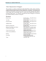
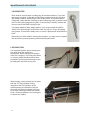
When contacting Snorkel for service or parts information, be sure to include the MODEL and SERIAL
NUMBERS from the equipment nameplate. Should the nameplate be missing, the SERIAL NUMBER
is also stamped on top of the chassis bhind the toe hitch.
MANUFACTURER
TANFIELD POWERED ACCESS LTD.
SNORKEL IS A TRADING DIVISION OF:
TYPE APPROVAL e11*2007/46*0879
TANFIELD POWERED ACCESS LTD.
VIGO CENTRE, BIRTLEY ROAD,
WASHINGTON,
TYNE & WEAR, U.K.
T: +44 (0)845 1550 057
VIN
Kg
TYPE
0-
Kg
VARIANT
1-
Kg
SER NR
MAX GROSS WT
MAX AXLE WT
YEAR
PART No: 508945-004
Snorkel,
Vigo Centre, Birtley Road,
Washington, Tyne & Wear,
NE38 9DA, U.K.
MODEL
NUMBER
SERIAL
NUMBER
TL49J BI ENERGY
MONTH / YEAR
OF MANUFACTURE
SLOPE SENSOR ALARM SETTING
NON-LOADED
MACHINE
WEIGHT
------------2300
lbs
kg
ENGINE
POWERED
MODELS
------------N/A
hp
kW
MAXIMUM
OUTRIGGER
LOAD
------------1320
lbs
kg
MAXIMUM
GRADEABILITY
N/A
Indoors
MAXIMUM
ALLOWABLE
MANUAL FORCE ------400
(SIDE PULL)
MAXIMUM
PLATFORM
HEIGHT
RATED NUMBER
OF OCCUPANTS
FRONT
TO BACK
------- lbs
400 N
------------15.0
ft
m
Indoors
Outdoors
2
2
ASSEMBLED IN
SIDE
TO SIDE
N/A deg
------------N/A
BATTERY
POWERED
MODELS
lbs
kg
DRIVE
MOTORS
N/A
V
BATTERIES
24
310
V
Ah
CHARGER
INPUT
%
Outdoors
N/A deg
MAXIMUM
WHEEL
LOAD
110/220
V
MAXIMUM
ALLOWABLE
WIND SPEED
------------12.5
mph
m/s
MAXIMUM
PLATFORM
REACH
------------9.10
ft
m
MAXIMUM
DRIVE
HEIGHT
------------N/A
ft
m
MAXIMUM 200kg = 2 Persons
PLATFORM
+ 40kg Tools
LOAD
CAUTION
ONLY trained and authorised personnel may operate this machine.Consult the Operation Manual before using this machine.
DO NOT make any changes to this machine, any changes made will invalidate the manufactures warranty and
may contravene legislation.
Axle weights with machine in the stowed position.
STEER AXLE
kg
100
------------- lbs
DRIVE AXLE
-------------
lbs
2200
Serial number stamped on chassis behind the
Number Plate.
kg
511039-300
www.snorkellifts.com
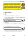
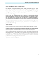
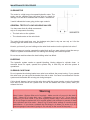
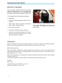
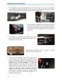
SAFETY NOTICE
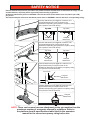
Harness attachment points are provided in the platform and the manufacturer recommends the usage of a fall
restraint harness, especially where required by national safety regulations.
All harness attachment points on SNORKEL vehicles have been tested with a force of 3,650 lbs (16.3 KN)
per person.
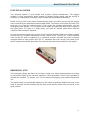
See below examples of harness attachment points used on SNORKEL vehicles with their corrosponding rating;
Harness attachment point Type 1. is rated for one
lanyard attachment per loop as shown in the
illustrations depending upon platform occupancy rating
(see operators manual & decals).
Type 1.
Top View
Top View
2 lanyard
attachments
1 lanyard
attachment
Harness attachment point Type 2. is rated for two
lanyard attachments per loop as shown in the
illustrations depending upon platform occupancy rating
(see operators manual & decals).
Type 2.
Top View
Top View
2 lanyard
attachments
1 lanyard
attachment
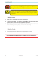
Harness attachment point Type 3. is rated for one
lanyard attachment per loop as shown in the
illustrations depending upon platform occupancy rating
(see operators manual & decals).
Front View
1 lanyard
attachment
Type 3.
Harness attachment point Type 4. is rated for one
lanyard attachment per loop as shown in the
illustrations depending upon platform occupancy rating
(see operators manual & decals).
1 lanyard
attachment
Type 4.
NOTE: There can be more harness attachment points per machine than the
maximum number of occupants allowed in a platform. Refer to
the platform decal & specifications table listed in the operators
manual for the correct occupancy rating before use.
OPERATORS MANUAL
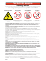
Safety Rules
All personnel shall carefully read, understand and follow all safety rules and operating instructions
before operating or performing maintenance on any SNORKEL aerial work platform
Electrocution Hazard
Tip Over Hazard
Collision Hazard
Fall Hazard
This Machine is NOT
Insulated
NEVER elevate the platform or drive the
machine while elevated unless the machine is
on a firm, level surface.
NEVER position the platform without
first checking for overhead obstructions
or other hazards.
NEVER climb, stand, or sit on platform
guardrails or midrail.
USE OF THE AERIAL WORK PLATFORM: This aerial work platform is intended to lift persons and his tools as
well as the material used for the job. It is designed for repair and assembly jobs and assignments at overhead
workplaces (ceilings, cranes, roof structures, buildings etc.). All other uses of the aerial work platform are
prohibited!
THIS AERIAL WORK PLATFORM IS NOT INSULATED! For this reason it is imperative to keep a safe distance
from live parts of electrical equipment!
is prohibited! See “Special Limitations” for details.
The use and operation of the aerial work platform as a lifting tool or a crane (lifting of loads from below upwards or
from up high on down) is prohibited!
NEVER exceed the manual force allowed for this machine. See “Special Limitations” for details.
DISTRIBUTE all platform loads evenly on the platform.
NEVER
"
bumps, curbs, or debris; and avoiding them.
OPERATE machine only on surfaces capable of supporting wheel loads.
NEVER operate the machine when wind speeds exceed this machine’s wind rating. See “Beaufort Scale” for
details.
IN CASE OF EMERGENCY push EMERGENCY STOP switch to deactivate all powered functions.
IF ALARM SOUNDS#$%'*/
surface.
Climbing up the railing of the platform, standing on or stepping from the platform onto buildings, steel or prefab
concrete structures, etc., is prohibited!
Dismantling the swing gate or other railing components is prohibited! Always make certain that the swing
gate is closed and securely locked!
It is prohibited
3
"6
<
To extend the height or the range by placing of ladders, scaffolds or similar devices on the platform is prohibited!
NEVER perform service on machine while platform is elevated without blocking elevating assembly.
INSPECT the machine thoroughly for cracked welds, loose or missing hardware, hydraulic leaks, loose wire
connections, and damaged cables or hoses before using.
VERIFY that all labels are in place and legible before using.
NEVER use a machine that is damaged, not functioning properly, or has damaged or missing labels.
To bypass any safety equipment is prohibited and presents a danger for the persons on the aerial work platform
and in its working range.
NEVER
=*>
*
/
are prohibited or permissible only at the approval by SNORKEL.
AFTER USE, secure the work platform from unauthorized use by turning both keyswitches off and removing key.
TL49J
513868-000
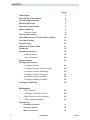
CONTENTS
Page
Introduction
3
Description of Equipment
4
Working Envelope
6
Operator Requirements
7
Warning Notices
8
. Beaufort Scale
9
Towing Instructions
10
Hand Manoeuvring (Friction Drive Option)
12
Pre-Start Checks
13
Power Supply
19
Batteries, & Power Pack
15
Setting Up
16
Extending Structure
18
. Basket Controls
18
. Ground Controls
20
Safety Harness
21
Emergency Controls
. Emergency Stops
21
. Emergency Lower (Electronically)
22
. Emergency Lower (Manually)
23
. Emergency Raise Outriggers
24
. Emergency Cage Overload
24
. Emergency Battery Isolation
25
Stowing the Machine
26
Maintenance
. Daily Checks
27
. Weekly and Monthly Checks
28
. Slew Drive and Limit Switches
29
. Trailer Lighting Diagram
30
Appendices
2
Petrol/Bi-fuel Option.
31
Generator Option.
32
Mains connection.
33
513868-000
TL49J
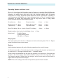
INTRODUCTION
The SNORKEL TL49J is a class leader, offering several features as standard that other
manufacturers only provide as optional extras.
These include powered basket rotation and fully proportional hydraulic controls, at both basket
and ground level.
$=?@JQXZ#
[JQXZ#
vital for working in tight spaces.
SNORKEL Powered Access has a global reputation for innovation and a proud heritage in the
design and manufacture of high quality powered access equipment.
The company was founded in the US more than 65 years ago, on the principle of constantly
improving service excellence for end users.
Every model in our growing range of versatile, trailer mounted units is a class leader and
together they have set new industry benchmarks.
% ]^JJJJ_ and support capacity, mean SNORKEL can offer complete solutions to meet even the most
demanding access applications.
#`%Z{|
_
#%[JJ?
the CE mark, complying with or exceeding all relevant standards and EC directives.
SNORKEL Powered Access is a member of the
International Powered Access Federation (IPAF).
To ensure you are fully aware of safety and operational information, the following
symbols are used throughout this manual;
This type of box contains, Points of operation to NOTE.
!
The information contained in this type of box contains, WARNING text.
It gives Warnings about the risk of Damage to equipment, and possibly
personnel.
The information contained in this type of box contains, DANGER text.
It gives Warnings about the risk of PERSONAL INJURY to the operator and or others.
TL49J
513868-000
3
DESCRIPTION OF EQUIPMENT
The SNORKEL TL49J is of the parallel linkage vertical boom design, mounted on a road
*$
_
control ability combined with a robust construction to withstand a heavy working environment
The TL49J machine is designed for two man capacity (200 kg S.W.L.).
$
"
*$$|~[
="
boom and rotating cage for extra manoeuvrability.
The hydraulic system is of a failsafe design throughout, with built in hydraulic lock valves on
all of the rams as a precaution against hose failure. The machine is controlled by means of
proportional manual controls of the ‘direct hand’ lever operating type. These valves are located
at both the base and in the cage, as standard.
be lowered from the base and basket.
$
from being raised without the outriggers being extended and under load. An interlock prevents
the hydraulic outriggers being accidentally retracted while the booms are raised. A simple
system of warning lights show the power supply is on and each of the outriggers is under load.
Performance.
/
?*JJ
/
%
[*?J
>3]
6
]JJ
#
J
`
36 J36
Construction Standards.
The machine complies fully with the requirements of the following EEC Directives:
Q[@>/
Q*
Q[@@
>
>Q*
Q@]@>|Q*
`
J]J"??[[@#/
*
The machine is designed and tested in accordance with all relevant B.S.I and European
Standards including EN280.
4
513868-000
TL49J
TECHNICAL SPECIFICATION
Cage Dimensions
|
X"
$"
?*]J
J*J
?*?J
J*?^
Operating Dimensions
/
/>
/%3
6
?*JJ
?^*JJ
[*?J
Travel Dimensions
$
|
> >
3/6
3/
Q6
3"/6
*?J
?*^
]*?J
]]^J3
"
6
]@[^3
"
6
]@JJ3
"
6
Operating Parameters
#
|
/
'
/
#
Z
>#
]JJ
~JJ`
?]*^"?
J
[J
Equipment
Bottom Ram
Double acting:
Bore ØJ*J
Z^J*J
$Z
Q
J*J
Z^J*J
$Z
Q
^*J
Z~^*J
Z
Q
J*J
Z~J*J
#Z
Q
J*J
Z~J*J
Bottom & Top Ram Lock Valves
Pilot operated over centre valves
Control Valve (Cage)
Monoblock unit consisting of seven
double acting spools
>
3X
6
/
acting spools
Control Valve (Stabiliser)
Monoblock unit consisting of four double
acting spools
Bushes
Acetol resin polymer with sintered bronze
base (DX)
Pivot Pins
Stainless Steel Bright Bar
$X#[J@J@#@?>
/?~$$"?*
TL49J
513868-000
5
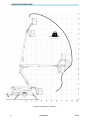
OPERATING ENVELOPE
]JJ
Unrestricted SWL
Height and Distance in Metres.
6
513868-000
TL49J
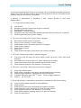
OPERATOR REQUIREMENTS
Please read this carefully, and ensure you have received the correct training prior to
operating this machine.
1.
$
hearing.
2.
You must have a good head for heights.
3.
Your primary concern must be the safe operation of the work platform, the safety of the
people working with you, and the safety of other persons in your working area.
4.
You must be familiar with the contents of this manual, and at no time attempt to operate
the machine beyond the recommended limits.
5.
The proper care of the work platform is a major factor in ensuring the safety of those who
work with it.
6.
You must not misuse the machine or ignore or interfere with the devices that have been
provided to maintain safety.
7.
Operation of the machine should be restricted to personnel who have been authorised to
operate the equipment and have received proper training.
TL49J
513868-000
7
WARNING NOTICES
1.
DO NOT operate this machine unless you have been fully trained in its safe use.
2.
DO NOT operate the machine on soft, slippery or sloping ground unless adequate
precautions have been taken.
$ ^J`2.
$
?]*^`*
Advice should be obtained from SNORKEL as to the type of supports and precautions
required before attempting to operate the machine outside these parameters.
3.
DO NOT use any equipment in the basket to increase the reach or working height of the
machine, e.g. ladders.
4.
DO NOT
_
e.g. notice boards.
5.
DO NOT use the machine for any application that may produce special loads or forces:
the manufacturer, SNORKEL Powered Access, must be consulted for approval of special
applications prior to use.
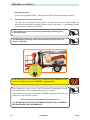
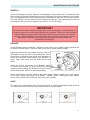
6.
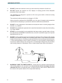
DO NOT use the machine close to live electrical conductors. The minimum safe working
distance for a machine working near overhead power cables is the maximum extended
?^
i.e. safe working distance for the TL49J is 24 metres. It is the operator‘s responsibility to
"
safe working distance is maintained. Erect a simple barrier tape at the safe distance.
?^
15m
15m
24m
26m
24m
7.
8
WORKING CLOSE TO POWER CABLES
safe working distance, the operator must ensure that the electricity supply has been
switched off. Before commencing work, a written permit to work must be obtained from
the owners of the power cables or the responsible authority.
513868-000
TL49J
WARNING NOTICES
8.
DO NOT operate the machine unless all four outriggers are down and in full contact
with the ground. The machine must be level and the wheels lifted visibly clear of the
surface before the booms are raised.
9.
DO NOT move the machine with the
basket raised and never allow cage
or booms to slew into the path of
oncoming vehicles.
10.
DO NOT
?]*^*
working near high buildings or structures, shielding and funnelling effects may cause high
wind forces on days when the nominal wind speed in the open is low. Wind speed can
either be measured from the work platform with a hand held anemometer or estimated
using the Beaufort Scale.
BEAUFORT WIND SPEED SCALE
The Beaufort Scale of wind force is accepted internationally and is used in communicating
* J " ?] ?J3@@*6
*
Approximate corrections for wind speeds at other heights are:
]@J
@]J
?J
?^?J
@J]^
Beaufort
Scale
M/Sec
@
@*^"^
4
"
5
["?J
Small trees in leaf begin to sway; crested wavelets on inland waterways
6
??"?@
?~"?
Whole trees in motion; inconvenience felt when walking against wind
8
?"]?
9
]]"]~
Slight structural damage occurs (chimney pots and slates removed)
TL49J
Ground Conditions
Raises dust and loose paper; small branches are moved
513868-000
9
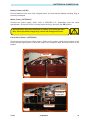
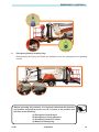
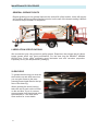
TOWING INSTRUCTIONS
behind a car or van at speeds of up 50mph (80km/h) where permitted.
1.
Before towing, check the capacity of the vehicle being used. (Machine weight will increase
6
2.
Ensure that the road tyres and brakes are in good, serviceable condition.
3.
loops and secured with the “R” clip on the end of the chain.
10
513868-000
TL49J
TOWING INSTRUCTIONS
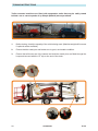
4.
Ensure that all outriggers are fully raised.
5.
Use the Jockey Wheel to raise or lower the tow bar coupling to position the machine
^J
*
6
8
7
11
9
6.
Apply the handbrake.
7.
Lower the tow bar coupling down onto the ball hitch using the Jockey Wheel
8.
#3
^J6*
9.
Fully raise the Jockey Wheel and lock in position.
10.
Release the Handbrake.
11. '
3
6
correctly.
TL49J
513868-000
11
HAND MANOEUVERING (Optional)
1.
Ensure that the booms are fully lowered, all outriggers are fully raised and the machine
is in a menoeverable condition.
2.
Engage the the friction drive cylinders against the trailer tyres by pulling actuating levers
forward and down until they lock overcentre.
3.
Ensure the power selector switch is set to Base.
4.
Disengage the handbrake, and ensure that the Jockey wheel directional locking pin is
removed
5.
Traction is controlled via the 2 hydraulic levers on the R/H side of the chassis.
6.
The left lever controls the left motor and the right lever the right.
Operating only the left lever forward will turn the machine right and the right lever will turn
the machine left, operate both levers together for parallel drive.
7.
When the machine is in position replace handbrake.
!
12
Ensure friction drive cylinders are disengaged prior to
platform operation or towing.
513868-000
TL49J
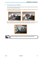
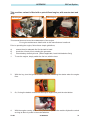
PRE-START CHECKS
The following Pre-Start Checks should be carried out before taking the machine to the
place of work.
1.
Damaged or Loose Fittings.
Visually Inspect the machine for signs of wear and tear, damage, loose or missing parts.
2.
Wheels. (For towing only)
>$|~[
3^*]^6*
The hydraulic oil tank is located underneath the slew cover on the right hand side of the
machine (looking from the cage end), Ref, Fig.2, section J With the booms and outriggers
in the transport position, the hydraulic oil level should be visible between the upper and
lower marks of the Sight Glass.
Top up with ISO Grade 22 hydraulic oil if necessary.
Serious injury or even death may result by not carrying out the
following checks of the interlock system before the platform is
used!
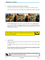
4.
Safety Switches.
Visually check the cage overload switch is free from damage.
Check all limit switch arms are free from damage and move easily (outrigger switches
shown in Fig.6 ).
With outriggers in transport position, it must not be possible to operate the extending
structure. With outriggers deployed, under load and top or bottom boom raised
^J
*
.
TL49J
513868-000
13
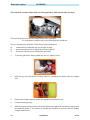
PRE-START CHECKS
5.
Emergency Stop Switches.
Emergency stop switches must operate correctly. Check that each stops the machine’s
controls and that restarting is prevented until all stop switches are unlatched.
6.
Emergency Lower/Slew.
^JJ
off, check:
The emergency lower switch located in the basket and ground control stations, lowers
the booms when operated.
The emergency slew, telescopic boom retraction can be operated by using the hand
pump and control lever at the ground control station.
To Reset the hydraulic system after checks;
!"
!#
$%
'"*"
*
!!#
All rams must be fully extended at the same time before returning them to their transit
If the Emergency Lower is used during normal operation, DO NOT use
the machine, Contact your local SNORKEL representative.
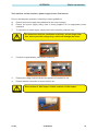
7.
Emergency Hand Pump.
With the unit set up for working (i.e. outriggers down, under load and the machine level
with wheels clear of ground) it is possible to lower the cage using the emergency hand
pump.
8.
Battery Power (Where applicable)
> 3 under the slew cover on both sides of the platform).
?]J"?@]J*
With machine level, the distilled water should cover the plates by approximately 6mm.
9.
Mains Power (Where applicable)
Check that the voltage and frequency of the power input matches that of the motor.
]*^
?J
voltage drop.
10.
Petrol/diesel Power (Where applicable)
>
*
14
513868-000
TL49J
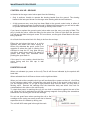
BATTERIES & POWER PACK
Battery Power, 24V DC.
Ensure batteries have been fully charged before use and that the Battery Isolating Plug is
securely connected.
Mains Power, (OPTIONAL)
>
??J ]]J]~J *>* *>
ON position.
All extensions must be a minimum of 2.5mm2, and no longer than
10m, due to possible voltage drop, which will damage the motor.
!
Petrol/diesel Power, (OPTIONAL)
Check the fuel and oil levels of the engine. Switch on the ignition using the key switch on the
slew mounted legend panel. Check the engine runs using the start and stop buttons in the
basket.
Batteries
fig 1.
Pump Handle
Oil Filler &
Sight glass
Power Pack
Hand Pump
fig 2.
TL49J
513868-000
15
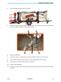
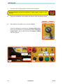
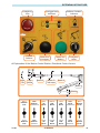
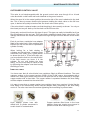
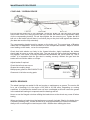
SETTING UP
1.
Park the unit in an appropriate location at the workplace.
Do not attempt to set up the machine on steep slopes, ramps or soft
ground.
2.
Apply the handbrake on the trailer and remove from the towing vehicle.
Platform
3.
Ground
With platform key switch set to ’Ground’ (Fig 3)
lower the outriggers by keeping the ‘Outrigger Motor Run’
button (Fig 4) pushed in, operate the appropriate ‘Outrigger
control lever’ (Fig 5), until all four are 25mm to 50mm
from the ground.
fig 3.
Fig. 4
Ground control
Levers.
Motor Run
(outrigger)
Motor Run
(Booms)
Emergency
Lower
Level
Indicator
fig 5.
16
Outrigger control
Levers.
fig 4.
513868-000
TL49J
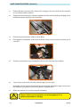
SETTING UP
4.
|%
3`@~6
ockey
wheel just clears the ground.
^*
|%?]
|Q
*3
shown below)
!
Take EXTREME care NOT to ground either the Basket, or the Jockey
Wheel during the next step.
*
Z_
%@~*
*
?]@~
%
Outriggers are fully deployed, and the wheels are well clear of the ground.
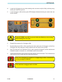
8.
Now, by using the Level indicator (Fig.5), raise opposite Outriggers until the bubble and
indicator ring are concentric (i.e., the bubble rests in the centre).
9.
Check that each LED on the Ground Control panel is still illuminated. This indicates that
*
The unit is designed to operate on a supporting surface of minimum
bearing strength of 50N/cm2.
The maximum outrigger load is 12.5kN.
TL49J
513868-000
17
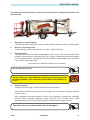
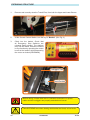
EXTENDING STRUCTURE
?*
Z
$
'
|*
2.
At the Ground Control Station, turn the key to ‘Basket’*3#*@6
@*
> * > all Emergency Stop Switches are
released (twist release). The platform
may now be raised, lowered or slewed
in any direction by operating the control
levers at the basket, whilst depressing
the motor run button (DEADMAN).
Outrigger Ram
Limit Switch
fig 6.
Before raising, ensure there are no overhead obstructions or power
!
18
*+-*/+0+"
513868-000
TL49J
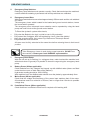
EXTENDING STRUCTURE
Emergency
Stop
Outrigger Load
Indicators
Platform Overload
Indicator
fig 4a.
Control
Selector
Motor Run
(Outrigger)
Motor Run
(Booms)
Emergency
Lower
4. Explanation of the Basket Control Station, Directional Control Levers.
Cage
Trim
Cage
Rotate
Boom 3
Boom 2
Telescope
Boom 2
Boom 1
Slewing
TL49J
Raise
Platform
Trim
Slew
Platform
Anticlockwise
Raise
Jib
Boom
Retract
TeleBoom
Raise
TeleBoom
Slew
Turret
Anticlockwise
Raise
Bottom
Boom
Lower
Platform
Trim
Slew
Platform
clockwise
Lower
Jib
Boom
Extend
TeleBoom
Lower
TeleBoom
Slew
Turret
clockwise
Lower
Bottom
Boom
513868-000
19
EXTENDING STRUCTURE
5.
A duplicate set of controls (excluding Slew Basket) is mounted on the Slew Turret under
the right hand side cover, which allows the platform to be operated from the Ground.
6.
At the Ground Control Station, turn the key to ‘Ground’*3#*@6
7.
Explanation of the Ground Control Station, Directional Control Levers
Cage
Rotate
Boom 3
Boom 2
Telescope
Boom 2
Boom 1
Slewing
20
Slew
Platform
Anticlockwise
Raise
Jib
Boom
Retract
TeleBoom
Raise
TeleBoom
Slew
Turret
Anticlockwise
Raise
Bottom
Boom
Slew
Platform
clockwise
Lower
Jib
Boom
Extend
TeleBoom
Lower
TeleBoom
Slew
Turret
clockwise
Lower
Bottom
Boom
513868-000
TL49J
SAFETY
EMERGENCY CONTROLS
1.
Emergency Stop
#
*
There are 2 Emergency Stop Buttons, one in the basket, and one on the ground control
panel.
The emergency stops are ‘Reset’ by twisting.
TL49J
513868-000
21
EMERGENCY CONTROLS
Emergency Lower.
In the event of a power failure, There are two ways of Safely lowering the basket.
2.
Emergency Lowering, method one
The operator or someone on the ground, can lower the booms to a safe position by
activating the Emergency lowering selector switch both ways, o n the Basket Control
Panel and the Ground Control Panel.
The Flick Boom cannot be lowered by activating the Emergency
Lowering Switch.
The Emergency lowering valve will automatically close when the
switch is released.
If the Emergency Lower is used due to a machine defect, DO NOT use the
machine, Contact your local SNORKEL representative.
If the Emergency Lower is used, The TOP and BOTTOM BOOMS must be
After Emergency lowering, any further POWERED lowering could cause an
12/#34
This could cause the Hydraulic operations to Fail.
ALL BOOMS MUST BE FULLY EXTENDED/RAISED, THEN LOWERED
BEFORE WORK CAN RECOMMENCE.
22
513868-000
TL49J
EMERGENCY CONTROLS
3.
Emergency Lowering a, method two.
You can operate the hand pump from the ground control station cage and operate the
boom controls and slewing functions.
To operate the hand pump, insert the lever over the pump shaft, then lower the lever to
a convenient position to start pumping.
Move a control lever to the required direction of movement, and operate the hand
pump. When the machine starts to lower, continue depressing the control lever.
Vigorous pumping is required to lower and slew the machine.
TL49J
513868-000
23
EMERGENCY CONTROLS
4.
Emergency Procedure, Manual Raising of Outriggers.
In the event of power failure, the outriggers can be raised to their transport position.
HP1, must be redirected from HP1, to port HP2,
and the blanking plug from HP2 must be replaced into HP1, using a 22mm spanner.
Once connected, move an Outrigger Control Lever in the required direction of
movement, and operate the hand pump. When the Outrigger starts to raise, continue
depressing the control lever.
Some hydraulic oil will be lost during this procedure. This will still
allow Emergency operations, but will need to be replaced before full
normal use can resumed.
5.
!
Cage Overload
In the event of the cage being overloaded, an audible alarm will sound and the cage
controls will cut out.
To re-start, enough load must be removed from the cage so that the alarm stops
sounding.
In cases where the overload can not be immediatley removed or the cage has fouled,
then the overload override selector switch can be used to move the platform to a safe
position so that the overload can safely removed.
The Key, Motor Run/Deadman and a Control Lever must be operated
at the same time to effect this action
24
513868-000
TL49J
EMERGENCY CONTROLS
6.
Emergency Battery Isolating Plug.
Disconnecting this plug will isolate the batteries from the powerpack and operating
circuits.
Before operating this machine, it is important that both the Operator
and another responsible person on site, is aware of the position and
function of the following:
A) Emergency Stop Buttons.
B) Emergency Lowering Buttons.
C) Emergency Slew Drive Shaft.
D) Battery Isolating Plug.
TL49J
513868-000
25
STOWING THE MACHINE
1.
Fully lower all the booms.
2.
Engage the Transit Pins, and lock in place using ‘R’ clip.
3.
With platform keyswitch set to ‘Ground’:
Raise the outriggers by simultaneously depressing the ‘MOTOR RUN Outrigger’ button
and using the appropriate control levers, two at a time, alternating between the cage and
tow bar end until the road wheels are in contact with the ground.
Only when the road wheels are in contact with the ground should the unit be lowered
further until the jockey wheel makes contact with the supporting surface.
Now fully raise the outriggers until they are in the stowed position.
Switch off the platform and ensure all loose items/covers are secure before towing the
unit.
The machine is now ready for transportation.
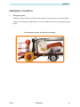
TRANSPORT PIN LOCATIONS – SHOWN READY FOR TRANSPORT
Lower Boom
26
Upper Boom
513868-000
TL49J
MAINTENANCE
The unit must have a thorough inspection carried out every 6 months
""#$
%
Thorough Inspection produced by a competent person.
Always ensure the machine structure is in good, sound, undamaged
condition. Any inspection procedure is always aided by keeping
the machine clean. NB. Do not steam clean the battery charger or
electrical components.
!
Daily Checks.
1.
Damaged or Loose Fittings.
Visually Inspect the machine for signs of wear and tear, damage, loose or missing
parts.
2.
Wheels.
>$|~[
3^*]^6*
The hydraulic oil tank is located underneath the slew cover on the left hand side of
the machine (looking from the cage end), Ref, Fig.2, section J. With the booms and
outriggers in the transport position, the hydraulic oil level should be visible between the
upper and lower marks of the dipstick.
Top up with ISO Grade 22 hydraulic oil if necessary.
4.
Safety Switches.
Check all limit switch arms are free from damage and move easily outrigger switches.
With outriggers in transport position, it must not be possible to operate the extending
structure.
With outriggers deployed, under load and top or bottom boom raised approximately
^JNOT be possible to operate the outrigger controls.
&
5.
Emergency Stop Switches.
Emergency stop switches must operate correctly. Check that each stops the machine’s
controls and that restarting is prevented until all stop switches are unlatched.
TL49J
513868-000
27
MAINTENANCE
The unit must have a thorough inspection carried out every 6 months
""# $
%
Thorough Inspection produced by a competent person.
!
Always ensure the machine structure is in good, sound, undamaged
condition. Any inspection procedure is always aided by keeping the
machine clean. NB. Do not steam clean the battery charger or electrical
components.
Weekly Checks.
1.
Apply grease to the slew gear wheel and all grease nipples.
2.
From the Ground controls, Fully extend the Telescipic Boom and visually inspect along
its entire length for signs of wear and tear damage or deformation.
3.
Check battery acid level, top up with distilled water if required (maximum 6mm over
plates when battery is standing level), and check mains cable wiring.
Monthly Checks.
1.
Thorough inspection to be carried out by a competent person.(LOLER)
FOR ENGINE MAINTENANCE REFER TO MANUFACTURES GUIDELINES
28
513868-000
TL49J
MAINTENANCE
Slew Drive Gears.
The slew drive gear is designed to be largely maintenance free. However, we recommend the
gear teeth be greased on a monthly basis with a high pressure grease. Additionally, the ring
gear and gear box should be greased on a six monthly basis. The grease nipple for the ring
*
lifting one of the side covers, and slewing the structure appropriately.
Grease Nipple
The ring gear should be inspected on a six monthly basis for excessive play. It is unlikely there
will be any wear if the machine is maintained correctly.
Grease Nipples
$J{
*
boom to approximately half way. Then gently elevate the top boom, whilst observing the ring
*
J*^
inner and outer bearing rings.
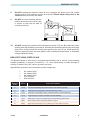
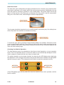
Checking Limit Switch Operation.
The limit switches require no maintenance, other than a visual inspection, on a pre operation
basis. This is an important check, to ensure the switch is not mechanically damaged, and the
roller is always in contact with the cam, when not under load.
The switch operation can be simply checked, by observing the LED display when deploying
the stabilizers. As an outrigger foot touches the ground and becomes loaded, the appropriate
light will change to green. This indicates that the switch contact has operated correctly.
Outriggers NOT
under load
Outriggers
under load
If the LED displays green at any other time then the machine must not be operated, until the
*
TL49J
513868-000
29
MAINTENANCE
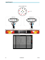
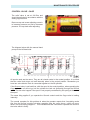
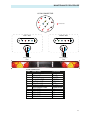
13 PIN CONNECTOR
8
9
7
1
10
2
4
3
11
12
LEFT H/S
= Not Used.
5
13
RIGHT H/S
+
-
-
2 Core Cable
2 Core Cable
+
6
RH Registration
Lamp
LH Registration
Lamp
13 PIN CONNECTOR
PIN
1
2
3
4
5
6
7
8
9
10
11
12
13
30
FUNCTION
LH INDICATOR
FOG LAMP
NEGITIVE
RH INDICATOR
RH TAIL LAMP
BRAKE LAMP
LH TAIL LAMP
REVERSING LAMP
NOT USED
NOT USED
NOT USED
NOT USED
NOT USED
513868-000
COLOUR
YELLOW
BLUE
WHITE
GREEN
BROWN
RED
BLACK
DARK BLUE
N/A
N/A
N/A
N/A
N/A
TL49J
APPENDIX
Bi-Fuel Option
"#
stop
Diesel Engine
Petrol Engine
This manual does not cover the maintenance of the engine.
!
Prior to operating the engine, follow these simple guidelines;
a)
b)
c)
ensure there is adequate fuel for the task in hand
check the oil level prior to starting the generator
Check battery electrolyte level. (Where applicable, Lead Acid batteries Only)
?*
$
*
2.
With the key, turn the ignition to start, motor on, releasing the starter when the engine
*
@*
%
*
4.
With the engine running, It will now be possible to operate the machine Hydraulic controls
as long as there is power in the main batteries.
TL49J
513868-000
31
Generator option
APPENDIX
$$
'
"#
This manual does not cover the maintenance of the generator.
!
Prior to operating the generator, follow these simple guidelines;
a)
b)
c)
ensure there is adequate fuel for the task in hand
warm the engine prior to switching off at the platform.
check the oil level prior to starting the generator
?*
$
*
2.
With the key, turn the ignition to start, motor on, releasing the starter when the engine
*
@*
*
~*
>
=
*
5.
With the engine running, power will automatically be supplied to the battery charger, and
the platform socket. It is possible to operate the machine lift controls with the battery
charger switched on.
32
513868-000
TL49J
APPENDIX
Mains connection
*
+
Prior to operating the generator, follow these simple guidelines;
a)
b)
Ensure the power supply being attached is the correct voltage.
Ensure the power supply being used is being supplied via an appropriate power
extension.
?*
$
*
!
All extensions must be a minimum of 2.5mm2, and no longer than
10m, due to possible voltage drop, which will damage the motor.
2.
Connect an appropriately rated power extension.
@*
*
4.
Ensure that the connection is secure before use.
!
TL49J
Blue sockets is 240V output. Yellow sockets is 110V output.
513868-000
33
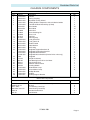
SERVICE MANUAL
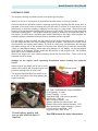
Introduction
The Snorkel TL49J, is a versatile means of gaining access in difficult locations.
The access platform is extremely safe in operation providing that basic rules are observed in
setting up the machine. This manual focuses on the Maintenance and repair of the machine.
Please read the Operators Manual available from Snorkel or from your local distributor prior
to operating the machine
All operators and service personnel should have read and understood the Operators manual,
and received full training in the safe use of the machine before attempting to use it or
carrying out repairs.
Always quote your machine serial number and date of manufacturer when ordering spare
parts.
Part number for this manual can be found on the inside front cover.
CONSTRUCTION STANDARDS
The machine complies fully with the requirements of
European Standard EN280 : 2001.
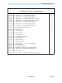
Contents
Technical Characteristics
2
Fault Finding
5
Fault Finding Matrix
7
Notes
14
Maintenance Schedule
15
Maintenance Procedure
17
1
TECHNICAL CHARACTERISTICS
Trailer / Superstructure / Outriggers.
This consists of a variety of welded and folded fabrications, which, where necessary,
contain bushed stainless steel pivots with grease nipples. The main components are shot
blasted and them powder coated, and the cylinders are wet painted. The machine also
includes fully automatic running gear with auto reverse and also integrated trailer lighting.
At the towing end of the machine there is a heavy duty coupling head as well as a
pneumatic jockey wheel. The maximum allowable load on the outriggers is 10.3kN and
the allowable sideway inclination is 5 degrees.
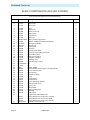
Equipment
Bottom Ram
Top Ram
Dropnose Ram
Stabiliser Ram
Basket Levelling Ram
Bottom & Top Ram Lock Valves
Control Valve (Cage)
Control Valve (Ground)
Control Valve (Stabiliser)
Bushes
Pivot Pins
Tyres
2
Double acting: Bore Ø 60.0 mm
Rod Ø 40.0 mm
Double acting: Bore Ø 60.0 mm
Rod Ø 40.0 mm
Double acting: Bore Ø 60.0 mm
Rod Ø 40.0 mm
Double acting: Bore Ø 70.0 mm
Rod Ø 40.0 mm
Double acting: Bore Ø 40.0 mm
Rod Ø 20.0 mm
Pilot operated over centre valves
Monoblock unit consisting of five
double acting spools
Monoblock unit consisting of four
double acting spools
Monoblock unit consisting of four
double acting spools
Acetol resin polymer with sintered
bronze base (DX)
Stainless Steel Bright Bar
To Grade BS970 303 S31 CW
215R16C 8 Ply
TECHNICAL CHARACTERISTICS
Power Pack (Battery Power or Mains Power).
Fully integrated power pack consisting of Motor, Pump, Relief valve, non return Check,
Return filter with dip stick for checking oil level. Pump is fitted with internal suction
strainer. Return filter is fitted with a breather and is used for topping up if oil is required.
The tank is fitted with a drain plug on the bottom face. A quick release coupling for
checking oil pressure is fitted on top of the pressure port.
Power Pack (I.C. Engine).
Engine is fitted with a separate pump, which is fitted with a return filter and dip stick.
Return filter is fitted with a breather and is used for topping up if oil is required. The tank is
fitted with a drain plug on the bottom face. The relief valve is mounted independently in
close proximity to the pump together with a quick release coupling for checking hydraulic
pressure
The engine is fitted with electric start with its own independent start battery. The engine
can be started from the engine’s start / stop key switch and from the remote start / stop
push button fitted in the cage.
Safety Systems.
Full fail-safe hydraulic and electrics as required by EN280 and the Machinery Directive.
Outriggers are pressure sensitive to prevent operating the booms until the outriggers are
in full contact with the ground. Outrigger condition is monitored constantly and full visual
indication is given by 4 independent LED’s mounted on the Ground control panel.
It is not possible to raise the outriggers when the booms are extended. In case of power
failure all booms can be lowered and the slew operated using a manual hand pump fitted
in the cage. From the ground the top and bottom booms can be lowered manually by
actuating the manual override valves fitted to the Bottom and Top cylinders. The slew can
be operated by manually turning the slew motor shaft.
The machine carries full CE approval.
3
TECHNICAL CHARACTERISTICS
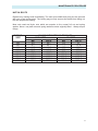
Operating Speeds and Noise Level.
Due to oil viscosity and the fluctuating supply of power on a machine fitted with Batteries
and / or a I.C. engine as its power source the following nominal operating speeds are
indicated. All speeds have been taken with fully charged batteries and at ambient
temperature of +10deg. Significant speed differences will be experienced if operating in
cold climates and with batteries in a semi discharged state or if the I.C. engine is poorly
maintained. All speeds have been taken from the cage with a SWL of 100Kg. Mains
power powered machines have different speeds
Drop Nose up
: 18sec
Drop nose down
: 11sec
+/- 1sec
Bottom Boom down
Top Boom down
: 22sec
: 16sec
+/- 5sec
+/- 5sec
Slew CW 180deg 39 sec (back) Slew CCW 180deg
: 39sec
+/- 10sec
Bottom Boom up : 40sec
Top Boom up
: 24sec
Basket rotation, from Lock to Lock (90deg) = 6sec
Noise Level:
+/- 2sec
70 db(A) Battery
70 db(A) Mains power
105 db(A) I.C. Engine
Duty Cycles.
The mains power pack and the I.C. Engine are both continuously rated. The I.C. Engine
speed is fixed and must not be altered.
Battery.
Well maintained batteries will get the following operations from one full charge :
10 lift and lowers with a 5 min brake (to simulate working) at full elevation and when back
at ground level + 1 Outrigger raise and lower…...repeated 4 times.
Under normal circumstances this will give the operator a full days work. Connecting the
charger to the mains supply, will boost the batteries and give an even longer duty cycle.
The machine cannot be directly from the charger, as the current draw from the motor is
higher than the output from the charger.
NOTE: The 5 min cooling of the motor is important to prevent motor overload.
4
FAULT FINDING
It is recommended that fault finding is only carried out by technically competent personnel.
Whilst every effort has been made to ensure these procedures are as comprehensive as
possible, they will not cover all eventualities.
If difficulty is experienced in identifying a fault, contact Snorkel or their local
representative.
1. I.C. Engine will not start (if fitted):
A)
B)
C)
D)
E)
F)
Fuel in tank?
Emergency stops are reset (cage & ground controls).
Engine Ignition switched on
Start Battery correctly charged
If engine is cold, has choke been applied (manual) Does the choke pull in (electric).
Check engine blade fuse (next to engine)
2. DC motor not turning when trying to lower outriggers:
A)
B)
C)
D)
E)
F)
G)
Key selector switch must be on ground.
Can you hear contactor on motor clicking ?
Check battery level / Should be minimum 2/3 charged
Check motor contactor.
Check motor brushes.
Motor fuse
Check that the emergency stop button has not been activated.
3. DC motor turning but not able to operate outriggers:
A)
B)
C)
D)
Top boom must be down and boom switch (under top boom, above slew post)
activated
Limit-switch arm must be secure on switch spindle (boom switch)
Check that diverter valve is de-activated (see hydraulic circuit)
Check hydraulic pressure / No pressure - Check pump.
4. DC motor not turning - After having lowered all outriggers
A)
B)
C)
D)
E)
Check key selector switch
Check that no emergency stop button has accidentally been activated.
Check outrigger switches - Outriggers must be correctly set.
Is audible warning in cage “ON” ? - If yes - Check outrigger switches.
Check 2 - . B), C), D), E).
5. Boom will not raise / lower when control lever is operated and DC motor running
A)
B)
C)
D)
E)
F)
G)
Correct control station selected, ie ground/platform.
Check oil level.
Check that diverter valve is activated (see hydraulic diagram)
Check that other control valve has all spools in centre position
Check hydraulic pressure / No pressure - Check pump
Check that emergency lowering valve is not open (on cylinder)
Check for obstructions.
5
FAULT FINDING
6. Audible alarm activated - No boom movements
A)
You have a light leg. Check level and Limit switch on outriggers
7. Slew will not operate in either direction with DC motor turning
A)
B)
C)
D)
Check that appropriate control station has been selected,
Check that machine is on level ground. Slew will not operate if machine is out of
level.
Check for obstructions
Check that you have not reach the slew stop. 2002 machine specifications will only
slew +/-355 deg from the stowed position. Earlier machine would slew +/- 450 deg
from the stowed position.
8. Loss of movement on Mains powered machines or I.C. engine powered machines
A)
B)
C)
Check dump valve. To enable movement the dump valve must pull in to stop oil
going to tank
Check oil pressure.
Check pump and coupling
9. If Mains motor / I.C. engine stalls when trying to operate machine
A)
Check relief valve setting
10.
If Mains motor stalls when operating machine
A)
B)
C)
Check for voltage drop.
Use shorter extension lead
DO NOT RUN MACHINE - Motor will fail if voltage reading on motor terminals are
below 10% of motor rating when motor is running under load.
11. RCD on mains powered machines keeps tripping
A)
B)
Check for water ingress in terminal boxes.
Check motor Start & Run capacitors.
12.
0.5A fuse on control circuit keeps popping (Mains Powered Machines) .
A)
Check coil on selector valve and dump valve for cracks/signs of water damage.
13. Burnt out mains isolating transformer (Mains Powered Machines)
A)
B)
6
Check fuse.
Check coil on selector valve and dump valve for cracks/signs of water damage.
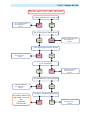
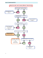
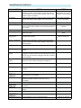
FAULT FINDING MATRIX
Motor will not start (Petrol)
Is the Ignition Switch, turned on?
Turn ignition to ON
& Read Operators
Manual
NO
YES
Are all Emergency Stops Reset?
YES
NO
Reset Emergency stops
& Read Operators
Manual
Does the Engine have Oil & Fuel?
Fill up the Oil or Fuel tank
& Read Operators
Manual
NO
YES
Is the Choke On?
YES
NO
Apply the Choke
& Read Operators
Manual
Are the Batteries Fully Charged?
Charge Batteries
& Read Operators
Manual
If further advice is
required, consult
an
Snorkel
Technician.
NO
YES
Has the Circuit Breaker tripped?
NO
YES
Reset the Circuit Breaker
& Read Operators
Manual
7
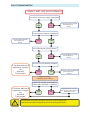
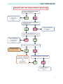
FAULT FINDING MATRIX
Motor will not start (Mains)
Is the Correct Power supply Connected?
YES
NO
Connect power supply
& Read Operators
Manual
Is the Selector Switch, turned on?
Select switch position
& Read Operators
Manual
NO
YES
Are all Emergency Stops Reset?
YES
If further advice is
required, consult
an
Snorkel
Technician.
NO
Reset Emergency stops
& Read Operators
Manual
Has the Circuit Breaker tripped?
NO
YES
Reset the Circuit Breaker
& Read Operators
Manual
Motor stalling.
Working Hard, Noisy
Check the voltage at the motor is
230V when the motor is turning?
If further advice is
required, consult
an
Snorkel
Technician.
!
8
YES
NO
Voltage Drop may be
the cause, Use a shorter
Extension lead
All extensions must be a minimum of 2.5mm², and no longer than
10m, due to possible voltage drop, which will damage the motor.
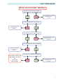
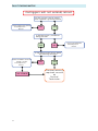
FAULT FINDING MATRIX
Motor will not start (Battery)
Has the correct control switch
been selected? (ground/ basket)
YES
NO
Select appropriate control
& Read Operators
Manual
Are the Batteries connected?
Connect Batteries
& Read Operators
Manual
NO
YES
Are all Emergency Stops Reset?
YES
NO
Reset Emergency stops
& Read Operators
Manual
Are the Batteries Fully Charged?
Charge Batteries
& Read Operators
Manual
If further advice is
required, consult
an
Snorkel
Technician.
NO
YES
Has the Circuit Breaker tripped?
NO
YES
Reset the Circuit Breaker
& Read Operators
Manual
9
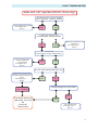
FAULT FINDING MATRIX
Booms will not raise (Motor Running)
Has the correct control switch
been selected? (ground/ basket)
Select appropriate control
& Read Operators
Manual
NO
YES
Is the Motor Run / Deadman
being pressed?
YES
Press the Deadman
& Read Operators
Manual
NO
Are all the
Outriggers under load? (LEDs)
Reset the Outriggers
until all LEDs are
Illuminated
& Read Operators
Manual
NO
YES
Are the Hydraulics under pressure?
A change of motor
tone can be heard.
YES
If further advice is
required, consult
an
Snorkel
Technician.
NO
Is there enough Oil in the tank?
YES
NO
Top up Oil Level
& Read Operators
Manual
10
FAULT FINDING MATRIX
Booms will not lower (Motor Running)
Is there an obstruction below,
the basket or booms?
Remove obstruction, or
reposition
& Read Operators
Manual
YES
NO
Is the Motor Run / Deadman
being pressed?
YES
Press the Deadman
& Read Operators
Manual
NO
Are all the
Outriggers under load? (LEDs)
Reset the Outriggers
until all LEDs are
Illuminated
& Read Operators
Manual
NO
YES
Are the Hydraulics under pressure?
A change of motor
tone can be heard.
YES
If further advice is
required, consult
an
Snorkel
Technician.
NO
Is there enough Oil in the tank?
YES
NO
Top up Oil Level
& Read Operators
Manual
11
FAULT FINDING MATRIX
Outriggers will not extend/retract
Has the correct control switch
been selected? (ground/ basket)
Select appropriate control
& Read Operators
Manual
NO
YES
Is the Motor Run / Deadman
being pressed?
YES
NO
Is the Boom Down Switch Made
and working correctly?
Lower the booms until the
switch is made
& Read Operators
Manual
NO CHANGE
12
NO
YES
If further advice is
required, consult
an
Snorkel
Technician.
Press the Deadman
& Read Operators
Manual
FAULT FINDING MATRIX
Slew will not operate (Motor Running)
Has the correct control switch
been selected? (ground/ basket)
Select appropriate control
& Read Operators
Manual
NO
YES
Is there an obstruction
Preventing the slewing action?
NO
Remove obstruction, or
reposition
& Read Operators
Manual
YES
Are all the
Outriggers under load? (LEDs)
Reset the Outriggers
until all LEDs are
Illuminated
& Read Operators
Manual
NO
YES
Has the slew reached the slew stop?
Reverse the control lever
until the slewing action returns.
& Read Operators
Manual
NO CHANGE
YES
NO
Is there enough Oil in the tank?
NO
If further advice is
required, consult
an
Snorkel
Technician.
YES
Top up Oil Level
& Read Operators
Manual
13
NOTES:
14
MAINTENANCE SCHEDULE
Maintenance.
General - A well maintained machine will give years of trouble free operation. The machine
requires very little maintenance. The biggest problem is operators not looking after the
machine and physically damaging the structure or its individual components during use or
when being towed on the road.
Note - All machines being operated in the UK must have a thorough inspection carried out
every 6 months in accordance with LOLER Regulations 1998 and a Certificate of Thorough
Inspection produced by a competent person. Contact Snorkel for further details.
Operators Responsibility - It is the operator’s responsibility to ensure that the machine is safe
to use. To do so, he must carry out all the Daily checks prior to using the machine. From a
pure maintenance point of view only the Weekly & 6 monthly maintenance requirement is
required. Obviously when the engineer is working on the machine he now becomes the
operator and must carry out the Daily checks.
Maintenance Schedule—What is shown here is very much worst case scenario covering
most eventualities. If further advice is needed contact Snorkel or its local representative.
The reference number shown on the far left hand side of the table refers to the relevant
Maintenance Procedure Sheet in this manual. If this manual was not issued with the
machine, check for updates and revisions from Snorkel or its local representative.
- IMPORTANT Always ensure the machine is in good, sound, undamaged condition.
When carrying out maintenance and repairs always clean the machine
thoroughly. Take care not to steam clean the batteries or the electrical
components.
Failure to maintain the machine as specified will invalidate your warranty.
15
MAINTENANCE SCHEDULE
DAILY CHECKS
ACTION
NOTES
Hydraulic System
Top up with machine standing on level ground in the
travelling position. Fill oil using the return line filter on
top of the tank. Oil must be at the bottom mark on the
dipstick. Look for oil leaks.
Use SHF22 oil or
equivalent. Change oil
and filter every 6 months
I.C. Engine
Check oil, filter and fuel. Check for leaks. Check battery.
Top up with distilled water only 6 mm above plates.
See OEM manual for
more information
Level Gauge
Physical damage
Check that level gauge is present and secure
Check for physical damage to the booms, tie bars,
basket, slew and the chassis. Check all warning labels
are in place
Do not use damaged
machine
Nuts, Bolts, Fittings
Check for missing and loose nut and bolts.
Replace immediately
Locking pegs
Check that all locking pegs are present. Check that no
shafts are seized.
Broken peg = seized
shaft
Transport locks &
Lifting points
Check that all transport lock pins are present. Check for Do not transport machine
damaged lifting points
without locking pin.
Battery & Charging
If fitted. Check operation of charger. Record specific
gravity of each cell. Clean top of battery. Clean and
check terminal
Emergency stop
Check that all emergency stop switches are working
Electrical system
Check for correct operation of the complete electrical
system
Electrical Safety
system
Check that you can not operate the booms until
outriggers are down and in contact with ground. Check
that you can not raise the outriggers with top or bottom
boom elevated.
Hydraulic Safety
system
Check that all emergency lowering valves work. Check
emergency slew. Check emergency handpump
Wheels
Check tyres for damage. Wheel nuts and tyre pressure
Running gear
Check parking brake. Check overrun device. Check for
damage
Trailer lights
Check for correct operation if towing
WEEKLY
CHECKS
Depending on use and operating condition different
intervals may be acceptable
Lubrication
All grease nipples. Depending on machine use and
operating condition different intervals may be
acceptable.
Slew Gear
Check slew gear for excessive wear. Grease
MONTHLY
CHECKS
Can be done 6 monthly depending on operating
conditions
DC motor
Check and replace motor brushes if machine is used
heavily
Wheel bearings
Check for wear - Do checks at every 3000 miles
Turn to release
55PSI 3.8 Bar
2/3 worn = Replace
6 MONTHLY
CHECKS
Thorough Inspection Contact Snorkel or its local representative.
16
Change oil and filter
MAINTENANCE PROCEDURE
Power Pack.
The hydraulic system is fully self contained. Oil tank capacity is 15 Litres. When operating
above 0 degrees C we recommend using ISO22 Grade Hydraulic Mineral Oil (See Health &
Safety guidelines supplied with the oil prior to handling).
Replace oil and filter every 6 months. The biggest cause of hydraulic problem, sticking
valves, leaking cylinders etc.. are due to contaminated oil. There is no need to replace the oil
in the hoses. Just replace the oil in the tank.
No oil is used by the system so if oil is required this would indicate an oil leak which must be
investigated prior to using the machine.
Correct Oil Level.
It is critical that the correct oil level is maintained. Too little oil will cause cavitation and failure
of the pump. Too much oil will lead to oil leak through the return filter breather or a massive
oil leak when using the emergency lower valves on the top and bottom boom. The rams are
double acting. When using the emergency lower valves you require free space in the tank to
accommodate oil which normally would be pumped into the annular side of the cylinder. If
this should happen, just clean up the oil spillage. Fully extend ALL rams. Then close up all
rams and check the free space in the tank using the dip stick. Oil must be at the bottom mark
on the dipstick to ensure correct level.
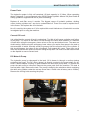
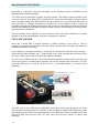
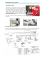
DC Motor & Pump.
The hydraulic pump is submerged in the tank. Oil is drawn in through a suction strainer
protecting the pump. The DC motor (shown) is directly coupled to the pump shaft. On AC
motor a small adapter coupling is used between the motor and pump shaft. To replace the
pump the tank must be removed. Remove the power pack from the machine. The tank is
secured with 4 bolt. Remove the tank. The pump is bolted to the aluminium block containing
the relief valve (Hidden under the red cap shown here - Relief valve is factory set to 210Bar).
Remove the 4 fixing bolts securing the pump.
17
MAINTENANCE PROCEDURE
When the pump has been removed it can be split and the gears can be inspected for wear. If
the gears are worn (or broken) we recommend replacing the complete pump. The
replacement pump is complete with gears, front and back plate all ready to bolt on in place of
the old unit (strainer is not included). Before fitting the pump, apply a liberal amount of clean
hydraulic oil to the gears. Take great care to torque the 4 - 5/16 Hex fixing bolts evenly to 13
ft/lbs to ensure correct operation of the pump. DO NOT OVERTIGHTEN. Before fitting the
tank. Thoroughly clean the tank and the magnet you will find inside the tank. De-grease,
replace the large “O” ring and apply a small amount of silicone around the circumference of
the de-greased tank neck. Push the tank back on and secure with the 4 bolts removed
earlier.
DC Motor.
DC motor - The DC motor can be removed without worrying about oil spillage. Remove the 2
long bolts at the end of the motor. You can now withdraw the motor. Take care not to strain
the wires.
To ensure optimum performance from the DC motor we recommend replacing the motor
brushes when they are 2/3 worn. If the machine is used extensively (quite normal in a hire
environment) this can be required at least every 6 months. To replace the brushes, fully
remove the motor from the power pack. Blow out all the brush dust using compressed air
before reassembling the motor.
Check the motor shaft bearing and replace if worn. We also recommend replacing the
contactor at the same time as replacing the brushes. The unit is fully sealed (to prevent
sparks igniting battery gases) and contain no serviceable parts.
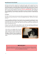
If the motor is not stopping when the green
motor run button is released, and no power is
at the contactor coil, replace contactor immediately. To stop the motor in this case. Use
the battery disconnect plug or lightly tap the
contactor on its end (1) with the handle of a
large screw driver to free the internal contact
points
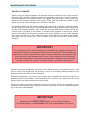
IMPORTANT
The main relief valve is factory set at 210 bar and should normally not need
adjusting. Breaking the seal (3) during the warranty period, for whatever reason, will invalidate the warranty.
18
MAINTENANCE PROCEDURE
Power Pack
Fully integrated pump, tank, preset relief valve and return filter. The biggest cause of
hydraulic problems is down to contaminated oil. Change oil and filter at least every 6
months, even though the hydraulic system is a closed system. The only access for
external dirt is through the filter breather. You will have contamination due to seal kit wear
(black sludge in the bottom of the tank, mechanical wear from the gear pump, valve block
and cartridges in addition to water contamination due to tank condensation. See power
pack section for more details.
SOL1
This valve diverts oil from the outrigger control valve first to the ground control valve and
then to the basket control valve. Never operate the coil unless it is on the valve cartridge.
You risk burning out the coil.
Ground Control Valve
This gives you full control over all functions apart from the basket slew. The adjustable
relief valve is set at the factory to approximately 190 bar. It should be set so that when you
lift the bottom boom from rest you can just lift the full safe working load (SWL). The centre
position is closed to prevent oil back feeding and running back to tank when operating the
basket controls.
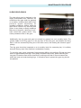
Slew Motor
The slew motor is bolted directly on the slew gear. Apart from greasing and checking for
oil leaks it requires no maintenance.
Platform Controls
Is identical to the ground control apart from the extra valve bank needed to control the
slewing basket ram. The orifice in the Basket slew fitting is there to prevent the basket
turning too quickly.
Hand Pump
Enables you to lower and operate the slew in case of emergency. The pump is fed from
the general return line. It is theoretically possible to extend the cylinder with the hand
pump but the force required is excessive and the fixing bracket for the hand pump is not
designed to take such a load. If no resistance is felt when operating the hand pump try to
operate the basket slew or the drop nose to prime the pump.
Basket Slew
Cylinder has no lock valve. It relies on the closed centre of the spool to prevent it moving.
All Other Boom Cylinders
Have lock valves fitted to prevent uncontrolled movement in case of hose failure.
Stabiliser Control Valve
In the centre position, this block has the B port connected to the tank. This is to ensure
that the outrigger cylinder check valve closes quickly when setting up the machine. The 4
restrictors shown are there to prevent cylinder juddering caused by the check valves fitted
to the outrigger cylinders.
19
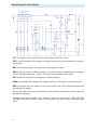
MAINTENANCE PROCEDURE
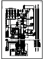
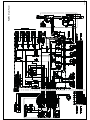
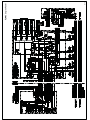
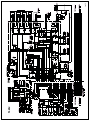
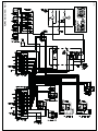
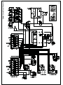
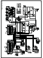
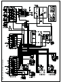
Read this in conjunction with the description of the hydraulic circuit (31HC20A) for the
Battery 24VDC powered machine.
The TL49J can be fitted with a variety of power options. The battery powered machine has
only one solenoid valve fitted (SOL1). Both the I.C. engine and the mains powered version
have a separate dump valve fitted (SOL2). This is because oil is in circulation all the time, not
only just when a cylinder movement is required as on the battery version. Having oil
circulating through the different valve blocks may lead to uncontrolled movements should the
controls accidentally be operated. By fitting a dump valve the oil will always go to tank unless
the dump valve is activated.
See the relevant circuit diagram for your machine at the end of this handbook or contact
UpRight or its local representative for further information if required
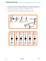
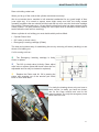
TOP & BOTTOM RAM
Each ram is fitted with a manual release to enable lowering of the boom in case of
emergency. Depress the red button and hold. When released, the red button will spring out
and the movement should stop.
If the cylinder is operating erratically - Jamming at odd intervals with the motor running. Check that the little restrictor disc (1) fitted at the nose of the cartridge has not come loose.
The disc is held in pace with a small circlip. Replace cartridge.
The O/C valve enables the oil to flow freely into the cylinder but will not let any oil flow out
until a pilot signal is received when pumping oil into the annular side of the ram. The O/C
valve will then open up and let oil flow out, in a controlled manner, to prevent boom
juddering.
Em. Lower Part no : 13-2228
(1)
Type CBBA part no : 13-0392
The O/C valve is also fitted with an adjustable relief valve which must be set to 1.25 times
the maximum pressure inside the cylinder. If the cartridge is marked with CBBA you screw
the adjusting screw CCW to increase pressure. If screwed fully CW the cartridge is now fully
open and does not hold any load. The O/C valve must be set correctly to ensure safe
operation.
20
MAINTENANCE PROCEDURE
Ram not holding under load.
When you let go of the controls the cylinder movement must stop.
We do not advise that a machine is left extended unattended for any great length of time
(over night etc.) It is normal to expect some slight creep over time, but during normal
operating conditions the ram should hold the load and not move once the lock valve cartridge
has closed. (This may take up to 1-2 sec after the directional valve has been returned to the
centre position. The pilot pressure holding the valve open must be allowed to drain back to
tank to allow the lock valve to seat fully).
When a cylinder is not holding you must decide which part has failed.
x Cylinder Piston Seal
x O/C valve (or check valve)
x Emergency Lowering cartridge (if fitted)
The best and quickest way of establishing this are by removing all hoses (carefully) to see
where oil is leaking out.
If oil is coming out from :
x
The Emergency lowering cartridge is faulty.
Clean or replace
x
The O/C (or check valve) is faulty. Clean, adjust
relief valve or replace (Note that check valves are non
adjustable and can only be cleaned or replaced)
x
Replace the Piston seal kit. Oil is passing the
piston and escaping out of the annular port which
have no lock valve fitted
For clarity the drawing shows only one hose to
each service. In reality you have two hoses,
one for the Cage controls and one for the
ground controls. It is only the emergency lower
which has one hose.
21
MAINTENANCE PROCEDURE
DROPNOSE RAM
Is fitted with two O/C valves. You have two
things you can try to help you to decide which
component has failed :
First remove all hoses (take care) so you can
see where oil is escaping
x If the oil is escaping from the full bore side
the full bore O/C valve is the problem.
x Slowly open the adjusting screw for the O/C
relief valve on the annular side. The piston
seals have failed if oil starts to come out
from the annular side and the cylinder is
starting to close up at an increased speed,
replace the piston seals
Dropnose cylinder with welded on block
containing two adjustable O/C valves
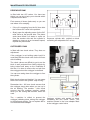
OUTRIGGER RAM
Is fitted with two check valves. They have no
adjustment.
If the outrigger is not holding under load it is
most likely that the check valve for the full bore
side is leaking.
The check valves are difficult to get to as the
block is well protected from falling objects by
being tucked well away on the underside of
the ram. You have to remove the rod pin from
the outrigger when the outrigger is retracted.
You can now swing down the outrigger to free
the cylinder.
Both check valves are identical. You can swap
them over to see if the cylinder stop moving.
Remember the x full bore check ensures that
the outrigger stays down when you are up in
the air working. The annular x side check
ensures that the outrigger remains vertical
when you are towing the machine down the
road.
The x restrictor is critical to prevent the
outrigger juddering when raising the outrigger
to the transport position. Do not replace with a
non restricted hose adapter.
22
Outrigger cylinder with welded on block
containing the two check valves. The
restrictor shown is the hose adapter fitted
in the outrigger control valve
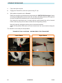
MAINTENANCE PROCEDURE
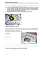
CONTROL VALVE - CAGE
The relief valve is set at 190 Bar and
should be adjusted in accordance with the
setting up procedure.
Remove cap and screw adjusting screw in
to increase pressure and out to decrease
pressure. Put cap back after adjusting.
The diagram below with the manual hand
pump on the left hand side.
All spools used are the same. They are all closed centre in the neutral position. It is critical
that the valve block does not leak internally when in the neutral position. Remember you
have two valve blocks. Each is connected together at the lift cylinders.
If the Ground valve is not leak free, with the spool in the neutral position, when operating the
Cage valve, the oil will not go into the cylinder but leak out (internally) through the Ground
valve. This can also happen if the spool is not properly centralised by the spring at the end of
the spool.
The same thing applies if you operate the Ground controls and the Cage valve is leaking
internally.
The normal symptom for this problem is when the operator reports that “everything works
fine from the ground controls but when operating from the cage, boom x does not move.
Motor runs but nothing happens.” This indicates that the valve which operates the boom is
the valve which is faulty.
23
MAINTENANCE PROCEDURE
CONTROL VALVE - GROUND
Is identical to the cage control valve apart from the following:
x Only 4 sections. Unable to operate the slewing basket from the ground. The slewing
basket is the last spool shown on the cage valve drawing with the two restrictors.
x A high pressure carry over plug has been fitted to the ground control valve to allow oil
under full system pressure to pass through it. Without the internal plug you will not be able
to operate the basket valve as all oil would go directly back to tank.
If you have to replace the ground control valve make sure the carry over plug is fitted. The
plug is inside the valve, under the fitting for the return line. Shine a light down the port and
you will see the Allen head grub screw. If it is not there, use the grub screw fitted to the valve
being replaced.
An oil leak from the valve block it is likely to be from the end cap.
Either the end where the lever is or at the
opposite end where the return spring is.
Never fully withdraw the spool, push it out
opposite to where the leak is coming from
sufficient to clear the “O” ring. Now can pry
out with a small screw driver. Put plenty of
grease and keep well lubricated when
pushing the spool back in.
If the spool is not centring check that the
return spring and the end cap is well
secured.
DIVERTER VALVE
When not activated (no power on the coil) The oil will flow as indicated by the symbols left
hand side.
When activated the oil will flow as shown on the right hand side.
When you look at the complete circuit you will see that with no power on the coil., oil will flow
to the outrigger control valve. Activate the valve and oil flows to the ground control valve. If
you do not get full flow, or you get a high pressure drop over the valve, you may have a
sticking valve . Remove the cartridge form the aluminium body and clean. Also look for
contamination in the valve or the valve cavity.
To check that power is reaching the coil you can hold a screwdriver against the end of the
coil. When the coil is activated you will feel a strong magnetic force pulling the screwdriver
towards the nut securing the coil to the cartridge.
Do not use great force when securing the coil to the
cartridge as the casing can easily crack due to thermal
expansion when it is heated up during use.
The coil will fail if water gets in through the crack.
24
MAINTENANCE PROCEDURE
OUTRIGGER CONTROL VALVE
This valve is not interchangeable with the ground control valve even though it is a 4 bank
valve block with a relief valve and looks identical to the ground controls.
When the spool is in the neutral position the annular side of the ram is attached to the tank
line. This is done to ensure that the pilot pressure holding the check valve on the full bore
open, is drained off quickly to tank so that the check valve close quickly
If the valve block is replaced make sure that the piping is done exactly as shown. You rely on
the closed port as your back up for the check on the full bore side.
Some early version did not have this type of spool. This type can easily be identified as it has
Din-Oil stamped on the end cap. This type used a standard closed centre valve block. The
leakage rate across the closed centre spool was high enough to ensure that the check would
close
Each A port has a restrictive hose adapter
fitted in the valve block. If the restrictor gets
blocked you will not be able to operate the
cylinder correctly.
When looking for a fault relating to
cylinders and valve blocks - swapping hose
connection can easily give a good pointer
to where the fault is. If the fault stays put,
you know that the fault is in the valve block.
If the fault moves you know it is the
cylinder. Do not over tighten the hose
fitting. You are more likely to cause a leak
by deforming the adapter cone than leaving
the fitting to loose.
RESTRICTORS
You have seen that all valve blocks have restrictors fitted at different locations. The most
common version on the current versions (2002) of the TL49K uses a hose adapter with a
drilled hole. Other types which have been in use (and still are on other machines) is a simple
copper washer with a sized hole. The copper washer is squashed between the hose fitting
and the adapter screwed into the valve block.
It is easy to see when a copper washer type restrictor have been used as it looks like the
hose fitting is not screwed fully down onto the adapter when comparing to the hose fitting
next to it. You also need more force when tightening the hose fitting to prevent leaks
Hose adapter shown here with
drilled hole. If cylinder movement is
erratic check for contamination
Copper restrictor fitted loose in the hose
adapter. Hose end require more torque to
prevent oil leak when securing hose.
25
MAINTENANCE PROCEDURE
SLEW MOTOR
The motor is a high torque low speed hydraulic motor. The
motor can be unbolted from the slew drive to check for
leakage. Full seal kit is available with overhaul instructions.
3 and 4 indicate the hoses going to the cage controls.
GENERAL TESTS OF LOAD HOLDING VALVES
You have seen that all critical movements
rely on 2 components for safety
x The lock valve on the cylinder
x The closed centre on the valve block
The valve blocks used have very low leakage rate (that is why we can rely on it for the
slewing cage ram which have no lock valve).
How do you know if you are holding on the valve block and not on the cylinder lock valve ?
With the pump not running. operate the valve block as if you were going to close the ram up.
If there is cylinder movement there is a leaking load holding valve on the cylinder.
Do not use a machine where the load holding valve has failed.
BLEEDING
The hydraulic system needs no special bleeding. Having stripped a cylinder down or
removed hoses for repair, operate the cylinder fully in and fully out and the system is
operational.
SLEWING CAGE RAM
Do not operate the slewing basket ram valve lever without the pump turning. If you operate
the valve lever you can push the basket from side to side. You have now entered air into the
system and the basket will not stay put during transport.
If this should happen, just move the valve lever with the pump running, moving the basket
from side to side will fill the cylinder with oil and the basket will lock in place, when you
release the lever
Warning
Keep it clean - Replace filter and oil regularly - Make sure the oil you put in the tank is
clean - Never fill oil using dirty cans - Remember you use no oil - If you have to
replace oil you have a leak - If you work regularly below 0 deg C and use low viscosity
oil, do not forget to replace the oil for regular grade in the summer to prevent oil leaks
from cylinders and hose ends - Keep a log of relief valve settings to monitor pump
performance - If you have a problem the first thing to do when you arrive is to fit a
pressure gauge to see what is going on. Do not rely on the sound of the pump !
26
MAINTENANCE PROCEDURE
HYDRAULIC PUMP
The engine is driving a hydraulic pump via a spider type coupling.
What to do if loss of oil pressure is experienced and the motor is running correctly?
First check that the hydraulic system is working correctly by checking that the dump valve is
activated. If the dump valve is working and you still have no oil flow, it is most likely to be a
failed pump or that the coupling is spinning on the motor or pump shaft. Remove the bell
housing to check that each coupling half is secured on the shaft. Then remove the pump and
check the internal gears. The Stop/Run/Start key switch is located on the right hand side of
the engine. You also have a separate push button Start/Stop in the cage. Some engines are
equipped with an automatic electrical choke to facilitate remote cold start.
For the engine to start remotely, the key switch on the engine must be in the run position. If
not, the engine will turn over on the starter, but will fail to ignite. The platform’s control circuit
is powered by the engines start battery. The built in heavy duty 10A alternator will recharge
the battery during use. If the engine is not turning over when trying to start the most likely
cause is a discharged battery. Jump start using another 12 volt battery or use the manual
recoil fitted on all engines. Always switch the key switch on the engine to the “Off” position
when not in use to isolate the circuit.
Should the engine turn over without starting check the fuel level first ! Then look at the
electrical circuit for faults.
Always let the engine reach operating temperature before loading the hydraulic
circuit.
Some engines are fitted with a low oil level
safety cut out which will stop the engine and
prevents starting if the oil level is low.
Electrical choke
The engine Stop/Run/Start key switch must
be in the run position even when starting the
engine manually.
HP: 9HP / 3600RPM Max torque 2600RPM
Fuel Capacity : 6 Litres
Pump Capacity : 1.19 cc
Operating RPM : Set to boom speeds !
Noise level : 75db (A)
Max Charging current : 10A
Battery required for manual start : NO
Battery required for platform electrics : YES
Max running time (approximately) : 8 hours
Low oil level cut out fitted : YES
Engine oil spec: SAE 10-40
Check battery weekly and
top up with distilled water if
required
See OEM manual for more information.
27
MAINTENANCE PROCEDURE
ENGINE SETTINGS
THROTTLE
The throttle is locked and must not be tampered
with. If the boom speeds are not in accordance with
the time test sheet the engine speed may have to
be adjusted. Set engine speed by adjusting the
throttle to give required pump flow which in turn
governs boom speed. Then set throttle end stop
and secure throttle from turning using lock nut on
throttle spindle (not shown)
EL. CHOKE
FUEL CUT-OFF
Use fuel cut-off when moving machine over long
distances.
DUMP VALVE
ENGINE OIL SAE 10-40
BATTERY EARTH
TERMINAL
PUMP RELIEF
VALVE
ELECTRICAL START / STOP
The full engine electrical diagram below is not integrated in the main electrical diagram for
the machine. The engine is stopped by letting the signal to the ignition coil go to earth.
28
MAINTENANCE PROCEDURE
LEVEL GAUGE
The level gauge used for setting up the machine
is located next to the outrigger control valve
block. If the level is damaged or has been
removed do not use the machine until a new
level has been fitted.
29
MAINTENANCE PROCEDURE
PHYSICAL DAMAGE
When looking for physical damage it is important that the machine is clean. Large dents in
the boom from operators hitting obstacles are generally easy to see. Crack in welds or
corrosion damage can be harder to spot. The biggest wear and tear is not the load in the
basket but the constant vibration from towing. Curbs and Speed Bumps passed at high
speed can cause severe damage to the tow bar or the axle.
On machines fitted with the optional sliding axle inspect the underside of the axle carrier
and the sliding box suspension. On machine fitted with the fixed axle check the fixing bolts
and the main chassis member. Also check the area just behind the coupling where the
vertical boom is secured to the towbar. If someone has forgotten to secure the vertical
boom to the towbar and towed the machine over a long distance on poor roads damage
may have occurred due to the constant banging of the vertical boom against the towbar.
Also check the top boom rest. The top boom must also be locked in place during
transport.
IMPORTANT
The top boom lock is strictly speaking not needed if the operator always fully
lowers the top boom and powers it down in the rest position. Unfortunately experience on earlier machines has shown that the operator would forget to fully
lower the boom and damage would occur to the underside of the top boom
when it bounced about in its rest during transport. Fitting the top boom lock
greatly reduces the need for top boom repair or possible replacement.
Another area prone to damage is the drop nose. When reversing, the basket may hit a low
wall or a post. The impact may not be easy to spot on an already battered basket but the
impact may bend the bottom of the dropnose.
Check the straightness of the top tie bar. A slight dip is acceptable but a pronounced kink or
sideways bend is unacceptable. Check both booms for creases in the steel next to the main
bosses next to the slew post and the vertical boom.
Hoses and cables are prone to damage and wear and tear. If the outer sheathing on the
hydraulic hose is slightly frayed fitting a temporary outer sleeve may be adequate depending on the size of the damage.
IMPORTANT
Always think of SAFETY FIRST and err on the side of caution If in doubt replace, or ask Snorkel or its local representative for advice .
30
MAINTENANCE PROCEDURE
NUTS & BOLTS
Replace any missing bolts immediately. The main pivot shafts and pivot pins are secured
with one or two locking pegs. The locking peg not only secures the shafts from falling out
but also stops them turning.
Most nuts used are Nyloc nuts which are superior to the normal full nut and spring
washer. Never use plain nuts and spring washers unless originally fitted . Always torque
fixings.
THREAD
SIZE
M4
M5
M6
M8
M10
M12
M14
M16
M20
MAXIMUM TIGHTENING TORQUES
UNPLATED
PLATED
Nm
Lbf.in.
Nm
Lbf.in.
4.6
40.7
3.5
31
9.5
84.1
7.1
62.8
16.0
142.0
12.0
106.0
39.0
345.0
29.0
257.0
77.0
682.0
58.0
513.0
135.0
1200.0
101.0
894.0
215.0
1900.0
161.0
1420.0
330.0
2920.0
248.0
2190.0
650.0
5750.0
488.0
4320.0
31
MAINTENANCE PROCEDURE
LOCKING PEG
Each shaft is secured with a locking peg as mentioned above. If you find
that a peg is broken or that the bolt and peg is missing then this can be a
sign that the shaft is seized due to lack of lubrication. If a seized shaft is
suspected, check that the x-drilling for the locking peg lines up with the bolt
hole for the locking peg securing bolt. Fit a new peg. Carefully operate the
boom to see if the shaft is trying to turn.
If a grease nipple is fitted, apply grease. If you suspect that the shaft is
seized it is recommended to drive the shaft 1/2 way out. Clean and apply
new grease. If the shaft is badly worn or scored, replace both shaft and the
bush.
Depending on which shaft is causing the problem, you may have to support
the structure to prevent jamming when extracting the shaft.
LOCKING PINS
It is important that the boom locking pins
are used when the machine is
transported. Never transport a machine
if the pin is missing. The fixing clips fitted
on current (2002) machines have been
provided to prevent paint damage by the
pin hitting the structure during use.
When towing, insert pin and lock in place
with the “R” clip provided. During
inspection look for indication of the
machine being moved without the pin.
Good tell tale signs are dents in the top
boom and crack lines below the vertical
boom. Contact UpRight or its local agent
on advice for repairs.
32
MAINTENANCE PROCEDURE
TIE DOWN LUGS
Check for wear and tear. Check for damage. You have two lugs attached to each side of the
outriggers. Earlier models had “A” frame towbar with one individual lug welded to each side of
the towbar.
NOTE:
The lugs are for securing the platform when being
stowed or transported, and are NOT designed for
lifting the access platform.
33
MAINTENANCE PROCEDURE
BATTERY & CHARGING
If your machine is fitted with the fully automatic
charger, please read on. If your machine is fitted with a different type, see documentation
which should have been included with the unit.
The Charger has the following advantages:
x Waterproof
x Capable of charging batteries when motor is
running.
x Dual voltage with auto select and indicator
light to show voltage selected.
x Short circuit protection
The Charger (Black Box) shown here with
110V plug. To operate on 240V just
replace plug
x Designed to withstand heavy vibration
x Auto-boost to enable batteries to be kept in
optimum condition when machine is in storage with charger connected.
OPERATION
When connected to the mains supply the output current will be shown in the display window.
With a 2/3 discharged battery the current will be in the region of 25A / 30A.
(Bulk Phase Light On)
When the battery voltage has reached gassing level (2.45V per cell) the timing phase will
start (Gas Phase Light On). This timing period is calculated as follows: 1/2 the time it took to
reach gassing level + 1 hour.
After the timing phase is completed the charger will switch itself into stand-by mode (Charge
Complete Light On)
Take care to properly secure the wires. Burnt terminals indicate loose wires
FUSES :
24V = 15A
Type Bussman Ceramic MDA - (7 or 15)
250Volt, time Delay 1.25” x 0.25”
34
MAINTENANCE PROCEDURE
ERROR CODES
If the display panel on the black box is flickering between –1 and 2 you have a fault in the
transformer or the black box.
Check the two output fuses under the terminal cover. The black box or the transformer
contains no user replaceable parts. Opening the black box apart from the terminal cover
shown will invalidate the warranty. If the Time Out Light comes on you have possibly a faulty
battery. Check each cell with a hydrometer. The Time Out light will come on and the charger
will switch off if gassing level has not been reached in 24hours.
Reverse Polarity Light will light if the output cables to the battery are reversed. Red Cable
Must go to + battery terminal, Black Cable must go to - battery terminal.
CHARGING TIMES
The charger will recharge 2/3 discharged batteries in 8 to 10 hours. In reality batteries are
often discharged more than 2/3 when used on a access platform. The operator tend to use
the machine until the motor stops (This causes arcing of the motor contactor, and severe
heat rise in the motor. Both of which shortens the components life considerably.) Then he
forgets to put the machine back on charge until after the weekend. The result is that the
battery can be as much as 95% discharge before the charger is connected (this causes
severe reduction in battery life). If the battery cell voltage is below 1 volt the charger may not
start. In that case, hold down the low voltage start button for several seconds. This will
bypass the charger safety system and cause it to start irrespective of battery voltage. After
the voltage has increased sufficiently for the controller to take over, you can let go of the
button.
If gassing level is not reached in 24hours the charger will switch off and the Time Out Light
will come on. Disconnecting the input lead will automatically re-set the timer. Take care not
to disconnect the charger during a charging cycle. Always let the charger reach “Charge
Complete” or “Time Out” to prevent overcharging.
PRACTICAL APPLICATIONS
The operator will run the batteries all the way down. Then he will try to connect the charger
and continue working the machine. This will not work. The electric motor requires as much as
3 times the charger output. The charger will float on max 30A and the motor will not turn
(This results in damage to the motor and contactor)
If the user has a very hectic work schedule he may run out of battery power before he has
finished his work. In that case he can connect the charger to a mains supply before the
batteries are 50% discharged. This will then give enough time for the charger to keep topping
up the batteries and extend the duty cycle of the machine considerably.
The battery life may be slightly reduced as the optimum charging cycle for any battery is
“fully charged - 2/3 discharged and then fully charged”
35
MAINTENANCE PROCEDURE
MAINTENANCE
x Check that the fuses are secured in the fuse holder.
x Check that all wires are secure on the terminal block and on the battery terminal.
x Check that the multi-pin plug is secure on the pcb.
x Check for damage to cables and wiring.
BATTERY
When charging the battery will give off explosive hydrogen gas. Keep away from open
flames. Always wear appropriate personal safety equipments such as eye protection and
rubber gloves to prevent injury in case of spillage.
Keep the top of the batteries clean and free from dirt. It is very easy for the battery to be
contaminated when topping up with distilled water. The batteries are working very hard and
regular topping up with distilled water will be required.
PRACTICAL APPLICATIONS
The most common problem is the operator complaining that
“The machine has just gone out on hire and did only 2 lifts - and yes we did have it on
charge all last night before it went out”
You need to establish:
x Was the charger working ?
x Are the batteries in good condition ?
The most useful tool you can have is the Hydrometer ,to check the specific gravity, and a
simple volt meter. Check each cell and see how they all compare. If one or more cell is
significantly lower than the rest, replace all batteries. It is false economy to replace individual
batteries.
To check if the charger works you can connect your voltmeter to the same battery terminals
as the charger. Take a note of the reading. Now connect the charger to mains voltage.
You should see a marked increase in voltage. Also check the display on the charger. You
can also connect an inline ammeter (or use a clamp on type) to check that the charger output
display matches the current going into the batteries
BATTERY CHARGING USING GENERATOR
The charger can only be connected to a generator fitted with a full AVR (Automatic Voltage
Regulator) and spike filtering system.
Large voltage fluctuations and spikes will damage the electronic components in the charger
We have found that the Honda Generator sets offer the best and most reliable voltage
supply. This applies only to the fully integrated Honda generator sets and not the cheaper
verity using a Honda Engine fitted with a non Honda generator unit.
36
MAINTENANCE PROCEDURE
ELECTRICAL SYSTEM
The electrical system is quite simple and requires minimal maintenance. The biggest
problem is loose connections, again caused by vibration during towing, and the second is
moisture or condensation caused by high humidity and temperature fluctuations.
Erratic running of the motor when depressing the green run button and moving the booms
can be caused by an intermittent internal cable failure. The failure can be hard to locate. The
best way is to lower the relevant boom. If the motor has stopped permanently, use the
emergency lower system. Try to raise the boom again and see it the fault occurs roughly in
the same place. If it does, it is highly likely you have an internal cable failure and the
complete cable should be replaced.
On mains powered machine the control circuit is almost identical apart from voltage variants
and the use of a isolation transformer on the control circuit. The bolt on motor contactor
used on the DC pack is replaced by a combined thermal overload and motor contactor
mounted inside its own junction box. On I.C. machines the boom circuit is the same as for
the DC powered machines apart from the electrical start stop circuit needed for the engine.
EMERGENCY STOP
Two emergency Stops are fitted. One at each control post. When depressed they must stop
all movements within a few seconds maximum. When activated it must not be possible to
operate the machine. To release, turn 1/4 turn and the Emergency stop head will pop back
out.
The switch head is not physically attached to the switch mechanism behind the head. If the
head is released and the machine will not start check that the switch has not seized in the
open position.
37
MAINTENANCE PROCEDURE
STABILISER LIMIT SWITCHES
(OUTRIGGERS)
4A CB
PB4
MOTOR
RUN OUTR.
PB1
ESTOP
BOOM
LIMIT
SWITCH
CAGE CONTROLS
+24V
PB6
Cage
OFF
ESTOP
1 02
GROUND
1
2
2
2
1
MOTOR RUN
PB7
SW2 Cage/Ground
PB2
AWD
MOTOR RUN
F1
200A
RL2
LP2
LP3
LP4
LP5
CT1
SOL1
M1
0V
CT1 is mounted on top of the DC motor and switches the motor on/off
CB is a 4A Re-settable circuit breaker to protect the wiring loom from damage in case of a
short circuit.
PB1 is the first emergency stop. Mounted on the ground controls.
SW2 is the key switch for selecting Cage or Ground controls and operating the outriggers.
Turn to cage and switch set 1 closes. Turn to ground and switch set 2 closes
RL2 remains closed until the outriggers are under pressure.
AWD is the audible alarm fitted in the cage control box. The alarm is controlled by RL2.
PB4 is the black motor run switch on the ground control only used to start the motor when
operating the outriggers.
Boom Limit Switch must be closed and the booms down to enable the motor to start and
operate the outriggers.
Outrigger limit switch contain 2 N.C. contactor. One set controls the 4 LED’s LP2-LP5.
The other set is wired in series. When all the switches are closed, RL2 is activated. AWD
stops
38
MAINTENANCE PROCEDURE
PB2 is the green motor run button on the ground controls. This switch becomes active
after the SW2 is turned to ground and the 4 outrigger limit switches are closed.
SOL1 is the coil on the hydraulic diverter valve. When activated it prevents oil going to
the outrigger control valve. It must be activated for the boom functions to work.
PB6 is the emergency stop button in the cage.
PB7 is the Green motor run button in the cage. After the key switch is turned to cage and
the 4 outriggers are under pressure (PB6 not activated) pressing PB7 starts the motor.
SOL1 is pulled in and the oil will flow to the cage control valve.
All wires are numbered as shown. Each wire terminal has the same number as the cable
attached to it.
You will not be able to raise the outriggers unless the boom limit switches are activated as
it is only PB4 which starts the electric motor without activating SOL1.
F1 protects the power side to the electric motor.
The battery can be isolated by pulling the Anderson plug next to the power pack
39
MAINTENANCE PROCEDURE
x The outriggers should be inoperable when the booms raise. If they can be operated,
check the boom limit switch and the diverter valve. If the outriggers are inoperable with the
booms lowered, check the boom limit switch and the diverter valve
x If the emergency lowering valve on the top or bottom
ram has been operated, fully extend the cylinder to
fill the ram up with oil. Delay for several seconds the
first time the cylinder is powered down, to allow it to
fill with oil.
x To operate the emergency slew handle, the slew
valve handle must be operated at the same time,
allowing the oil to circulate.
x Check that the audible alarm is working. It should
activate when a light leg is on.
x The booms are inoperable unless the outriggers are
all down and in full contact with the ground. If the
booms are operable, adjust the outrigger limit switch
immediately. If the outrigger are set incorrectly the
platform could become unstable.
A light leg
activating during use, will stop the machine and an
audible alarm will sound. This is mounted on the
underside of the cage control box. The hand pump
must be operated to lower the platform and the
outriggers re-set. Check that the LED on the ground
control panel is working correctly. Each LED should
only come on when the associated outrigger is in
contact with the ground
40
MAINTENANCE PROCEDURE
WHEELS
Check for damage to the tyre. Replace if tread pattern is worn below 3mm. On machines with
sliding axle you will see increased wear on the inside part of the tyre compared to the outside
part. It is important that correct tyre pressure is maintained at all times. The correct pressure
is 5.2bar (76PSI) and not what may be indicated on the tyre. See separate tyre pressure
decal fitted to the top of the mudguard. Tyre size is : 215/75 R16 8ply.
IMPORTANT
For fully service and maintenance information on the running gear contact Snorkel and
request a copy of the running gear OEM service handbook. Below are a few important
extracts which covers the some of the basic checks to carry out when servicing the
machine. If the handbrake is not fully applied there is a risk that the trailer could run
backwards. The brake rod must not be under tension or bowed when the
handbrake is disengaged.
BRAKES
Check Bowden cable for damage - Replace if inner steel core is visible. Sticking brakes can
be down to seized cables. The inner steel wire must run freely inside the cable.
Adjust the brakes with the wheels removed. Remove
the plastic bung in the back of the brake plate. Use a
screw driver to adjust the star wheel until resistance is
felt when turning the brake drum in the direction of
travel. Then slack back until the brake drum turns
freely.
Check for correct movement of the Bowden cable.
The cable should move 5 to 8 mm. Check for uniform
response when braking. All adjustment must be done
at the wheel brake and not on the brake linkage.
When removing the drum for cleaning the brake shoes. Always ensure that a new flanged
nut is used. Tighten the flange nut to 280Nm - 300Nm. When refitting the wheel, tighten
wheel nuts in the N.S.W.E sequence and to a torque of 88Nm.
AXLE
The axle is fully maintenance free. Check fixing bolts. If ordering replacement axle quote all
ref. numbers on the oval serial number plate riveted to the axle beam.
41
MAINTENANCE PROCEDURE
COUPLING / OVERUN DEVICE
draw bar
compensator
brake
Ensure that the draw bar is fully extended. Screw the brake rod into the pivot head and
secure with a M10 nut. Using the M10 ball nut, connect the brake rod to the Bowden cable
via the compensating bracket. Fit and hand tighten the hex securing nut. Tighten the M10
ball nut on the brake rod until there is no further play on the pivot head against the draw bar
(the draw bar must be fully extended).
The compensating bracket must be square on the brake rod. The current type of Bowden
cables are non adjustable. Hook the cable on to the compensator bracket . Adjust to ensure
even braking on the brake, not on the compensator.
Check that both wheels run freely in the forward direction. Apply handbrake, the brakes
should start to come on at the second click. The gas strut will ensure that the handbrake is
fully applied. If the trailer is moving backwards the handbrake will move further up. This is
normal. It is imperative that the gas strut is working correctly. Without the gas strut the
brakes will not hold the trailer on a slope.
Adjust brakes if required.
Check that all nuts are secure.
Grease the coupling head.
Multipurpose grease to DIN 51825 KTA 3K
Clean and oil all other moving parts.
WHEEL BEARINGS
The wheel bearings are sealed for life and require no maintenance or grease. The service life
for a set of bearings is in the region of 20, 000 to 30, 000 miles, depending on running
conditions. It is vital that the brakes have not been overheated as this will cause the grease
in the sealed ball bearings to evaporate and the bearings will fail.
Never re-use the flanged nut when refitting the brake drum as the wheel may come off when
towing
When purchasing a brake drum the bearings are normally included, fitted to the brake drum.
If replacing bearings only, contact Snorkel or its local representative for further information.
Always use a new flanged nut and torque to 280—300Nm when refitting the drum.
42
MAINTENANCE PROCEDURE
13 PIN CONNECTOR
8
9
7
1
10
2
3
11
12
LEFT H/S
= Not Used.
5
13
RIGHT H/S
+
-
-
2 Core Cable
2 Core Cable
+
6
4
RH Registration
Lamp
LH Registration
Lamp
13 PIN CONNECTOR
PIN
1
2
3
4
5
6
7
8
9
10
11
12
13
FUNCTION
LH INDICATOR
FOG LAMP
NEGITIVE
RH INDICATOR
RH TAIL LAMP
BRAKE LAMP
LH TAIL LAMP
REVERSING LAMP
NOT USED
NOT USED
NOT USED
NOT USED
NOT USED
COLOUR
YELLOW
BLUE
WHITE
GREEN
BROWN
RED
BLACK
DARK BLUE
N/A
N/A
N/A
N/A
N/A
43
MAINTENANCE PROCEDURE
GENERAL GREASE POINTS
Regular greasing not only greatly improves the service life of the bushes, it also will remove
any moisture which may cause internal corrosion on the wall of the bosses making it difficult
to remove the pivot shafts for inspection.
LUBRICATION SPECIFICATIONS
We recommend only using premium quality grease. Experience has shown that a Lithium
based grease offers very good performance. For the slew ring the RENOLIT ARMNA
G4789 from Fuchs offers extremely good lubrication and anti corrosion properties.
Especially at very low temperatures (-30DegC)
SLEW DRIVE
To grease the slew ring you must set
the machine up and slew around so
you can gain access to the reassessed grease nipple fitted to the top
face of the slew ring.
When greasing the worm housing
take care not to push out the oil seal
on the end face. If you do, remove
excess grease from the end and drive
the seal back in.. See Slew Drive
Gear section for more details.
44
MAINTENANCE PROCEDURE
SLEW DRIVE GEARS
The slew drive gear is designed to be
largely maintenance free. However, we
recommend the gear teeth be greased
on a weekly / monthly basis with a high
pressure grease depending on
operating conditions. Always clean the
gear first to remove any road dirt and
grime. In very dusty or sandy conditions
take care to prevent a build-up of grit /
sand mixed with grease which may
cause premature wear on the gear.
Additionally, the ring gear and gear box should be greased on a six monthly basis. The
grease nipple for the ring gear is on the top face of the slew gear, set between the fixing
bolts. It can be accessed by lifting one of the side covers, and slewing the structure appropriately.
The ring gear should be inspected on a six monthly basis for excessive play. It is unlikely
there will be any wear if the machine is maintained correctly.
To check the gear, place a payload of approximately 80Kg in the platform. Elevate the lower
boom to approximately half way. Then gently elevate the top boom, whilst observing the
ring gear. Excessive wear will be observed by noticing more than 0.5mm movement between the inner and outer bearing rings. If excessive wear is present the gear ring should
be replaced
45
MAINTENANCE PROCEDURE
The slew stop mechanism is fully lubricated and should normally not require any further lubrication. Should more lubrication be needed this can be done in two ways.
1)
2)
3)
When greasing the slew bearing some grease will drop in to the centre part of the slew.
Keep on greasing the slew bearing until the grease escapes from the outside sealing
lip on the slew gear. Continue greasing, as the grease will now be pushed out through
the outer and inner sealing ring of the slew bearing.
Grease escaping from the inner seal will drop onto the slew stop ring.
Also spray LPS-3 lubrication up between the Slew tube and the chassis plate.
Slew tube
Spray LPS-3 in
between the
tube and the
chassis plate
How does the slew stop work ?
The slew stop mechanism is very simple and prevent the cables and hoses getting tangled
up by continuous rotation. The Slew stop ring will allow the operator to turn almost 360 deg
in each direction from the stowed position.
The critical parts of the slew stop are as follows :
Chassis stop
Slew stop ring tab
Slew stop ring
Slew stop ring tab
Slew tube stop
Slew stop ring
Chassis stop
When slewing (rotating) the Slew tube stop will pick up on the Slew stop ring tab and drag it
around until Slew stop ring tab hits the Chassis stop. The platform can now slew almost
two turns in the opposite direction until the Slew stop ring tab hits the Chassis stop. This
gives you almost two turns “lock to lock”. From the parking position this equates to “one
turn left or one turn right” measured from the parking position
46
MAINTENANCE PROCEDURE
What can go wrong ?
The mechanism is very simple and has proven
reliable in the field. However If the slew does
not stop, check that one of the 3 steel stop
blocks has broken loose.
If this is not rectified the platform can slew continually and will rip out the hoses and cables. To
solve this problem, split the machine and reweld the slew stop.
Slew tube stop
Check hydraulic pressure. Apply plenty of lubrication to ensure that the slew stop ring has
not got jammed. Again if the problem does not disappear you have to split the machine to
investigate further.
IMPORTANT
THOROUGH INSPECTION
All machines being operated in the UK must have a thorough inspection
carried out every 6 months in accordance with LOLER Regulations 1998
and a Certificate of Thorough Inspection produced by a competent person.
When the machine has passed its test the machine will be issued with a
sticker showing the Certificate number and the date of next Examination. A
copy of the Certificate is available upon request.
Contact Snorkel for further details
47
Illustrated Parts List
CONTENTS
Page Number
Illustrated Mechanical Parts List
2
Electrical Parts List
27
Hydraulic Hose and Fittings Lists
29
Electrical Schematics
Battery Power
Mains Power
Diesel/Petrol
Bi-Fuel Power
33
34
35
36
Battery/Mains Power
Diesel/Petrol
Bi-Fuel Power
Friction Drive Option
37
38
39
40
Hydraulic Schematics
513868-200
Page 1
Illustrated Parts List
LIGHTING BOARD ASSEMBLY
1
1
4
2
3
4
5
6
7
8
Lighting Board Assembly
Item
1
2
3
4
5
6
7
8
Part No.
Description
512492-000
513301-000
513302-000
513742-000
513300-000
058490-016
056069-005
Qty.
2
1
1
2
2
4
8
8
AMBER REFLECTOR
RH LIGHT CLUSTER
LH LIGHT CLUSTER
REGISTRATION LAMP MOUNTS
REGISTRATION LAMP
SET SCREW, M5 x 16mm
M5 FLAT WASHER
056066-005
M5 NYLOCK NUT
Marker Lamp Kit (NOT SHOWN)
Part No.
513836-000
513836-001
513839-000
513838-000
513492-000
513403-000
512687-000
512689-000
Page 2
Description
Harness, Tow Hitch to Chassis
Harness, Chassis to Side Marker Lamps
Harness, Rear Light to Registration Lamp
Harness, Rear Light to Side Marker Lamp
Amber Marker Lamp
White Reflector
13 Pin Plug
8 Core Cable
513868-200
Qty.
1
1
2
2
6
2
1
10m
Illustrated Parts List
OUTRIGGER COMPONENTS
Outrigger Components
Item
Part No.
Description
1
10-5069
Outrigger
4
2
10-5070
Outrigger Foot
4
3
13-3608
Outrigger Ram
4
4
22-5179
Outrigger Ram Cover
4
5
15-0886
Ram Cover Skid Pad
4
6
12-2054
Banjo Bolt
8
7
SB-030030
Bush
24
8
SP-016E216
Pin
4
9
SP-030D171
Pin
4
10
SP-030D203
Pin
4
11
SP-030K211
Pin
4
12
10-2672
Retaining Peg
16
513868-200
Qty.
Page 3
Illustrated Parts List
2
9
10
3
8
13
11
15
16
14
7
6
24
17
25
21
4
20
22
23
19
1
5
26
27
18
28
12
CHASSIS COMPONENTS
Page 4
513868-200
Illustrated Parts List
CHASSIS COMPONENTS
Chassis Components
Item
1
2
3
4
5
6
7
8
9
10
11
12
13
14
15
16
17
18
19
20
21
22
23
24
25
26
27
28
Part No.
Description
Qty.
513439-000
508106-000
508107-000
513441-000
513443-000
03 0275/01
03-0275/02
24-3998
21-0855
10-5068
09-1273
09-1394
513398-000
513397-000
508133-000
508134-000
508112-000
513450-000
513449-000
513416-000
513793-000
IT250
11-3449
08-0192
10-5271
13-2537
25-0239
513403-000
513492-000
513522-002
513522-000
513522-001
Chassis
Towing Coupling
Adjustable Jockey Wheel
3000Kg Rubber Suspension Axle c/w Brake Cables
215/75R16 Wheel Assembley (5 Stud)
Wheel Studs
Wheel Nuts
Brake Rod
Boom Retaining Pin
Boom Lock
Inlet Plug
Inlet Plug Cap
Cycle guard R/H
Cycle guard L/H
Bowden Cable
Cable Bracket
NATO Plug
Mudguard Support Bracket L/H
Mudguard Support Bracket R/H
Mudguard Mount Bracket
Mudguard Mount Bracket (Friction Drive units only)
Mudguard
Bolt (M12 x 80mm)
Slew Bearing/worm Drive c/w Motor
Slew Limiting Ring
Stabiliser Control Valve
Levelling Bubble
White Marker Lamp
Amber Marker Lamp
Mudflap Bracket
Mudflap
Mudflap Support Bracket
1
1
1
1
2
10
10
1
1
1
1
1
1
1
1
1
1
1
1
2
2
2
26
1
1
1
1
2
6
Brake Hub Components
Part No.
14305.08
DPSM 63 90 10
368A / 362A
LM501349 / 501310
24929.03
1053 08
Description
Knott 300 x 60 Std. Brake Assembly
Oil Seal
Inner Bearing Cone/Cup
Outer Bearing Cone/Cup
Standard Brake Shoe
Load Washer
513868-200
Qty.
2
2
2
2
2
2
Page 5
Illustrated Parts List
SLEW COMPONENTS (BI-FUEL POWER)
Slew Components (Bi-Fuel Powered Machine)
Item
Part No.
Description
1
2
3
4
5
6
7
10-5071
16-0147
16-0148
15-0858
24-4097
10-5266
10-5267
Slew Platform
GRP Cover
GRP Cover
Hinge
Cover Stay
Power-pack Tray
Battery Tray
22-5576
09-1185
TA0064-2639
09-2280
19-0 154/2
19-0154/1
19-0154
09-0998
13-3609
02-2639
22-5581
13-0888
11-3448
10-2672
24-2880
SP-035D320
21-0852
2-5577
20-0055
13-0529
13-1949
13-1950
13-3649
13-3650
13-3651
10-5269
10-5270
09-1009
11-3438
22-5177
09-1393
13-0146
Cross Brace
Battery 6v
Battery Power Connectors
Platform Charger/Transformer Module
Hand-pump Handle
Hand-pump
Power-pack
Contactor
Hydraulics Manifold
Electrical Control Box (Parts list
Control Box Cover
Base Control Valve
Bolt (M12 x 85mm)
Retaining Peg
Retaining Peg - Large
Pin
Pin
Splash Guard
Kubota OC60 diesel engine c/w stop/start kit
In-Line Check Valve
Bell Housing
Flexible Coupling
Pump
Outlet Elbow
Suction Elbow
Engine Mounting Bracket
Battery/Pump Cover
Battery 12v
Clamp Plate
Battery Clamp Rod
230vPlug
3-way Valve
Engine Jump-start Battery Kit
Battery Disconnect Connector, Female
Battery Disconnect Connector, Male
Battery Disconnect Connector, Handle
Hydraulic Tank Drain Kit
8
9
10
11
12
13
14
15
16
17
18
19
20
21
22
23
24
25
26
27
28
29
30
31
32
33
34
35
36
37
38
39
40
41
Page 6
G70241
G70242
G70243
508136-000
Qty.
1
1
1
4
2
1
1
513868-000
1
4
2
1
1
1
1
1
1
1
1
1
28
2
2
1
2
1
1
2
1
1
1
1
1
1
1
1
2
2
1
1
1
1
1
1
1
Illustrated Parts List
SLEW COMPONENTS (BI-FUEL POWER)
513868-200
Page 7
Illustrated Parts List
SLEW COMPONENTS (MAINS POWER)
Item
1
2
3
4
5
6
7
8
9
10
11
12
13
14
15
16
17
18
19
20
21
22
23
24
25
26
Page 8
Part No.
10-5071
16-0147
16-0148
15-0858
24-4097
10-5266
10-5267
22-5576
19-0155
19-0154/2
19-0154/1
22-5516
09-1937
13-3609
22-5581
13-0888
11-3448
10-2672
24-2880
SP-035D320
21-0852
22-5508
09-2087
Slew Components (Mains Powered Machine)
Description
Slew Platform
GRP Cover
GRP Cover
Hinge
Cover Stay
Powerpack Tray
Battery Tray
Cross Brace
Ballast Plate
230V Control Box
Powerpack
Handpump Handle
Handpump
Float Charger Cover
Float Charger
Hydraulics Manifold
Slew Control Box
Control Box Cover
Base Control Valve
Bolt
Retaining Peg
Retaining Peg - Large
Pin
Pin
Emergency Battery Holder
Dry Battery
513868-200
Qty.
1
1
1
4
2
1
1
1
2
1
1
1
1
1
1
1
1
1
1
28
2
2
1
2
1
1
Illustrated Parts List
SLEW COMPONENTS (BATTERY POWER)
Item
1
2
3
4
5
6
7
8
9
10
11
12
13
14
15
16
17
18
19
20
21
22
23
24
25
26
27
Part No.
10-5071
16-0147
16-0148
15-0858
24-4097
10-5266
10-5267
22-5576
09-1185
09-1663
09-1665
19-0154
19-0154/2
19-0154/1
22-5577
09-0998
13-3609
22-5581
13-0888
11-3448
10-2672
24-2880
SP-035D320
21-0852
11-3438
22-5177
Slew Components (Battery Powered Machine)
Description
Slew Platform
GRP Cover
GRP Cover
Hinge
Cover Stay
Powerpack Tray
Battery Tray
Cross Brace
Battery
Charger Power Module
Transformer
Powerpack
Handpump Handle
Handpump
Splash Guard
Contactor
Hydraulics Manifold
Slew Control Box
Control Box Cover
Base Control Valve
Bolt
Retaining Peg
Retaining Peg - Large
Pin
P in
Clamp Plate
Battery Clamp Rod
513868-200
Qty.
1
1
1
4
2
1
1
1
4
1
1
1
1
1
1
1
1
1
1
1
28
2
2
1
2
2
2
Page 9
Illustrated Parts List
SLEW COMPONENTS (ENGINE POWER)
Item
1
2
3
4
5
6
7
8
9
10
11
12
13
14
15
16
17
18
19
20
21
22
23
24
25
26
26
27
28
29
30
31
32
33
34
35
Page 10
Part No.
10-5071
16-0147
16-0148
15-0858
24-4097
10-5266
10-5267
22-5576
HS03
10-5310
19-0154/2
19-0154/1
13-0339
13-2543
13-3609
22-5581
13-0888
11-3448
10-2672
24-2880
SP-035D320
21-0852
22-5613
20-0044
20-0055
13-0529
13-1949
13-1950
13-3649
13-3650
13-3651
10-5269
10-5270
09-1009
Slew Components (Engine Powered Machine)
Description
Slew Platform
GRP Cover
GRP Cover
Hinge
Cover Stay
Powerpack Tray
Battery Tray
Cross Brace
Ballast Plate
Sight Gauge
Hydraulic Tank
Handpump Handle
Handpump
Suction Strainer
Return Line Filter
Hydraulics Manifold
Slew Control Box
Control Box Cover
Base Control Valve
Bolt
Retaining Peg
Retaining Peg - Large
Pin
Pin
Tank Lid
Engine (Petrol)
Engine (Diesel)
In-Line Check Valve
Bell Housing
Flexible Coupling
Pump
Outlet Elbow
Suction Elbow
Engine Mounting Bracket
Battery/Pump Cover
Battery
513868-200
Qty.
1
1
1
4
2
1
1
1
2
1
1
1
1
1
1
1
1
1
1
28
2
2
1
2
1
1
1
2
1
1
1
1
1
1
1
1
Illustrated Parts List
SLEW COMPONENTS (ENGINE POWER)
513868-200
Page 11
Illustrated Parts List
LOWER BOOM COMPONENTS
Lower Boom Components
Item
1
2
3
4
5
6
7
8
9
10
11
12
13
14
15
16
17
18
19
20
Page 12
Part No.
Description
Qty.
10-5072
10-5073
10-5263
13-3607
13-3606
13-3604
21-0852
SP-035D201
21-0850
SP-030D320
SP-035D320
Bottom Boom
Tie Bar
Vertical Boom
Bottom Ram
Top Ram
Master Ram
Pin
Pin
Pin
Pin
Pin
1
1
1
1
1
1
2
1
1
1
1
SB-060060
SB-035035
SB-030030
SB-025025
10-2672
24-2880
15-0884
15-0883
Bush
Bush
Bush
Bush
Retaining Peg
Retaining Peg
Boom Rest Pad
Boom Rest Pad
8
6
2
2
8
2
1
1
513868-200
Illustrated Parts List
TOP BOOM COMPONENTS
Top Boom Components
Item
1
2
3
4
5
6
7
8
9
10
11
12
13
14
15
16
17
18
19
20
21
22
23
24
25
Part No.
10-5075
10-5076
13-3603
13-3605
15-0899
15-0881
15-0880
15-0895
15-0896
15-0882
24-3952
10-5138
SP-035D203
SP-025D200
SP-040D203
SP-025A120
SP-025D164
10-2672
SB-030030
SB-040040
SB-025025
09-2121
24-3909
15-0883
15-1009
Description
Top Boom
Telescopic Boom
Cage Levelling Ram
Telescope Ram
Tele Ram Support Block
Wear Pad
Wear Pad
Wear Pad
Wear Pad
Wear Pad
Pad Retaining Nut
Wear Pad Keep Plate
Pin
Pin
Pin
Pin
Pin
Retaining Peg
Bush
Bush
Bush
Cable Tray
Hose Trunking
Boom Rest Pad
Drag-chain Complete
513868-200
Qty.
1
1
1
1
1
1
6
1
1
2
8
4
1
1
1
1
1
8
2
2
4
1
1
1
1
Page 13
Illustrated Parts List
DROPNOSE COMPONENTS
Drop-nose Components
Item
1
2
3
4
5
6
7
Page 14
Part No.
10-5078
10-5077
13-3602
SP-025D200
SP-030D216
10-2672
SB-025025
Description
Drop-nose Boom
Quadrant
Drop-nose Ram
Pin
Pin
Retaining Peg
Bush
513868-200
Qty.
2
1
1
3
1
6
12
Illustrated Parts List
CAGE SUPPORT COMPONENTS
Cage Support Components
Item
1
2
3
4
5
6
7
8
9
10
11
12
13
14
15
Part No.
Description
Qty.
10-5232
10-5231
10-5229
10-5230
SP-025D235
SP-025D330
SP-016B108
10-2672
SB-025015
SB-025025
SB-016020
04-0113
13-2403
23-0031
11-3442
Pivot Support
Cage Slew Pivot
See-Saw Bracket
Upper Link Bracket
Pin
Pin
Pin
Retaining Peg
Bush
Bush
Bush
Thrust Washer
Cage Rotation Ram
Spring
Bolt (M12 x 170mm)
513868-200
1
1
1
1
4
1
1
9
8
2
4
2
1
2
2
Page 15
Illustrated Parts List
STEEL CAGE COMPONENTS
Page 16
513868-200
Illustrated Parts List
STEEL CAGE COMPONENTS
Steel Cage Components
Item
Part No.
Description
Qty.
1
2
3
4
5
6
7
8
9
10
11
12
13
14
15
10-5201
22-5065
11-3438
508932-000
508934-000
SP-016B102
10-2672
10-5206
13-0176
13-2200
22-5370
22-5601
09-1276
22-5543
508140-000
S te e l C a g e
Cage Floor
C l a mp P l a te
U-Clamp
Access Bar
Pin
Retaining Peg
Control Support
Double Over-centre Valve
Control Valve
Rear Cover
Blanking Plate
Socket (110V)
Control Support Top Plate (Battery & Engine Powered)
RCD
1
1
5
2
1
1
1
1
1
1
1
1
1
1
1
16
09-2126
Amber Marker Lamp
2
17
09-1939
Swivel Light
2
508158-001
Page 17
Illustrated Parts List
GRP BASKET COMPONENTS
GRP Basket Components
Item
1
2
3
Part No.
02-2674
22-5603
10-5317
Description
GRP Basket
Access Guard
Basket Support
Qty.
1
1
1
4
SP-016B102 Pin
1
5
6
7
8
10-2672
10-5206
13-0176
13-2200
Retaining Peg
Control Support
Double Overcentre Valve
Control Valve
1
1
1
1
9
22-5370
Rear Cover
1
10
11
11
12
12
12
22-5601
09-1276
09-1392
22-5543
22-5542
22-5544
Blanking Plate
Socket (110V)
Socket (230V)
Control Support Top Plate (Battery & Engine Powered)
Control Support Top Plate (Mains Powered)
Control Support Top Plate (Mains Powered c/w Generator)
1
1
1
1
1
1
Page 18
513868-200
Illustrated Parts List
OUTRIGGER RAM COMPONENTS
Outrigger Ram - 13-3608
Item
1
2
3
4
5
6
7
8
Part No.
Description
13-3608-1
13-2351
13-1004
13-0604
13-0973
13-1007
SS-0400023
13-3608-2
Tube Assembly
Seal Kit
Head Bush
PO Check Valve
Locknut
Piston
Spacer
Rod Assembly
Qty.
1
1
1
2
1
1
1
1
513868-200
Page 19
Illustrated Parts List
BOTTOM RAM COMPONENTS
Bottom Ram - 13-3607
Item
1
2
3
4
5
6
7
8
9
10
11
Page 20
Part No.
13-3607-1
13-0972
13-0968
13-0392
13-2474/2
09-2090
13-2425/77
13-0973
13-0971
SS-0500343
13-3607-2
Description
Tube Assembly
Seal Kit
Head Bush
Over-centre Valve
Emergency Lower Valve
Solenoid
Hirschmann Connector
Locknut
Piston
Spacer
Rod Assembly
513868-200
Qty.
1
1
1
1
1
1
1
1
1
1
1
Illustrated Parts List
TOP RAM COMPONENTS
Top Ram - 13-3606
Item Part No.
1
2
3
4
5
6
7
8
9
10
11
12
13-3606-1
13-0972
13-0968
13-0392
13-2474/2
09-2090
13-2425/77
13-0973
13-0971
SS-0500037
13-3606-2
13-3606-3
Description
Qty.
Tube Assembly
Seal Kit
Head Bush
Over-centre Valve
Emergency Lower Valve
Solenoid
Hirschmann Connector
Locknut
Piston
Spacer
Rod
Bearing
513868-200
1
1
1
1
1
1
1
1
1
1
1
1
Page 21
Illustrated Parts List
MASTER RAM COMPONENTS
Master Ram - 13-3604
Item
1
2
3
4
5
6
Page 22
Part No.
Description
13-3604-1
13-3603-3
13-1061
13-0973
13-1064
13-3604-2
Tube Assembly
Seal Kit
Head Bush
Locknut
Piston
Rod Assembly
Qty.
1
1
1
1
1
1
513868-200
Illustrated Parts List
TELESCOPE RAM COMPONENTS
Telescope Ram - 13-3605
Item Part No.
1
2
3
4
5
6
7
8
9
13-3605-1
13-3605-3
13-3605-4
13-0472
13-0659
13-3605-5
13-3605-6
13-3605-7
13-3605-2
Description
Qty.
Tube Assembly
Seal Kit
Head Bush
Over-centre Valve
PO Check Valve
Piston
Locknut
Spacer
Rod Assembly
1
1
1
1
1
1
1
1
1
513868-200
Page 23
Illustrated Parts List
LEVELLING RAM COMPONENTS
Levelling Ram - 13-3603
Item
1
2
3
4
5
6
7
Page 24
Part No.
13-3603-1
13-3603-3
13-1061
13-2489
13-1064
13-0973
13-3603-2
Description
Tube Assembly
Seal Kit
Head Bush
Over-centre Valve
Piston
Locknut
Rod Assembly
Qty.
1
1
1
2
1
1
1
513868-200
Illustrated Parts List
DROPNOSE RAM COMPONENTS
Drop-nose Ram - 13-3602
Item
1
2
3
4
5
6
7
8
Part No.
13-3602-1
13-3603-3
13-1061
13-2489
13-1064
13-0973
13-3602-3
13-3602-2
Description
Tube Assembly
Seal Kit
Head Bush
Over-centre Valve
Piston
Locknut
Spacer
Rod Assembly
Qty.
1
1
1
2
1
1
1
1
513868-200
Page 25
Illustrated Parts List
CAGE ROTATION RAM COMPONENTS
Cage Rotation Ram - 13-2403
Item
1
2
3
4
5
6
7
Page 26
Part No.
13-2403-1
13-0993
13-0988
13-0992
13-0994
SS-0200020
13-2403-2
Description
Tube Assembly
Seal Kit
Head Bush
Piston
Locknut
Spacer
Rod Assembly
Qty.
1
1
1
1
1
1
1
513868-200
Illustrated Parts List
Electrical Parts Kit 02-2639
Location
Control Box
Control Box
Control Box
Control Box
Control Box
Control Box
Control Box
Control Box
Cage
Control Box
Hour Meter
Cage
Hour Meter
Control Box & Cage
Top Boom
Control Box
Hour Meter
Outriggers
Control Box & Cage
Control Box & Cage
Control Box & Cage
Control Box & Cage
Control Box & Cage
Control Box & Cage
Control Box & Cage
Control Box & Cage
Control Box & Cage
Control Box & Cage
Cage
Cage
Cage
Cage
Part No.
TA0001-2639
TA0002-2639
TA0003-2639
TA0004-2639
TA0005-2639
TA0006-2639
TA0007-2639
TA0008-2639
TA0009-2639
TA0010-2639
TA0011-2639
TA0012-2639
TA0013-2639
TA0014-2639
TA0015-2639
TA0016-2639
TA0017-2639
TA0018-2639
TA0019-2639
TA0020-2639
TA0021-2639
TA0022-2639
TA0023-2639
TA0024-2639
TA0025-2639
TA0026-2639
TA0027-2639
TA0028-2639
TA0029-2639
TA0030-2639
TA0031-2639
TA0032-2639
TA0033-2639
TA0034-2639
TA0035-2639
TA0036-2639
TA0037-2639
TA0038-2639
TA0039-2639
TA0040-2639
TA0041-2639
TA0042-2639
Description
Control Box Lable
Top Hat DIN Rail
SN04062K Weiland Safety Relay
4 AMP 1 Pole MCB Type C
Interface Relay Type P16
Entrelec 2.5mm Double Deck ISO Terminals
End Plate for TA0006
IN4001 Diode
20 Way Connection Strip for P16
6A 250v AC with 391-8350-729 Actuator
M20 Gland (Black)
M/C Box PS111165 2 Hole
Buzzer
PG09 Grey Locknut
Emergency Stop Button
Limit Switch
PG09 Grey Gland
2 Pos.Stay-put Key
Booted Actuator
Hour Meter AC
3 POSITIVE LONG HANDLE
Limit Switch 2 N/C
16mm Slit Conduit 25M Coil
40mm Mushroom Head Green Spring Button
Turret Head
4 Pin Male M12 Chassis Plug with M20 Thread
40mm Mushroom Head Black Spring Button
1 N/O Contact
2 N/O Contact
2 x N/C Contact
N/O ANS N/C CONTACTS
10 Way Jumper Bar
Red L.E.D.
Green L.E.D with Panel Mount Fitting
M12 ST FM 4 POLE 5M PUR
M12 5M BRAD H.LEAD 90 DEGREE
Terminal Devider
N/C Contact Block
16mm Black Nylon Locknut
M16 Gland Black
Cable Gland
Locknut
508158-001
Qty.
1
0.3
2
2
10
28
1
4
2
1
1
1
1
2
2
1
2
1
1
2
2
4
1
2
4
6
1
5
3
2
1
3
2
5
4
1
11
1
12
12
2
2
Page 27
Illustrated Parts List
Electrical Parts Kit 02-2639 (Cont)
Location
Part No.
Description
TA0047-2639
KA132000B9 Valve Plug
5
ABS Machined Enclosure
1
TA0054-2639
Blanking Plug
1
TA0055-2639
2 Position Key (spring to off)
1
Cage
TA0056-2639
Key Selector Switch (3 Position)
1
Cage
TA0057-2639
Green Push Button Switch
1
TA0058-2639
12 Way Terminal Block 15 AMP
2
TA0059-2639
1 N/O Add-on Contact
2
TA0060-2639
Cage Control Plate
1
TA0064-2639
Battery Power Conectors
2
TA0065-2639
ETU 35 / 8 Non ROHS Compliant
4
Control Box TA0050-2639
Cage
Page 28
Qty.
508158-001
Illustrated Parts List
TL49J Basic Fittings Kit (All Specifications)
Part N°
Description
7
QTY.
12-1008
¼” BSP Male x /16” JIC Male Straight Adaptor
29
12-1007
12-9005
3
/8” BSP Male x 7/16” JIC Male Straight Adaptor
/8 ” BSP Male x 7/16” JIC Male Straight 25thou restrictor
3
/8 ” BSP Male x 7/16” JIC Male Straight 40thou restrictor
41
4
12-1013
3
/8” BSP Male x /16” JIC Male Straight Adaptor
10
12-1017
½” BSP Male x 9/16” JIC Male Straight Adaptor
3
12-1869
¼” BSP Male x 7/16” JIC Male Positional Elbow
6
12-1110
7
6
12-1501
½” Dowty Washer
6
12-1502
3
/8” Dowty Washer
64
12-1507
¼” Dowty Washer
45
12-1511
1
1
12-1867
9
1
12-2001
½” BSP Male Plug
1
12-2003
3
6
12-2002
1
1
12-0927
12-9007
5063701
12-0916
9
1
1
1
1
12-9004
3
9
/16” JIC Equal Tee Female-on-Run.
/8” Dowty Washer
/16” JIC Male/Female Elbow
/8” BSP Male Plug
/8” BSP Male Plug
/16” UNF Male x 9/16” JIC Male Straight Adaptor
/16 ” UNF Male Plug
7
/16” (-4) JIC Female Cap
9
¼” BSP Male x ¼” BSP Female Straight Adaptor
2
12-1001
3
6
12-1502
3
6
12-1879
¼” BSP Female x ¼” BSP Female Compact 90 deg Elbow
1
/8” BSP Male x ¼” BSP Male Straight Adaptor
/8” Dowty Washer
513868-200
Page 29
Page 30
Base Valve to Telescope Ram
Telescope Ram Drain
Base Valve P to Manifold GP
Base Valve to Manifold Slew Tee
Hand-pump to Manifold HP1
2
2
1
1
2
1
2
1
2
1
1
2
1
2
2
2
2
1
1
1
1
1
G3
G4
G5
G6
G7
G8
G9
G10
G11
G12
G13
G14
G15
G16
513868-200
G17
G18
G19
G20
G21
G22
G23
G24
Tank Manifold to Filter
Pump to Manifold P
Tank Manifold to Base Valve T
Tank Manifold to Manifold T
Basket Valve P to Manifold CP
Basket Valve to Manifold Slew Tee
Basket Valve to Bottom Ram
Base Valve to Drop-nose Ram
Slew Motor to Manifold SLA/SLB
Top Ram Emergency Lower
Base Valve to Top Ram
Bottom Ram Emergency Lower
Base Valve to Bottom Ram
Outrigger Valve to Tank Manifold
Outrigger Valve to Manifold P
Outrigger Valve to Outrigger Ram 4
Outrigger Valve to Outrigger Ram 3
Outrigger Valve to Outrigger Ram 2
2
G2
Outrigger Valve to Outrigger Ram 1
Location
2
N°
Off
G1
Number
Part
7/16 JIC Female Straight
7/16 JIC Female Straight
7/16 JIC Female Straight
7/16 JIC Female Straight
7/16 JIC Female Straight
7/16 JIC Female Straight
7/16 JIC Female Straight
¼ R7
¼ R7
¼ R7
¼ R7
¼ R7
¼ R7
¼ R7
¼ R7
7/16 JIC Female Straight
7/16 JIC Female Straight
7/16 JIC Female Straight
¼ R7
¼ R7
¼ R7
/8 702
3
/8 702
3
/8 702
3
/8 702
3
9/16 JIC Female Straight
9/16 JIC Female Straight
9/16 JIC Female Straight
9/16 JIC Female Straight
9/16 JIC Female Straight
7/16 JIC Female 90 deg
¼ R7
/8 702
3
7/16 JIC Female 90 deg
7/16 JIC Female Straight
9/16 JIC Female Straight
7/16 JIC Female Straight
¼ R7
¼ R7
/8 702
3
7/16 JIC Female Straight
¼ R7
7/16 JIC Female Straight
7/16 JIC Female Straight
¼ R7
¼ R7
7/16 JIC Female Straight
End ‘A’
End ‘B'
9/16 JIC Female Straight
9/16 JIC Female 90 deg
9/16 JIC Female Straight
9/16 JIC Female Straight
9/16 JIC Female Straight
7/16 JIC Female Straight
7/16 JIC Female Straight
7/16 JIC Female Straight
7/16 JIC Female 90 deg
7/16 JIC Female Straight
7/16 JIC Female 90 deg
9/16 JIC Female Straight
7/16 JIC Female Straight
7/16 JIC Female Straight
1000
400
370
600
18700
18700
17800
18200
1200
700
1000
1200
6900
6900
6800
6700
7/16 JIC Female Straight
7/16 JIC Female Straight
1530
1500
1700
1700
1700
1800
3100
3000
Length
7/16 JIC Female Straight
7/16 JIC Female Straight
7/16 JIC Female Straight
7/16 JIC Female Straight
7/16 JIC Female 135 deg
7/16 JIC Female 135 deg
7/16 JIC Female 135 deg
7/16 JIC Female 135 deg
End Fittings
¼ R7
Hose
Size
Illustrated Parts List
1
2
2
2
1
1
2
2
2
1
1
1
1
G27
G28
G29
G30
G31
G32
G33
G34
H1
H2
H3
H14
N° Off
G26
Number
Part
513868-200
Pressure Relief V/V to Tank
Engine Pump to Tank Suction Port
Engine Pump to Manifold Tee
Pump to Manifold
Basket Valve to DOC Valve
DOC Valve to Basket Levelling Ram
Basket Valve to Drop-nose Ram
Basket Valve to Slewing Ram
Basket Valve to Slewing Ram
Master Ram to DOC Valve
Basket Valve to Telescope Ram
Basket Valve to Top Ram
Basket Valve to Tank Manifold
Location
9/16 JIC Female Straight
1/2 BSP Female Straight
9/16 JIC Female 90 deg
½
R1AT
¼ R7
9/16 JIC Female Straight
7/16 JIC Female Straight
7/16 JIC Female Straight
7/16 JIC Female Straight
7/16 JIC Female Straight
7/16 JIC Female Straight
7/16 JIC Female Straight
7/16 JIC Female Straight
7/16 JIC Female Straight
9/16 JIC Female Straight
End ‘A’
¼ R7
¼ R7
¼ R7
¼ R7
¼ R7
¼ R7
¼ R7
¼ R7
¼ R7
¼ R7
/8
702
3
Hose
Size
End ‘B'
9/16 JIC Female Straight
1/2 BSP Female 90 deg
9/16 JIC Female 90 deg
7/16 JIC Female 90 deg
7/16 JIC Female 90 deg
7/16 JIC Female 90 deg
7/16 JIC Female 90 deg
7/16 JIC Female 90 deg
7/16 JIC Female 90 deg
7/16 JIC Female Straight
7/16 JIC Female Straight
7/16 JIC Female Straight
9/16 JIC Female Straight
End Fittings
1060
1940
1200
300
600
3900
4100
2200
2300
12100
12000
12700
18300
Length
Illustrated Parts List
Page 31
Page 32
513868-200
1/4 1SN 9/16 JIC F STR X 9/16 JIC F STR 910
1/4 1SN 9/16 JIC F STR X 9/16 JIC F STR 1220
H12
H13
1
2
1
3/8 1SN 9/16 JIC F STR X 9/16 JIC F 90 3275
H11
2
2
1
1/4 1SN 9/16 JIC F 45 X 9/16 F 90 1525
H8
1
3/8 1SN 9/16 JIC F STR X 9/16 JIC F 45 3275
1/4 1SN 9/16 JIC F 45 X 9/16 F 90 250
H7
1
H10
1/4 1SN 9/16 JIC F STR X 9/16 JIC F 90 190
H6
1
1/4 1SN 9/16 JIC F 45 X 9/16 F 90 1650
1/4 1SN 9/16 JIC F 45 X 9/16 F 90 215
H5
1
Qty
H9
1/4 1SN 9/16 JIC F STR X 9/16 JIC F 90 200
H4
Linden Part No Description
TL49J Friction Drive kit 13-3670
Illustrated Parts List
Dec 06
02-2634
TL49J Battery Power
TL49J Mains Power
April 05
Dec 06
TL49J Engine Power
G LOW PLUG
B
S TARTER MOTOR
FUSIBLE LINK
(0.5 SQ)
B/W
B /R
Y B
4
3
2
TIMER
1
Y : Y ELLOW
W : WHITE
S : SKY
G : G REEN
R : RED
B L : BLUE
B : B LACK
L IVE FEED
STOP
S OLENOID
FUSE (1 5A)
PB6
PB4
ESTOP &
ENGINE
STOP
ENGINE
START
PB5
DEADMAN
2-POS KEY
SPRING-TO-OFF
SW10
OVER-RIDE
SW8
EM'Y LWR
1
1
ENGINE
START
50
19
S TARTER SWITCH
30
AC
GLOW PLUG
GROUND
START
+12VDC
BATTERY +VE
GX270 PETROL
STARTER MOTOR
SOLENOID +VE
IGNITION COIL +VE
STOP
SOL3
OVERLOAD
FLASHING RED
LP7
1
SOL4
2
ENGINE START
S12
S11
SW2
S35
EM'Y LWR
RL7
A2
S22
S31
UNIT
A1
32
CONTROL
31
EMERGENCY LOWERING VALVE
(TOP BOOM LIFT RAM)
SOL1
ENGINE
ESTOP &
PB1
D1
D2
SW1
D3
LP5
LP4
LP3
DIVERTER VALVE
(ENERGISE FOR
STABILISERS)
SOL2
PB3
STAB
VALVE
ENABLE
2-POS STAY-PUT KEY
REMOVAL EITHER POS
CONTROLS
SELECTOR
DUMP VALVE
(ENERGISE TO ENABLE
CAGE CONTROLS)
SOL5
MOTOR
START/
DEADMAN
PB2
ENGINE STOP
CONTROLS SELECTOR VALVE
(ENERGISE TO SELECT
BASE CONTROLS)
BASE SELECT
COIL POWER SUPPLY
HOUR METER
(ENGINE)
18-c x 1.5mm2 H07 x 22m LONG
LP6
+12VDC
GREEN
GREEN
GREEN
GREEN
S12
S11
S35
RL8
A2
S22
S31
UNIT
A1
32
CONTROL
31
S21
SAFETY
S34
14
S33
13
BATTERY
DISCONNECT
+24V
FRICTION DRIVE VALVE
MICROSWITCH (OPTIONAL)
CHARGER LEADS
BOOM SWITCH
(SHOWN OFF PROP)
SW12
SW7
SW6
SW5
SW4
SW3
7-c x 1mm2 x 26m LONG
COLOUR-CODED
0V
Jan 08
LIGHTING PLUG
EMERGENCY LOWERING VALVE
(BOTTOM BOOM LIFT RAM)
AWD
D4
S21
SAFETY
S34
14
S33
ENGINE STOP
(ENERGISE TO RUN)
13
LEG ALARM CANCEL
TRAILER LIGHTS
3-c x 2.5mm2 H07 x 26m LONG
CAGE LOAD-SENSING SWITCH
SW9 {REF: ZCK M7H29}
B/W
R
B /R
R/W
GRND
BATTERY -VE
POS 1 SHOWN
110V 16A INLET
FLASHING RED
LP2
LEGEND PLATE REF. 18-0907
(BATTERY POWERPACK)
110V 16A SOCKET
3-POS STAY-PUT KEY
CENTRE REMOVAL ONLY
OFF/ON
POWER SELECT
SW11
LEGEND PLATE REF. 18-0883
CAGE BOX COVER PLATE
R
S S
POWER ON
REGUL ATOR
R G
R
CHARGING
LAMP
(IF FITTE D)
BL
BL
GREEN
B
LP1
ENERGISE TO RUN
OVERLOAD
FLYWHEEL GENE RATOR
1
OFF
CAGE
2
2
2
OFF
1
BATT
ENG
TOP
RAM
2
BTM
RAM
1
CAGE
BASE
DIESEL ONLY
CAGE DEADMAN
2
1
DUMP VALVE CLOSE
BASE
STABILISER SELECT
OC60 DIESEL
2
OFF
TOP
RAM
2
BTM
RAM
1
MOTOR RUN
MOTOR START
TL49J
HOUR METER
STABILISER LEG SWITCHES
June 05
TL49J Battery/Mains Power
June 05
TL49J Diesel/Petrol Powered
June 05
TL49J Bi-Fuel Powered
TL49J Bi-Fuel with friction drive option
July 07
Local Distributor / Lokaler Vertiebshändler / Distributeur local
El Distribuidor local / ll Distributore locale
EUROPE, MIDDLE EAST
AFRICA & ASIA
PHONE: +44 (0) 845 1550 057
FAX: +44 (0) 845 1557 756
NORTH &
PHONE:
TOLL FREE:
FAX:
SOUTH
+1 785
+1 800
+1 785
AMERICA
989 3000
225 0317
989 3070
AUSTRALIA
PHONE: +61 2 9725 4000
FAX: +61 2 9609 3057
NEW ZEALAND
PHONE: +64 6 3689 168
FAX: +64 6 3689 164