1
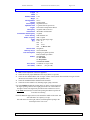
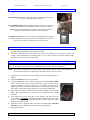
BOOK: Blue Book I SECTION: E-One Teleboom (SGT) Page 1 of 13 E-ONE TELE-BOOM EMERGENCY-ONE CYCLONE ENGINE 50' TELE-BOOM TABLE OF CONTENTS SPECIFICATIONS ............................................................................................................................................ 2 DAILY CHECKS ............................................................................................................................................... 2 SAFETY CHECKS ............................................................................................................................................ 3 START ENGINE ................................................................................................................................................ 3 STOP ENGINE ................................................................................................................................................... 4 EMERGENCY SHUTDOWN PROCEDURE ................................................................................................. 4 ALLISON TRANSMISSION ............................................................................................................................ 4 TELMA RETARDER ........................................................................................................................................ 5 EMERGENCY LIGHTING............................................................................................................................... 5 PUMP OPERATIONS........................................................................................................................................ 5 PUMP ONLY ...................................................................................................................................................... 5 PTO OPERATION ONLY (TELE-BOOM) ..................................................................................................... 5 PUMP AND PTO (TELE-BOOM) OPERATIONS.......................................................................................... 5 THROTTLE ....................................................................................................................................................... 6 SIDE THROTTLE AND REAR THROTTLE ................................................................................................ 6 TELE-BOOM OPERATIONS .......................................................................................................................... 6 DRIVER'S SIDE PUMP PANEL...................................................................................................................... 7 OFFICER'S SIDE PUMP PANEL ................................................................................................................... 7 REAR PANEL .................................................................................................................................................... 7 RELIEF VALVE OPERATIONS ..................................................................................................................... 8 FOAM SYSTEM ................................................................................................................................................ 8 CHECK ENGINE LIGHT ................................................................................................................................ 8 AERIAL OPERATION ..................................................................................................................................... 9 SAFE LOAD AND REACH CHART ............................................................................................................. 10 SITE LOCATION ............................................................................................................................................ 11 PTO OPERATION .......................................................................................................................................... 11 OPEN FLOW SYSTEM .................................................................................................................................. 11 OUTRIGGER OPERATION .......................................................................................................................... 12 UNEVEN TERRAIN ........................................................................................................................................ 12 WINDY CONDITIONS ................................................................................................................................... 12 EXTREME HEAT CONDITIONS ................................................................................................................. 12 FREEZING CONDITIONS ............................................................................................................................ 13 MAIN LEVER CONTROLS ........................................................................................................................... 13 AUXILIARY HYDRAULIC PUMP ............................................................................................................... 13 Format Property of FireNotes, Inc® (OCFD.com) DO NOT DUPLICATE Last Revised: 1/22/2013 3:20:00 PM BOOK: Blue Book I SECTION: E-One Teleboom (SGT) Page 2 of 13 SPECIFICATIONS Length Width Stabilizer Width Height Turning Radius Weight Fuel Capacity Hydraulic Tank Engine Oil Capacity Transmission Transmission Fluid Capacity Power Steering Primer / Capacity Pump Hose Booster Tank Waterway Nozzle Fuel Consumption Ladders Tires (Front) Tires (Rear) 32' 8' 9' 10" 12' 34'-37' 43,000 pounds 50 gallons (diesel) 11 gallons 5W-20 (special oil) 6V92 Turbo 350 hp Detroit Diesel 32 Quarts 30W (motor oil) Allison HT 740 automatic 33 Quarts 10W-40 Motor Oil 30W / 6 quarts Hale 1250 gpm single stage 1100' 4" 200' 2" 300' 1 3/4 " 200' 1" Booster Line 500 gallons 300 to 1000 GPM Pumping 5-6 gallons per hour Road 5-6 Miles per Gallon 50' Tele-boom 10' Attic Ladder 14" Roof Ladder 24' Extension Ladder 315 80R 22.5 (110 psi cold) 12R 22.5 (115 psi cold) DAILY CHECKS 1. 2. 3. 4. 5. Make a visual inspection of the entire apparatus. Check the tires for proper inflation. Front 110 psi, Rear 115 psi cold Check the area underneath the truck for signs of leaks. If noted, check hoses and lines for signs of leaks. (Do not use bare hands to check for hydraulic leaks.) Check the windshield washer fluid and refill if needed. Check all oil and coolant levels, including engine, pump, and axles. Check the radiator through the opening in the top of the cowling forward of the engine opening. There is also a sight glass on the rear of the radiator to the right of center. The engine may shut down if the coolant level is low. CAUTION should always be used when opening the radiator cap after the motor has been running. Check the oil on the right (officer's) side toward the middle of the motor. Fill with 30W motor oil. Capacity is 32 qts. Fill with motor oil on the right (officer's) side through the opening in the forward part of the valve cover. Format Property of FireNotes, Inc® (OCFD.com) DO NOT DUPLICATE Last Revised: 1/22/2013 3:20:00 PM BOOK: Blue Book I SECTION: E-One Teleboom (SGT) Page 3 of 13 DAILY CHECKS - continued Power Steering: The power steering reservoir is on the right side at the rear of the motor. Fill with 10W40 motor oil. The Transmission fill is on the left (driver's) side of the engine at the rear of the motor. Fill with Dextron II transmission fluid. Capacity is 33 quarts. NOTE: Allow the transmission to warm before checking the fluid level. Always check the fluid level while the motor is running The primer reservoir is located on the officer's side behind the access panel to the pump. Capacity is 6 quarts of 30W motor oil. Make sure the top of the reservoir is clean and the ventilation hole in the cap is clear. SAFETY CHECKS 1. 2. Make a check of all lighting including high and low beams, turn signals, hazard flashers, brake, tail, back up lights, and warning lights. Repair any defective lights. Check the windshield wipers, and washer fluid. Check the operation of all instruments, gauges, and controls. After performing the pre-starting checks, you are ready to operate the vehicle. Start the engine and make sure all the systems are functioning. START ENGINE WARNING: All internal combustion engines give off hazardous fumes and gases while running. DO NOT start or run the engine in a closed or poorly ventilated building where the fumes can accumulate. NOTE: The vehicle is equipped with a Neutral Safety Switch that prevents the vehicle from starting in any gear but neutral. IF the vehicle fails to start check the position of the gear selector. 1. 2. 3. 4. 5. 6. 7. Check that the transmission is in (N) neutral and that the parking brake is applied. Turn the MASTER switch to the ON position. Turn the IGNITION switch to the ON position. Push the ENGINE START switch. After the motor starts check the Oil Pressure gauge to make sure the engine has adequate oil pressure (40-60 psi). If necessary run the motor at slightly higher rpm to build up air pressure prior to releasing the parking brake (90-120 psi). Normal operating temperature is 160-210 degrees Fahrenheit. If the engine does not start within 15-20 seconds after cranking, release the start button. Wait approximately 30 seconds and or double-check the starting procedure. If the engine does not start after three of four attempts, stop and refer to the service manual. CAUTION: Repeated or prolonged operation of the starter may result in overheating, damage, or premature wear of starter components, and/or drainage on electrical system. Fasten the seat belt. Apply the brake and release the parking brake (YELLOW BUTTON). Place the Transmission Selector in the desired position. Proceed with caution. Format Property of FireNotes, Inc® (OCFD.com) DO NOT DUPLICATE Last Revised: 1/22/2013 3:20:00 PM BOOK: Blue Book I SECTION: E-One Teleboom (SGT) Page 4 of 13 STOP ENGINE Read the Engine Operating Manual furnished by the manufacturer for recommended procedure. 1. Bring the Engine to a complete stop using the service brake. 2. Shift the transmission to Neutral (N). 3. Set the Parking Brake by pulling the Parking Brake Control (YELLOW BUTTON). 4. Turn off all DOT and warning lights. 5. Allow the engine to idle for 3 to 5 minutes. 6. Push the Engine Stop button until the motor stops completely. 7. Turn off the Ignition Switch. 8. Turn off the Master Switch. CAUTION: Do not turn off the Master Switch until the motor has completely stopped. This may damage the electrical system. EMERGENCY SHUTDOWN PROCEDURE 1. 2. 3. 4. 5. Pull off the road to a safe location. Bring the apparatus to a complete stop. Disengage the transmission and set the parking brake. Flip up the guard marked EMERGENCY SHUTDOWN and flip down the toggle switch. The Emergency Shutdown Switch is located in the bottom right hand side of the MASTER CONTROL PANEL beside the FAST IDLE SWITCH. Notify the shop or Duty Mechanic and Dispatch. ALLISON TRANSMISSION WARNING: Take the following precautions so that unexpected vehicle movement is avoided. Whenever it becomes necessary to leave the vehicle, even momentarily, while the motor is running, place the transmission shift selector in N (NEUTRAL), set the parking brake, and chock the wheels. WARNING: Do not allow the vehicle to coast in N (NEUTRAL). This practice can result in severe transmission damage. Also no engine braking is available when the transmission is in neutral. R Reverse — Completely stop the vehicle before shifting from a forward range to Reverse or from Reverse to a forward range. The selector indicator will display R when in Reverse D Drive — The transmission will initially attain first range when D (Drive) is selected. As vehicle speed increases, the transmission will upshift automatically through the range. As the vehicle slows the transmission will downshift automatically. The SELECT indicator will display the highest range available and the MONITOR will display the current operating range. 3-2 Occasionally road conditions, load, or traffic conditions will make it desirable to restrict automatic shifting to a lower range. Lower ranges provide greater engine braking for going down grades (the lower the range the greater the braking power). Low Range (1) Use this range when pulling through mud and deep snow, when maneuvering in tight places, or when driving down steep grades. First range provides the vehicle with the most driving power and engine braking power. Mode Button: The HT 740 Allison Transmission in the vehicle normally shifts up to fourth gear. This is for Highway Driving. NOTE: For city driving use 3. For highway driving use D. Format Property of FireNotes, Inc® (OCFD.com) DO NOT DUPLICATE Last Revised: 1/22/2013 3:20:00 PM BOOK: Blue Book I SECTION: E-One Teleboom (SGT) Page 5 of 13 TELMA RETARDER The vehicle is equipped with a TELMA retarder. It has four progressive stages of retardation. Four lights mounted on the dashboard indicate how many stages have been activated. An electronic speed switch is used to deactivate the retarder when the vehicle comes to a complete stop. The foot control is adjusted so that the retarder is in position three before the brake is applied. The retarder is capable of supplying up to 85% of the braking requirements. To engage or disengage the retarder push the Retarder Switch (below the Master Warning Switch) at any time. On slick roads lightly pushing the brake pedal will engage only the retarder and not the brakes which will give better control of the vehicle. EMERGENCY LIGHTING The Emergency Lighting controls are located on the console below the door ajar light. The MASTER WARNING SWITCH has to be in the "ON" position before any of the lights will work. The shop advises against leaving the light switches in the "ON" position and just turning the MASTER WARNING SWITCH on and off. This will spike the alternator possible causing damage. PUMP OPERATIONS The following instructions cover both pump and PTO operations. The pump shift on the E-One Tele-Squirt uses a three-position air actuated control. The following steps should be followed to ensure that no damage is done to the transmission or to the pump. NOTE: The throttle will not work if the parking brake is not engaged. PUMP ONLY 1. 2. 3. 4. 5. 6. Shift the transmission to neutral. Shift the pump shift to neutral (middle) position. Wait two to three seconds (count one-one thousand etc.) Move the pump shift to the pump position (bottom). The OK to Pump light will come on. Shift the transmission to Drive (D). The Pump Engaged light will come on. The speedometer will show 25-35 mph. Pump Shift PTO Operation Only (TELE-BOOM) 1. 2. 3. Shift the transmission to (D) Drive. Engage the PTO. Shift the transmission to (N) Neutral. PUMP AND PTO (TELE-BOOM) OPERATIONS 1. 2. 3. 4. 5. Transmission to (D) Drive. Engage the PTO. Shift the transmission to (N) Neutral. Shift the pump shift to the neutral (middle) position. Wait two to three seconds (count one-one thousand etc). PTO Control 6. Move the pump shift to the pump position (bottom). The OK to Pump light will come on. 7. Shift the transmission to Drive (D). The Pump Engaged light will come on. 8. The speedometer will show 25-35 mph. CAUTION: Do not attempt to engage the PTO with the water pump in operation. The water pump must be shut down, and disengaged, before the PTO can be engaged. Severe gear clashing will occur if the transmission is not in the (D) Drive position. Format Property of FireNotes, Inc® (OCFD.com) DO NOT DUPLICATE Last Revised: 1/22/2013 3:20:00 PM BOOK: Blue Book I SECTION: E-One Teleboom (SGT) Page 6 of 13 THROTTLE When you do not have throttle. 1. No throttle in the cab. a. When the pump is in gear. b. When the check engine light is pushed in. 2. No throttle at the pump panel. a. Pump panel throttle will not work when the pump is not engaged. b. When the check engine light is pushed in. 3. Fast idle — 1200 rpm a. Push switch on dashboard. b. Operates only when parking brake is engaged and transmission is in neutral. c. No fast idle when pump is engaged. d. No fast idle when parking brake is released. SIDE THROTTLE AND REAR THROTTLE 1. 2. When changing from the side throttle to the rear throttle. a. Set the proper pump pressure. b. Set the relief valve. c. Throttle down to idle. d. Throw switch to the rear throttle. e. Throttle up with the rear throttle. When changing from the rear throttle to the side throttle. a. Throttle down to idle. b. Throw switch to side throttle. c. Throttle up or shut down as necessary. TELE-BOOM OPERATIONS A. To drain the boom, it must be elevated to the maximum elevation but it is not necessary to extend the boom. B. Do not rest the boom on buildings. C. Pump 180 psi for 1000 gpm. D. Tuck away the nozzle before bedding the boom. E. Retract the boom completely before bedding the boom. F. Do not operate the boom closer than 10 feet from electrical lines. G. If possible do not operate the boom on grades greater than 6%. H. On an incline, operate the boom uphill. The stabilizers will raise and level the rear of the apparatus. Format Property of FireNotes, Inc® (OCFD.com) DO NOT DUPLICATE Last Revised: 1/22/2013 3:20:00 PM BOOK: Blue Book I SECTION: E-One Teleboom (SGT) Page 7 of 13 DRIVER'S SIDE PUMP PANEL All of the controls for all of the discharges are located on the driver's side pump panel. At the top of the panel are the Compound and Pressure Gauge. There are also gauges for RPM, Temperature, and Oil Pressure. Each discharge control has a pressure gauge above it. The discharge controls are arranged in two rows across the panel. TOP ROW LEFT TO RIGHT: Tank Fill Foam Water Hosereel (Boosterline) Front Jumpline Rapid Deployment Waterway 1 1/2" Rear Discharge BOTTOM ROW LEFT TO RIGHT: 3" Large Diameter Discharge (Stortz Connection) Discharge 1 Discharge 2 Discharge 3 Discharge 4 The Tank to Pump valve is located just below Discharge 4. The Throttle, Primer, Auxiliary Cooling, and Pump Drain are on the left side of the panel. Along the bottom right side left to right are the drains for: Hosereel Front Jumpline Rapid Deploy 1 1/2” Left Rear The Relief Valve and Foam Controls are also located on this panel. They will be covered later. OFFICER'S SIDE PUMP PANEL All of the controls for the discharges are located on the Driver's side pump panel. The only controls on the Officer's side are for the Intakes and Drains. The discharges are along the top row. They are from left to right: Discharge 4 Discharge 3 Discharge 2 Discharge 1 3" Discharge (Stortz Connection) The Intakes are as follows: 5" Steamer Connection in the middle of the panel Two Pony Suctions with 4" Stortz Connections are located to either side and slightly below the Steamer Connection. The drains for the connections are as follows: Discharge 3, Discharge 1, and both suctions are located below the connections. Waterway, Discharge 4, Discharge 2, and the 3" Discharge are along the bottom of the panel. REAR PANEL All of the controls for the Tele-Boom are located on the Rear Panel at the top. On the Switch Panel are controls for Power, Nozzle, and Jacks. The levers to the right of the Switch Panel control the operation of the boom. They are left to right: Up-Down, Right-Left, Extend-Retract There are also controls at the tip of the ladder for the control of the nozzle. To change power from the Jacks to push-pull knob located below the spe panel is a 4" Stortz connection that ma intake. This is controlled by the W connection and on the Driver's Pump P for the Waterway. Format Property of FireNotes, Inc® (OCFD.com) DO NOT DUPLICATE Last Revised: 1/22/2013 3:20:00 PM BOOK: Blue Book I SECTION: E-One Teleboom (SGT) Page 8 of 13 RELIEF VALVE OPERATIONS The Relief Valve is located on the upper left side of the Driver's side Pump Panel. To set the relief valve follow these steps. 1. With the throttle, adjust the pump discharge pressure to 5 psi above the desired pressure. 2. Turn the relief valve wheel counter clockwise until the pressure drops. The light should come on at this time. 3. Turn the relief valve wheel clock wise until the pressure is 5 psi above the desired Pump discharge pressure. 4. With the throttle, lower the pressure to the desired psi. 5. The relief valve is now set. FOAM SYSTEM All of the controls for the Foam System are located on the Driver's Side Pump Panel. A. Operation of the foam system. 1. Open the Water Valve. 2. Determine the gpm flow and set the metering valve. 3. If operating from a hydrant, gate down the intake to 10 psi or less. 4. Open the foam valve. 5. Engine pressure must be at least 125 psi. NOTE: The pump operator must be alert to the shutting on and off of the nozzle and open and close the foam valve each time. B. Shutdown of the foam system. 1. Close the foam valve. 2. Close the eductor valve. C. Flushing the Pump. 3. Hook-up to a hydrant. 4. Flush each discharge on the pump even if they were not used. 5. Be careful not to allow foam to enter the booster tank. a. Keep the Tank valve closed. b. Keep the Tank to Pump valve closed. REMEMBER: 1. The metering valve must be reset each time the gpm flow rate is changed. 2. The suction pressure must not exceed 10 psi. 3. The engine pressure must be at least 125 psi. 4. The engine pressure must not exceed 250 psi. CHECK ENGINE LIGHT The Check Engine Light is located on the Master Panel between the Fast Idle Switch and the Retarder Switch. When the Check Engine Light is pushed in two things will happen. First, the foot throttle is disengaged. Second, the light will flash a code. Count the light flashes. 2 then 5 flashes means that everything is in good working order. Any other code means there is something wrong with the apparatus. Report any other code other than 2 — 5 to the maintenance shop. REFER TO THE FOLLOWING SECTION, AERIAL OPERATION, FOR LOAD INFORMATION AND OPERATION OF THE TELE-BOOM. Format Property of FireNotes, Inc® (OCFD.com) DO NOT DUPLICATE Last Revised: 1/22/2013 3:20:00 PM BOOK: Blue Book I SECTION: E-One Teleboom (SGT) Page 9 of 13 SECTION 12 AERIAL OPERATION INTRODUCTION The simplicity of the contemporary, well designed hydraulic system and telescoping boom assembly allow for an individual with average ability and proper training to become proficient in operating the 50’ Telescoping Boom. The safe and efficient execution of telescoping boom assembly functions during operations will depend, in part, on the operator’s capacity not to exceed the limitations and safety factors of the boom design. Well trained operators should be the only personnel allowed to operate the boom assembly, observing the following rules to ensure safety and efficiency: WARNING: 1. 2. The boom and ladder assembly is not insulated. Keep the telescoping boom and ladder at least 10 feet from overhead power lines. When elevating the boom and ladder near power lines, personnel on the ground should stand clear of the vehicle, and avoid stepping onto or touching the vehicle until the boom and ladder are in a safe position with respect to the overhead power lines. Personnel touching the ground and the vehicle, with the boom and ladder contacting an energized power line, will become a pathway to ground for electrical current, resulting in severe injury. Complete a comprehensive study of the manual and have a thorough knowledge of operating instructions, safety precautions, unit capabilities, and limitation. Learn to operate the controls without looking at the control panel. Learn the location of each control, its function, and how it operates. WARNING: The operator should never leave the rear boom control station during on-scene operations. If personnel on the boom assembly become overcome by smoke, or otherwise incapacitated, the operator at the rear station can move the boom assembly to safety. 3. Operate the controls smoothly to prevent jerking and erratic boom movement. Whipping and bouncing are the most likely cause of damage to the boom, ladder, and rotation gear assemblies. 4. Practice basic no-load operations at low engine RPM setting under capable supervision during training. 5. Practice full-load operations in simulated “on the scene” conditions. 6. Do not leave the operators control station with the boom assembly raised, or in an operational capability. 7. Do not lower the boom assembly on buildings, trees, telephone poles, lights, or the truck body. 8. Give undivided attention to the boom and ladder assembly during operations; if distracted, stop operation. 9. The operator should keep his eyes on the telescoping boom assembly to avoid overhead electrical wires or any object which could be struck. 10. Make a visual inspection of the unit before operating. Perform inspection of the boom assembly and outriggers daily. Perform daily operational tests to ensure unit readiness. 11. Note and report any signs of trouble during operation, paying particular attention to the following: a) Drifting hydraulic cylinders. b) Excessive oil pressure, oil leaks, and excessive oil consumption. c) Unusual noises or vibration in the hydraulic pump. d) Erratic movement of boom assembly, turntable, outrigger jacks, or function controls. e) Metal particles, sand, or other contamination on boom assembly extension slide surfaces, waterway pipes, outrigger jack legs, or cylinder rod slide surfaces. f) Unlubricated boom extension slide pads, waterway pipes, or outrigger jack leg slide surfaces, cables, pulleys, and pin retainers. g) Loose or missing retainer clips, pins, snap rings, bolts, and screws. Format Property of FireNotes, Inc® (OCFD.com) DO NOT DUPLICATE Last Revised: 1/22/2013 3:20:00 PM BOOK: Blue Book I SECTION: E-One Teleboom (SGT) Page 10 of 13 Figure 12-1. SAFE LOAD AND REACH CHART Distribution on 1,000 GPM** Horizontal Reach to Working Height Boom* Water Flow Running Board Above Ground BOOM @ 80-DEGREE ELEVATION – FULL EXTENSION 400 LB. 0 YES 4 feet 50 feet 200 LB. 600 LB. YES 4 feet 50 feet 800 LB. 0 NO 4 feet 50 feet 200 LB. 1,400 LB. NO 4 feet 50 feet BOOM @ 45-DEGREE ELEVATION – FULL EXTENSION 400 LB. 0 YES 28 feet 42 feet 200 LB. 600 LB. YES 28 feet 42 feet 800 LB. 0 NO 28 feet 42 feet 200 LB. 1,400 LB. NO 28 feet 42 feet BOOM @ 0-DEGREE ELEVATION – FULL EXTENSION 0 0 YES 42 feet 11 feet 500 LB. 0 NO 42 feet 11 feet 200 LB. 800 LB. NO 42 feet 11 feet * Distributed weight is to be equally distributed over the entire length of the boom ladder assembly. ** Water flow is 1,000 GPM maximum. Table 12-1. SAFE LOAD AND REACH CHART Tip Load Format Property of FireNotes, Inc® (OCFD.com) DO NOT DUPLICATE Last Revised: 1/22/2013 3:20:00 PM BOOK: Blue Book I SECTION: E-One Teleboom (SGT) Page 11 of 13 SITE LOCATION The vehicle should be positioned at a location where the ground is stable and the vehicle will be as level as possible. Maximum outrigger jack loads are generated during operation of the boom assembly at full extension and low elevation to the side of the vehicle. Use good judgment in a potentially precarious situation to not jeopardize vehicle stability. Take into consideration the following conditions: 1. Overhead power lines within 10 feet of the boom assembly extension or other obstructions. The boom assembly is not insulated and becomes a direct line for electrical flow. 2. Reach capability of the boom assembly to required area. 3. Hot and/or soft asphalt where outrigger jack pads may sink or shift and cause the vehicle to become unstable. 4. Soft earth or ground erosion from rain or pump runoff water. 5. Frozen ground thaw from vehicle-created heat. 6. Retaining wall heights, open construction areas, and underground parking ramps and garages. 7. Outriggers should not bridge curbs, ditches, ramps, or run-off drains, or be placed over manhole covers or sewer pipes. 8. Uneven terrain or sloped surfaces. Use wheel chocks under the wheels. PTO OPERATION The power required to drive the main hydraulic pump is supplied by a vehicle engine/transmission driven Power Take Off (PTO) unit. The PTO control is located on the center control console panel in the vehicle cab. Outrigger and boom assembly operations can begin after the PTO is engaged. Engage the PTO in accordance with the following instructions: CAUTION: Do not attempt to engage the PTO while the water pump is in operation. Shut the water pump down, then engage the PTO. Do not attempt to engage the PTO with the transmission in Neutral, or severe gear clashing will occur. 1. 2. 3. 4. 5. 6. Ensure the battery selector switch, located in the vehicle cab, is in the BOTH position. Ensure the vehicle engine is running. Set the parking brake. Place the transmission in Drive. Place the PTO switch to IN, engaging the PTO. Place the transmission in Neutral (N). The red PTO indicator lamp will light. NOTE: On vehicles with an air-pressure activated PTO, the air pressure required for PTO engagement is 70-140 PSI. Observe the pressure gauge on the instrument panel. On vehicles with an electro-hydraulic activated PTO, the PTO may be engaged in any gear, provided the engine RPM is set at low idle RPM. CAUTION: Always disengage the PTO after use. The hydraulic pump, PTO or transmission may be damaged if the vehicle is driven any distance with the PTO engaged. OPEN FLOW SYSTEM With the engine at governed RPM, the hydraulic pump supplies fluid to the inlet ports of the various system control valves. The hydraulic fluid circulates through the controls valves, filters, etc., and returns to the supply reservoir if the operating controls remain in neutral. Pressure in this non-functioning condition is very slight since minimal resistance is encountered. When the operator actuates a control lever, pressure in the applicable line of the selected system increases simultaneously, resulting in the functional performance of the selected system. Format Property of FireNotes, Inc® (OCFD.com) DO NOT DUPLICATE Last Revised: 1/22/2013 3:20:00 PM BOOK: Blue Book I SECTION: E-One Teleboom (SGT) Page 12 of 13 OUTRIGGER OPERATION The purpose of the outrigger system is to relieve the vehicle sprung suspension weight, and to provide an expanded level, rigid base for boom operations. Field circumstances can present less than ideal conditions for maximum stability provided by the outriggers. Keep in mind that the more out-of-level the vehicle is, the more boom assembly stability is reduced. Extend outrigger jacks in accordance with the following instructions. The engine RPM are automatically increased with outrigger operation. 1. Position the vehicle at the selected site. 2. Set the parking brake, and wedge-block both the front and rear wheels. 3. Engage the PTO. 4. Position the MASTER POWER switch to ON. The MASTER POWER indicator lamp will light. Position the BOOM/JACKS transfer switch to JACKS. 5. Spot the auxiliary jack pads. Using the JACKS switches on the control panel, lower the outrigger jack until the jacks stop in the fully extended position. 6. Position the BOOM/JACKS transfer valve to BOOM. 7. Visually check the outriggers for stable position. 8. Block the wheels after the outrigger jacks are set. NOTE: The auxiliary jack pads are located on the underside of the vehicle body, adjacent to each jack. The pads are intended to be used whenever the jacks are operated. NOTE: Remove the wheel wedge-blocks before lowering the vehicle, and stowing the outrigger jacks. UNEVEN TERRAIN NOTE: The first choice when encountering uneven terrain is to relocate the vehicle. If on-scene emergency conditions do not permit relocation, blocking may have to be used. Blocking may be used on a vehicle when uneven terrain prevents an outrigger from being lowered enough to give proper stability. Caution should be exercised when using blocking. Place the blocking so it will not slip from under the jack pad. NOTE: Emergency One does not recommend that blocking be used, but recognizes that not all emergency situations will allow ideal operating conditions. WINDY CONDITIONS Telescoping boom assembly operations are not recommended with wind speeds in excess of 35 MPH. Operations with full load and extension are capable of being performed by the boom assembly within the 35 MPH wind speed limit. EXTREME HEAT CONDITIONS If the boom or ladder assembly is exposed to extreme heat during operation, thoroughly inspect the boom and ladder, directing particular attention to the boom extension slide pads, cables, waterway seals, and hydraulic lines. The boom and ladder should be inspected and tested in accordance with NFPA 1904 standard testing. If the temperature indicator decal at the boom tip indicates extreme heat exposure, test the boom material for structural hardness. Format Property of FireNotes, Inc® (OCFD.com) DO NOT DUPLICATE Last Revised: 1/22/2013 3:20:00 PM BOOK: Blue Book I SECTION: E-One Teleboom (SGT) Page 13 of 13 FREEZING CONDITIONS A substantial build-up of ice is very probable in freezing weather when operating a waterway system on the telescoping boom assembly. NOTE: Do not allow ice to build up on the boom, ladder, or prepiped waterway tubes. Ice build up and accumulation on the ladder will decrease load and extension capability. Use a steam cleaner, hot water, or de-icer to remove ice. Do not chip ice with an axe. Boom and ladder movement should be possible even with a build up of ice. Ice build up on the boom and ladder may have to be tolerated until corrective action can be taken. Avoid ice accumulation on any controls. NOTE: Hydraulic boom and ladder movement will be comparatively slow when the fluid is cold. Normal operating speed will return as the fluid warms from circulation. When a vehicle has been exposed to below zero weather without operating for a prolonged period of time, allow the fluid to circulate at low throttle until the fluid becomes warm before operating the boom and ladder or outrigger functions. Oil locked in the outrigger cylinders, or any cylinder for an extended period of time during operating, will quickly return to ambient temperature. Thoroughly inspect the boom and ladder assembly after operating in ice and freezing conditions. Particular attention should be directed to the extension slide pads, cables, pulleys, and hydraulic lines. Ensure waterway pipes have been drained. MAIN LEVER CONTROLS The operator control panel is located at the rear/center of the vehicle, and has 3 levers, controlling 3 ladder functions of raising/lowering, extending/retracting, and rotation. An optional set of controls may be located at the pump panel operator’s station. Apply slow even pressure to control levers for smooth boom function starts and stops. Hold each lever up or down until the desired boom position is obtained. Increasing the operational speed of a function is controlled by lever movement away from its neutral position. Use the finger and hand rests (formed ring around control levers), for improved hand stability and metering control. CAUTION: Always operate controls slowly and smoothly to avoid jerky and erratic boom movement. Do not make sudden control lever engage or disengage movements. Sudden erratic or jerking motion could endanger personnel, and cause damage to the boom and ladder assembly. AUXILIARY HYDRAULIC PUMP The boom assembly and outriggers may be moved to the stowed position in case the main hydraulic pump malfunctions or the vehicle engine stalls, using the auxiliary hydraulic motor/pump. The auxiliary hydraulic motor/pump is driven by a 12 volt DC electric motor which uses the vehicle batteries as a power source. Use of the auxiliary pumps will enable operation of all hydraulic functions, but not simultaneous operation. The operational speed of each function will be reduced dir to a substantially lower GPM flow than the main hydraulic pump. CAUTION: The auxiliary motor/pump is not designed or intended for continuous use. Operation should be limited to the required time to return the boom and outriggers to the stowed position. Activate the auxiliary pumps by holding the momentary contact switch to ON, while simultaneously operating the retract, rotate, and lower control levers. After operations have been completed, release the momentary contact switch to halt auxiliary pump operation. NOTE: A momentary contact switch to activate the auxiliary pump is located at the rear operator control station for boom and outrigger operation. Optional switches may be located at the pump operator’s station. Format Property of FireNotes, Inc® (OCFD.com) DO NOT DUPLICATE Last Revised: 1/22/2013 3:20:00 PM