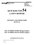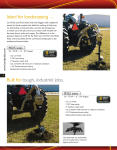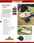
1
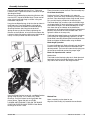
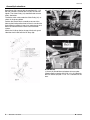
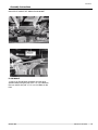
Snow Plow
Assembly Instructions
Manual No. 701-157M
Treker NT & ST Series
Before You Start
!
When you see this symbol, the subsequent
instructions and warnings are serious - follow
without exception. Your life and the lives of
others depend on it!
!
DANGER
Exercise EXTREME CAUTION when plowing. Always plow at
a slow speed.
!
WARNING
TO AVOID SERIOUS INJURY OR DEATH:
IMPORTANT: Before you begin, read these
instructions and check to be sure all parts and tools
are accounted for. Please retain these installation
instructions for future reference and parts ordering
information.
Your Snow Plow is exclusively designed for your Land
Pride NT & ST Treker. Please read these installation
instructions and your NT & ST Treker Operator’s Manual
thoroughly before beginning. Especially read information
relating to safety concerns. Also included in the
Operator’s Manual is important information on operation,
adjustment, troubleshooting, and maintenance for this
attachment (some manual sections do not apply to all
accessories).
General Information
These assembly instructions apply to the following Snow
Plow Accessories listed below:
701-067A
701-068A
NT 60" SNOW PLOW
ST 60" SNOW PLOW
Further Assistance
Your dealer wants you to be satisfied with your new
Snow Plow. If for any reason you do not understand any
part of this manual or are not satisfied with the service
received, the following actions are suggested:
1. Discuss the matter with your dealership service
manager making sure he is aware of any problems
you may have and that he has had the opportunity to
assist you.
2. If you are still not satisfied, seek out the owner or
general manager of the dealership, explain the
problem and request assistance.
3. For further assistance write to:
Land Pride Service Department
1525 East North Street
P.O. Box 5060
Salina, Ks. 67402-5060
E-mail address
[email protected]
© Copyright 2007
Printed
06/26/07
1.
2.
DO NOT EXCEED 5 MPH WITH BLADE INSTALLED.
OPERATE WITH EXTREME CAUTION ON SLOPES,
STEEP GRADES, AND ROUGH TERRAIN.
KEEP AWAY FROM BLADE AND MOVING PARTS
DURING OPERATION.
WHEN PLOWING SNOW OR DIRT INTO A PILE, START
BACKING UP BEFORE RAISING THE BLADE.
DO NOT RAM THE BLADE INTO THE PILE. ** SLOW
DOWN BEFORE HITTING PILE. **
BE AWARE OF POSSIBLE HIDDEN OBJECTS UNDER
SNOW.
3.
4.
5.
6.
!
CAUTION
TO AVOID PERSONAL OR OTHER INJURY:
1.
READ BLADE OWNER?S MANUAL, ATV OPERATOR?S
MANUAL, AND SAFETY DECALS BEFORE OPERATING.
2. WEAR HEAD PROTECTION, SAFETY GLASSES, AND
SHOES AS RECOMMENDED IN ATV OPERATOR?S
MANUAL.
3. ALLOW NO RIDERS ON BLADE OR ATV WHILE
MOVING OR STATIONARY.
4. KEEP BYSTANDERS AWAY FROM BLADE OR ATV
WHILE MOVING OR STATIONARY.
5. BEFORE ADJUSTING BLADE ANGLE STOP ATV
ENGINE, SET AND LOCK BRAKES, RAISE AND LOCK
BLADE IN UP POSITION. DO NOT ATTEMPT TO RAISE
BLADE BY HAND; USE THE LIFT HANDLE ONLY.
6. BEFORE ADJUSTING BLADE HEIGHT: LOWER
BLADE TO THE DOWN POSITION.
7. WHEN BLADE IS NOT IN USE, STOP ATV ENGINE, SET
AND LOCK BRAKES, AND LOWER BLADE TO DOWN
POSITION.
! ! ! OPERATION ! ! !
Your blade and hardware were designed with your safety
in mind. In order to protect you and your machine, certain
parts of the blade and / or hardware are designed to fail
when the equipment is over stressed. For this reason
Push Tubes, Blade Hinges, Foot Peg Brackets, Push
Plate Attaching Pins and Clevis Pins are not covered by
Warranty.
Blade angle is adjustable. Lock blade in the up position.
To move the blade left, right or straight, pull the Blade
1
Land Pride
Assembly Instructions
Position Lever ahead and turn the blade to the desired
position. The Lever will spring back when the blade is at
the correct angle.
The blade skids are adjustable so the blade can be
lowered but still held a certain distance off the ground.
The blade is designed to trip when it strikes an object or
digs in too far. When pressure is released the blade
springs back into position. Blade spring tension may be
set stiffer by tightening the Locknuts on the bottom of the
Eyebolts. For less spring tension, loosen the Locknuts.
Do not exceed 5 MPH with blade installed.
Operate with extreme caution on slopes, steep grades
and rough terrain.
Keep away from blade and moving parts during
operation.
When plowing snow or dirt into a pile, start backing up
before raising the blade.
Do not ram the blade into the pile ** SLOW DOWN
BEFORE HITTING THE PILE. **
Be aware of possible hidden objects under snow.
Wear head protection, safety glasses and shoes as
recommended in the machine’s Operator’s Manual.
Allow no riders on blade or machine while moving or
stationary.
Keep bystanders away from blade and machine while
moving or stationary.
When blade is not in use, stop the machine?s engine, set
and lock brakes, and lower blade to down position.
Only mature adults over the age of 16 should operate the
machinery. Do not operate this machinery if you are
under the age of 16.
Assembly Instructions
A detailed listing of parts for this accessory kit is provided
on page 6. Use the list as a checklist to inventory parts
received. Please contact your local Land Pride dealer for
any missing hardware.
UNIVERSAL PUSH TUBE Part No. 823-226C
!
WARNING
! Due to reduced ground clearance remove plow Mount
Brackets before trail riding.
! Do not exceed 5 MPH with the blade or its brackets installed
OPERATION TIPS
! When plowing snow or dirt into a pile, back away from
the pile before attempting to raise the blade
! For best results set the suspension to the stiffest setting
if possible
! The Blade is shipped with the Blade Skids mounted
upside down for boxing. Be sure to mount the Skids
properly before using your blade.
MAINTENANCE
! Periodically check for wear and tightness of all bolts,
nuts and fasteners. Replace or tighten as necessary.
Grease all pivot points and hinges as needed
NOTICE
! The use of Winch Mounting Kits Not Manufactured by
Land Pride Accessories with Work Power Blades will
void all warranties.
! The Winch Kits are specifically designed to help prevent
damage to the Blades, Winch Kits and the Machine.
Please read and follow all of the instructions in the
owner?s manual.
All directions referring to the right and the left are when
the operator is sitting on the machine.
Please read and follow all of the instructions in the
machine’s operations manual.
Blade Connection
Keep all bystanders a minimum of 15 Meters away from
the machine and Blade when it is in operation.
To secure the Blade to the Blade Hinge (#2), Place the
Steel Bushings (#9) into the holes in the Blade Hinge
(#2), Using the Top holes in the Blade, Secure the Blade
Do not use this equipment at night (in the dark) or under
poor weather conditions, unless your machine has
adequate lighting, which produces clear safe vision.
Due to the extra length of the 60" (1.52 M) Blade, loss of
directional control may result when pushing heavy
material. Use with Caution!
2
Manual No. 701-157M
■
06/26/07
Land Pride
Assembly Instructions
Hinge (#2) to the Blade with the 1/2" x 1 " Bolts and
Locknuts (#15). Tighten Nuts to 60 Ft Pounds of Torque.
See diagram below.
Remove the two Blade Spring Attaching Brackets (#8)
from the LEFT side of the Blade Hinge. Fasten one on
either side of the Blade Hinge as shown in the parts
breakdown and picture.
Hang the two Blade Springs (#16) from the top holes in
the Blades ribs. Place the Eyebolts (#14) onto the
springs and fasten the Eyebolts to the Blade Spring
Attaching Brackets (#8) using the two locknuts.
Spring tension may be set stiffer by tightening the
locknuts on the Eyebolts, or for less tension loosen the
Locknuts. Setting the tension stiffer means the blade will
not trip as easily as when set with less tension.
These Instructions are for the Push Tube Assembly only.
Final Blade Installation
Position the Push Tube Assembly (#1) under the
machine. Lift the rear of the assembly up and secure it to
the Push Tube Attaching Brackets using the 3/8" Clevis
Pins and #3 Hairpins provided in the Attaching Kit.
The Blade Stops (#4) on either side of the Blade Hinge
are shipped loose. By turning the Stops around, the pitch
of the Blade changes. The recommended pitch is one
that allows the top and bottom of the blade to be
perpendicular to the ground. Set the Stops to the desired
position, they must be the same on both sides, and
tighten the bolts on the stops fully.
The Blade Skids on 60" blades are installed up side down
at the factory for shipping/boxing purposes. Turn the
Blade Skids around by loosening the two end bolts on the
Blade and tighten the Bolts before using the Blade.
Blade Angle Operation
To move the Blade Left, Right or Straight, pull the Blade
Position Lever (#5) forward and turn the blade to the
desired position. The Lever will automatically spring into
the slot when the Blade reaches the proper angle.
Blade Lift Operation with a winch
Method One:
The blade can be lifted using the winch. Hook the winch
hook onto the slot in the Blade Position Lever Bracke
(#3) and lift with the winch. See diagram below.
Install the Blade Position Lever (#5), and Blade Position
Spring using the 5/16" x 2 1/4" Bolt (#12), Roller
Bushings, and 5/16" Nylock Locknut provided. See
picture above. Tighten bolt fully and THEN
LOOSEN JUST ENOUGH TO ALLOW THE BLADE
POSITION LEVER TO MOVE FREELY. Both Roller
Bushings on the LEFT side.
06/26/07 ■
Method Two:
Some assembly may be done for you.
Align the Cable Pulley (#1) between the two Snatch
Manual No. 701-157M
3
Land Pride
Assembly Instructions
Block Straps (#2), secure with the supplied 1/2"x 1 1/2
bolt (#3) and the 1/2"center lock nut (#4). Do not over
tighten. The Cable Pulley (#1) should be able to move
freely. See below.
823-230C ST MOUNT KIT-SNOW PLOW W/INST
Thread the winch cable under the Cable Pulley (#1) as
shown in the picture below.
Position the Snatch Block assembly over one of the
holes on the blade position lever bracket. Insure that the
Snatch Block assembly is free of any moving parts and
does not interfere with the normal use of the blade
system.
Attach the Lift Strap (#6) to the top of the brush guard.
Hook the winch hook onto the Lift Strap (#6).
PLOW MOUNT
1. Attach (#1) Blade Mount to bottom of frame tubes
(Shown above) using the (#5) 5/16" x 2" x 3" U-Bolts for
the rear and the (#4) 3/8" x 1 1/2" x 2 1/2"U-Bolts for the
front.
4
Manual No. 701-157M
■
06/26/07
Land Pride
Assembly Instructions
823-227C NT MOUNT KIT-SNOW PLOW W/INST
PLOW MOUNT
1. Attach (#1) Blade Mount to bottom of frame tubes
(Shown above) using the (#5) 5/16’" x 2" x 3" U-Bolts for
the rear and the (#4) 3/8" x 1 1/2"x 2 1/2U-Bolts for the
front.
06/26/07 ■
Manual No. 701-157M
5
Land Pride
Listing of Parts
Kit No. 823-224C
6
60" STEEL SNOW PLOW
Item
Part No.
Part Description
1
2
2
3
4
5
5
6
7
823-224C
802-282C
803-084C
PUR0400
805-240C
CYC0790
PUR1494
804-021C
PUR1467
60" STEEL SNOW PLOW
RHSNB 5/16-18X1 GR5
NUT HEX NYLOCK 5/16-18 PLT
5/8" X 1" SPACER
PIN LINCH 3/16 X 1 9/16 LONG
60" WEAR BAR METAL (Optional)
60" WEAR BAR PLASTIC (Optional)
WASHER FLAT 5/8 SAE PLT
H. D. SKID
Qty
1
9
9
4
2
1
1
12
2
Manual No. 701-157M
■
06/26/07
Land Pride
Assembly Instructions
Kit No. 823-226C
Item
1
2
3
4
5
6
7
8
9
10
11
12
13
14
15
16
17
18
19
06/26/07
PUSH ARMS FOR SNOW PLOW
Part No.
Part Description
823-226C
CYC3154
CYC2389
CYC0345
CYC0813
CYC2259
PUR1437
PUR1361
CYC0812
PUR1411
802-079C
803-155C
802-138C
802-159C
PUR1216
802-091C
803-019C
PUR1409
U610
PUSH ARMS FOR SNOW PLOW
Y2K PUSH TUBE
BLADE HINGE
BLADE POSITION LEVER BRACKET
ADJUSTABLE BLADE STOPS
BLADE POSITION LEVER
SPRING
SLEEVE BUSHING
BLADE SPRING BRACKETS
7/8" STEEL BUSHING
HHCS 3/8-16X1 1/4 GR5
NUT LT JAM 1 1/4-12 NYLN INSRT
HHCS 5/16-18X2 1/4 GR5
HHCS 5/16-18X1 GR5
5/16" X 4-1/4" EYE BOLT
HHCS 1/2-13X1 1/2 GR5
NUT LOCK 1/2-13 PLT
BLADE SPRING
1 3/8" END CAP
SNATCH BLOCK ASSEMBLY
Qty
1
1
1
2
1
1
2
2
2
2
1
1
2
2
2
2
2
2
1
■
Manual No. 701-157M
7
Land Pride
Assembly Instructions
Kit No. 823-230C
8
ST MOUNT KIT-SNOW PLOW
Item
Part No.
Part Description
1
2
3
4
5
6
7
CYC4610
PUR1209
805-010C
PUR1415
PUR1435
804-011C
804-010C
803-078C
803-084C
BLADE MOUNT
3/8" CLEVIS PIN
PIN HAIR COTTER .094
3/8" X 1-1/2" X 2-1/2" U-BOLT
5/16" X 2" X 3 U-BOLT
WASHER FLAT 3/8 USS PLT
WASHER FLAT 5/16 USS PLT
NUT LOCK 3/8-16 NYLON INSERT
NUT HEX NYLOCK 5/16-18 PL
■ 701-157M
Manual No.
Qty
06/26/07
Land Pride
Assembly Instructions
Kit No. 823-227C
NT MOUNT KIT-SNOW PLOW
Item
Part No.
Part Description
1
2
3
4
5
6
7
CYC4598
PUR1209
805-010c
PUR1415
PUR1435
804-011C
804-078C
803-078C
803-094C
BLADE MOUNT
3/8" CLEVIS PIN
RPBY 805-010C
3/8" X 1-1/2" X 2-1/2" U-BOLT
5/16" X 2" X 3 U-BOLT
WASHER FLAT 3/8 USS PLT
WASHER INTERNAL STAR 3/8 PLT.
NUT LOCK 3/8-16 NYLON INSERT
NUT 5/8-11 NYLON COLLAR THIN
06/26/07
Qty
■
Manual No. 701-157M
9
Corporate Office: P.O. Box 5060
Salina, Kansas 67402-5060 USA
www.landpride.com