1
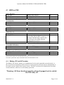
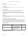
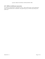
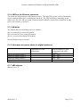
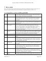
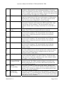
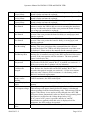
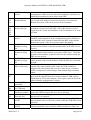
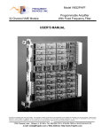
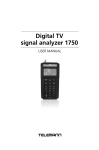
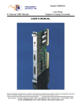
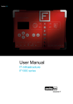
Operators Manual
For DM300 S-VDR and DM500 VDR
Document Number 9200328
Version Number
1.2
Date
March 2007
Operators Manual for DM300 S-VDR and DM500 VDR
Revision record
Version
1.0
1.2
Date
September 2006
March 2007
9200328 V1.2
Description
Original issue of document
Minor errors corrected
Page 2/24
Operators Manual for DM300 S-VDR and DM500 VDR
Contents
REVISION RECORD ...........................................................................................................2
1
1.1
1.2
2
SCOPE AND PURPOSE ..........................................................................................5
References................................................................................................................5
Terms and Abbreviations ..........................................................................................5
SYSTEM OVERVIEW ...............................................................................................6
2.1.1
Data Acquisition Unit..........................................................................................6
2.1.2
Bridge Alarm Unit (BAU) ....................................................................................6
2.1.3
Bridge Microphone Units....................................................................................7
2.1.4
Data Capsule .....................................................................................................7
2.1.5
Sensor Interface Unit (SIU) ................................................................................7
2.1.6
Remote video interface (RVI).............................................................................7
3
OPERATION.............................................................................................................8
3.1
Bridge alarm Unit ......................................................................................................8
3.1.1
Alarm display .....................................................................................................8
3.1.2
Means for initiating a backup .............................................................................8
4
OPERATION DAU ..................................................................................................10
4.1
LEDS on PSU .........................................................................................................11
4.1.1
Battery, DC and AC breaker ............................................................................11
4.1.2
AC inlet ............................................................................................................12
4.1.3
DC inlet ............................................................................................................12
4.1.4
DC to DPU .......................................................................................................12
4.2
DPU ........................................................................................................................12
4.2.1
VDR status display and VDR status LED.........................................................12
4.2.2
VDR status display Error codes .......................................................................12
4.2.3
LEDs in the Ethernet connectors .....................................................................13
5
OPERATION OF SIU..............................................................................................14
5.1
LEDs on Module Rack ............................................................................................14
5.1.1
AC LED ............................................................................................................14
5.1.2
Link indications ................................................................................................14
5.1.3
AC beaker ........................................................................................................14
5.1.4
LEDs in the Ethernet connector .......................................................................15
5.1.5
Modules ...........................................................................................................15
5.1.6
Allocation of system labels for digital interfaces...............................................15
5.1.7
MR address......................................................................................................15
6
OPERATION OF RVI..............................................................................................16
6.1.1
RVI address .....................................................................................................16
6.1.2
Ethernet ports ..................................................................................................16
9200328 V1.2
Page 3/24
Operators Manual for DM300 S-VDR and DM500 VDR
6.1.3
ST LED ............................................................................................................16
7
7.1
7.2
ERROR CODES .....................................................................................................17
General Error code for S-VDR and G2VDR ............................................................17
Additional Error codes for G2VDR installations.......................................................22
8
8.1
SERVICE AND MAINTENANCE ............................................................................23
List of spare parts....................................................................................................23
9200328 V1.2
Page 4/24
Operators Manual for DM300 S-VDR and DM500 VDR
1 Scope and purpose
Operators Manual for DM300 S-VDR and DM500 VDR
1.1 References
9200238
9200327
9200328
9200331
9200343
Installation manual for DM300 S-VDR and DM500 VDR
Installation manual for DM500 VDR Sensor Interface Unit
Operators Manual for DM300 S-VDR and DM500 VDR
Installation manual for DM300 and DM500 Remote Video Interface
Inspectors and Authorities Manual for DM300 S-VDR and DM500 VDR
1.2 Terms and Abbreviations
BAU
BMU
DAU
DPU
SIU
RVI
Bridge Alarm Unit
Bridge Microphone Unit
Data Acquisition Unit
Data Processing Unit (located inside the DAU)
Sensor interface unit
Remote Video Interface
9200328 V1.2
Page 5/24
Operators Manual for DM300 S-VDR and DM500 VDR
2 System overview
System overview for DM300 S-VDR and DM500 G2VDR:
BAU
DAU
RS-422
Power
Firewire
STP CAT5
BMU
BMU
BMU
BMU
BMU
BMU
Capsule
Ethernet STP CAT5
VDR: 6 x BMU
S-VDR: 4 (6) x BMU
1 (5) additional
audio channels for
VHF or BMUs
1 x VHF 8 x Serial 2 x Radar
e.g. GPS
RVI
Optional
P/N 1000723
Ethernet STP CAT5
SIU
Not applicable for S-VDR
(2) x Radar
Number in parenthesis denotes
optionally equipment is needed
8 x Serial 8 (16) Analog 48 (64) Digital
System overview
2.1.1 Data Acquisition Unit
The Data Acquisition Unit contains the Data Processor Unit (DPU) and the Power Supply Unit
(PSU). The DAU must be installed indoors near the bridge.
2.1.2 Bridge Alarm Unit (BAU)
The BAU must be installed on the bridge either in a console or mounted on a bulkhead. System
errors will generate a visual and audible alarm.
9200328 V1.2
Page 6/24
Operators Manual for DM300 S-VDR and DM500 VDR
2.1.3 Bridge Microphone Units
A number of BMUs must be installed on the bridge (console, ceiling or bulkhead mounted).
Watertight outdoor BMUs for the bridge wings are available.
2.1.4 Data Capsule
The data capsule (“the orange box”) must be installed on an “external deck close to the vessels
center line” typically on the external deck above the bridge.
2.1.5 Sensor Interface Unit (SIU)
The Sensor Interface Unit is not part of a S-VDR system. The SIU contains up to 8 additional serial
interfaces, 16 analog interfaces and 64 digital interfaces. The SIU is needed for most VDR systems
since more data has to be recorded. The SIU must be installed indoors and must be connected to the
DAU with a cable up to 100m long.
2.1.6 Remote video interface (RVI)
The optional Remote Video Interface extends the number of video interfaces from 2 to 4. The RVI
must be installed indoors and must be connected to the DAU with a cable up to 100m long.
9200328 V1.2
Page 7/24
Operators Manual for DM300 S-VDR and DM500 VDR
3
Operation
3.1 Bridge alarm Unit
The BAU is the primary user interface for an installed operational VDR. It serves two purposes:
•
•
Alarm display
Interface for initiating backup
3.1.1 Alarm display
The VDR will generate an alarm message if a system error is detected. The alarm messages will be
displayed on the BAU. An audible alarm will be generated with each new alarm. The audible alarm
can be muted by pressing ACK. The error LED will be illuminated as long as there is any error in
the system, the cause of the error(s) will be displayed in the LCD display.
3.1.1.1 Protection against intermittent errors
Intermittent errors can be very annoying. The VDR will regard a system component or a data source
that fails 3 times within 12 hours as a permanent failure i.e. that system component/data source will
not be able to generate more audible alarms. A permanent visual alarm will be displayed instead
and the VDR will still try to recover from the problem e.g. record data even if they contain many
errors. Repetitive alarms are marked with an “R” after the error code.
The “repetitive” error status for a failed system component/data source will be automatically reset if
no error is generated for 12 hours. The “Purge List” button on the BAU will force reset error status
for all system components/date sources.
3.1.1.2 Dimming
The button with the light bulb symbol may be used to alter the luminance of the keyboard, error
LEDs and the LCD display simultaneously.
3.1.2 Means for initiating a backup
The VDR system is only guaranteed to record data for twelve hours i.e. important data may be
overwritten after twelve hours unless a backup of data is made following an incident.
The crew on the bridge must initiate the backup procedure shortly after the ship has been involved
in an incident or if an incident involving other vessels is observed.
The backup procedure is started when the two “Save” buttons are pressed simultaneously for more
than 3 seconds. The VDR is capable of making the backup within seconds.
The system is capable of storing three incidents. The “Save” LED indicates when there is one or no
save opportunity left (disk full). A backup will be protected for 30 days after which the space on the
disc will be released automatically.
9200328 V1.2
Page 8/24
Operators Manual for DM300 S-VDR and DM500 VDR
This backup disc must be replaced if it becomes full (which is unlikely under normal
circumstances). Alternatively, data from the disc must be transferred to another media and space on
the disc can be manually released. This requires proper authorization and cannot be done from the
BAU.
The backup disc, which is easily removed from the DAU, must be retrieved if the ship is abandoned
after a serious incident.
9200328 V1.2
Page 9/24
Operators Manual for DM300 S-VDR and DM500 VDR
4 Operation DAU
The door to the DAU must be locked after the VDR is installed and operating normally. This
section of the manual is only relevant during installation and service or if the backup disc has to be
removed following a serious incident.
AUX DC output LED
ERR LED
DC for DPU LED
Optional DC outlet
Battery, DC and AC breaker
Battery, DC and AC LED
DC for DPU
outlet
PSU
AC inlet
DC inlet
Serial
interface
module
Backup
disc
Radar
interface
Capsule
interface
Audio
interface
module
Program
memory
Keyboard
interface
VGA
interface
Ethernet
ports
Service
console
I/F to
BAU
VDR
status
display
I/F to
IAS
DPU
VDR status LED
Data Acquisition Unit (DAU)
9200328 V1.2
Page 10/24
Operators Manual for DM300 S-VDR and DM500 VDR
4.1 LEDS on PSU
BAT LED (blue)
Steady light
Blinking
Off (short flash every 10 seconds)
Battery fully charged
Charging battery
Battery is disconnected or has failed
OK
OK
Error
AC LED (blue)
Steady light
Off
AC power OK
AC power failed
OK
Error
DC LED (blue)
Steady light
Off
DC power OK
DC power failed
OK
Error
Error
Error
Off
The PSU has failed
An output has been short-circuited or no
load on the “DC for DPU” output is
detected. The PSU may remain in this
state for up to one minute after the
problem has been fixed.
The PSU is operating
OK
DC for DPU LED (blue)
Steady light
Off
Power to DPU present
No power to the DPU
OK
Error (note 1)
AUX DC output LED (blue)
Steady light
Off
Optional DC present
No optional DC present
(Note 2)
(Note 2)
ERR LED (red)
Steady light
Flashing 2,5Hz
Note 1) will be off for a few seconds after power on.
Note 2) the optional DC output is disabled and this led will therefore be off.
4.1.1 Battery, DC and AC breaker
The Battery, DC and AC breaker is a combination of a fuse and a manually operated switch, i.e.
they can be used to manually switch off power sources but they will also pop out automatically if
too much current is drawn from a power source. The PSU is protected by sophisticated electronic
circuits and fuses, which serve as secondary protection.
Warning: All three breakers must be released (popped out) to switch
the PSU fully off
9200328 V1.2
Page 11/24
Operators Manual for DM300 S-VDR and DM500 VDR
4.1.2 AC inlet
The main power source for the VDR is ships AC (110V-240V).
4.1.3 DC inlet
The VDR must be connected to the ships emergency power source (V24V DC) if the emergency
power system is based on DC.
4.1.4 DC to DPU
The PSU and the DPU is connected with a cable. DC is supplied to the DPU through this cable.
This cable also carries bi-directional communication between the PSU and the DPU.
Warning: The cable between the DPU and PSU must NOT be connected or disconnected
while the PSU is on i.e. all power sources must be switched off and the blue “DC for DPU”
LED must be off.
4.2 DPU
The DPU is the main computer in the system. It is basically a PC, but it has been designed from
scratch in a completely different manner to withstand environmental stress that far exceeds what an
ordinary industrial PC can sustain.
4.2.1 VDR status display and VDR status LED
The status of the system is displayed using three digit codes on the VDR status display. The VDR
status LED shows the severity of the codes. All information that is displayed on the VDR status
display will also be displayed on the BAU after the system is booted and if the BAU is operational.
The BAU is able to display an additional text massage in conjunction with the status codes since the
BAU features an alphanumeric LCD display. There is no reason to consult the VDR status display
if the BAU is operational.
VDR status LED (tri color)
Steady Green
Steady Yellow
Steady Red
Any information displayed is just
information
Any information displayed is warnings
The system is still fully operational but
may fail soon. Service is needed.
Any information displayed is about
system errors that prevent normal
operation. Service is needed
immediately.
OK
(OK)
Error
4.2.2 VDR status display Error codes
See section 6
9200328 V1.2
Page 12/24
Operators Manual for DM300 S-VDR and DM500 VDR
4.2.3 LEDs in the Ethernet connectors
Two LEDs are integrated into each Ethernet connect. The left LED (yellow) will be illuminated
when a communication link is established. The right LED (green) will flicker depending on the
traffic load.
9200328 V1.2
Page 13/24
Operators Manual for DM300 S-VDR and DM500 VDR
5 Operation of SIU
Module Rack
Ethernet
ports
MR address
Serial i/f
module
Link indications AC LED AC Breaker AC inlet
for slots
Analog i/f
module
Digital i/f
modules
Module Rack with six modules
5.1 LEDs on Module Rack
5.1.1 AC LED
Indicates the power (AC) is present.
5.1.2 Link indications
Indicates that the Module Rack has detected a module in this slot.
5.1.3 AC beaker
The AC breaker is a combination of a fuse and a manually operated switch, i.e. it can be used to
manually switch off the power source but it will also pop out automatically if too much current is
drawn from the power source.
9200328 V1.2
Page 14/24
Operators Manual for DM300 S-VDR and DM500 VDR
5.1.4 LEDs in the Ethernet connector
Two LEDs are integrated into each Ethernet connect. The right LED (yellow) will be illuminated
when a communication link is established to the DAU. The LED will flicker depending on the
traffic load. The left LED is not used. Please not that the behavior of the LEDs is different on other
parts of the system e.g. the DAU.
5.1.5 Modules
The Module Rack accommodates up to six modules.
Slot 1 is reserved for a Serial I/F module
Slot 2 is reserved for an Analog I/F module
Slot 3-6 is reserved for Digital I/F modules
Unused modules may be omitted.
5.1.6 Allocation of system labels for digital interfaces
Card number in VDR
configuration
Digital I/F module in Slot 3
Digital I/F module in Slot 4
Digital I/F module in Slot 5
Digital I/F module in Slot 6
1
2
3
4
Interface number in VDR
configuration and VDR
Explorer
DI00 – DI15
DI16 – DI31
DI32 – DI47
DI48 – DI63
5.1.7 MR address
Must be set to “0”.
9200328 V1.2
Page 15/24
Operators Manual for DM300 S-VDR and DM500 VDR
6 Operation of RVI
RVI address
Ethernet port
ST LED
AC inlet
Video i/f module
6.1.1 RVI address
Must be set to “0”.
6.1.2 Ethernet ports
ETH A must be connected to the DAU. Note that the LEDs in the Ethernet connectors (RJ45) are
inactive for this unit.
6.1.3 ST LED
The Status LED (Yellow) will flash (1Hz) after power on and then become steady if a
communication link is established to the DAU. The LED will always be switched off after one
minute.
9200328 V1.2
Page 16/24
Operators Manual for DM300 S-VDR and DM500 VDR
7 Error codes
Error codes and messages will be displayed by the BAU and VDR status display when errors are
detected. An “R” in front of the error code denotes a repetitive alarm se section 3.1.1.1.
7.1 General Error code for S-VDR and G2VDR
004
Fatal system error
006
Startup failure
008
Poll error
014
System could not
find capsule
016
Time difference is
too big
018
024
Storage failure
Capsule index error
030
BAU Comm. Error
036
Unable to save
configuration
042
CONFIG failure
054
Running on battery
056
Microphone test
failed
9200328 V1.2
The VDR has encountered unrecoverable system error. Reboot the
system. If the error persists call for assistance. The most probable
cause is a faulty CPU board or system RAM
The VDR has encountered unrecoverable system error during
startup. Reboot the system. If the error persists call for assistance.
The most probable cause is a faulty CPU board, system RAM or
boot flash
An internal software error. If the error persist call for assistance.
The most probable cause is a faulty CPU board, system RAM or a
software error.
The communication to the capsule is interrupted. Check that the
cable is connected to the DPU. Reboot the system, if the error
persists call for assistance. The most probable cause is a defective
cable, or a faulty repeater. The repeater in the DPU is easily
replaced. Only trained service technician are authorized to replace
the repeater in the capsule.
The difference between the current UTC time and revived UTC time
is too big. The most probable cause is that a faulty NMEA string has
been received from the GPS. Make sure that the serial line to the
GPS is made correctly and the use of checksum is enabled.
Internal software error. Call for assistance.
The file index in the capsule is corrupted. Try to repair (clear) the
index.
The DPU is unable to communicate with the BAU. Check the cable
from the DPU to the BAU. Reboot the system, if the error persists
call for assistance. The most probable cause is a faulty cable, BAU
or COMM module in the DPU.
The VDR was unable to save the configuration. Please retry. This
error is only expected to occur during configuration (installation) of
the system.
The VDR is unable to find any configuration at all. Replace the boot
compact flash in the DPU (a properly made boot flash contains a
default configuration from which the system can start). Restore a
backup of the configuration.
The system is running on battery. Both the main power and the
emergency power are absent. If there is a general power failure on
the ship then ignore (ACK) this message else check the power supply
in the DAU. Consult section 4.1 for details.
The microphone test failed. Force a microphone test (this a feature in
the VDR configurator under AUDIO settings). This test will reveal
Page 17/24
Operators Manual for DM300 S-VDR and DM500 VDR
060
UTC timeout
070
PSU comm. missing
072
074
(Not displayed on
BAU)
Serial board missing
076
Video board missing
078
Audio board missing
080086
Radar n No Input
088094
Radar n Image to big
096
Not configured
Configure SVDR
098
Capsule
Not recording
100
Backup Disc
Not recording
9200328 V1.2
which microphone causes the problem. Check that the “BMU active”
checkbox is unchecked for non-existing microphones. Check the
cable to microphones reported as faulty. Test the inputs on the audio
interface module with a spare microphone. Replace microphones that
are reported faulty if no other error is discovered.
The system receives no UTC from the GPS. Check that GPS is on.
Check the signal from the GPS (use serial monitor in VDR explorer,
WEB status or VGA status display). If no signal is present check
cable else check that configuration is made correctly)
The communication between the power supply and DPU is
interrupted. Check the cable between the PSU and the DPU. If the
error persists call for assistance. The most probable course is a
problem with the cable or a faulty serial transceiver in the DPU or
PSU.
Self-test failed. This error is only displayed on the VDR status
display. The ETX board is faulty and must be replaced.
The serial data interface module cannot be detected. If the error
persists call for assistance. The most probable cause is that the
internal cable is faulty/disconnected or that the serial interface
module is faulty.
The video data interface module cannot be detected. If the error
persists call for assistance. The most probable cause is that the
internal cable is faulty/disconnected or that the video interface
module is faulty.
The audio data interface module cannot be detected. If the error
persists call for assistance. The most probable cause is that the
internal cable is faulty/disconnected or that the audio interface
module is faulty.
There is no input from the radar. Check the radar and the cable. Enter
the video calibration menu for that channel and examine the image.
Unused video channels must be configured inactive (the Active
parameter must be unchecked).
The Radar image exceeds the allocated space in the capsule and the
system is therefore unable to record for 12hours. Check the radar
image for noise. Check the calibration of the video channel. Reduce
the number “color mask bits” if needed.
The VDR has started on the default configuration. Configure the
system correctly. The VDR is unable to operate correctly on the
default configuration since at least the GPS antenna position and
vessel ID must be entered.
The system is unable to record data in the capsule. Another error
explaining why (e.g. #010 Capsule failed) is normally displayed in
advance. Try to fix the preceding error or else reboot system. If the
error persists call for assistance.
The system is unable to record data to the backup disc. Another error
explaining why (e.g. #010 Backup disc failed) is normally displayed
in advance. Try to fix the preceding error or reboot the system. If the
error persists call for assistance.
Page 18/24
Operators Manual for DM300 S-VDR and DM500 VDR
102
104
106
108
Video Interface
Power failure
Audio Interface
Power failure
Serial Interface
Power failure
Video Interface
Not Started
110
Audio Interface
Not Started
112
Serial Interface
Not Started
114
Remote Backup
Not Recording
116
System could not
find Backup Disc
118
PSU battery
Not present
120
PSU battery
Could not be
charged
122
PSU battery
Temp. sensor
missing
(Never displayed on
BAU)
PSU
Low output voltage
123
124
126
PSU
Error
9200328 V1.2
The Video Interface board in the DPU is using too much power. The
board is faulty and must be replaced.
The Audio Interface board in the DPU is using too much power. The
board is faulty and must be replaced.
The Serial Interface board in the DPU is using too much power. The
board is faulty and must be replaced.
The Video Interface board in the DPU did not start. Wait three
minutes; maybe the VDR is able to recover restarting the interfaces
else try to reboot the system. If the error persists the board is faulty
(or wrong type) and must be replaced.
The Audio Interface board in the DPU did not start. Try to reboot
system if the error persists the board is faulty (or wrong type) and
must be replaced.
The Serial Interface board in the DPU did not start. Try to reboot
system if the error persist the board is faulty (or wrong type) and
must be replaced.
The VDR is able to send data to an external system for e.g. extended
backup. This error is displayed the communication the external
system has failed. The VDR is still fully functional even if this error
is displayed. Please refer to the manuals for the external system.
The communication to the backup disc is interrupted. Check that the
backup disc is installed correctly in the DPU and locked. Reboot the
system, if the error persists call for assistance. The most probable
cause is a defective disc.
The power supply is unable to detect the battery pack. Check that the
fuse/breaker on the PSU named ”BAT” is pushed; see section 4.1.1.
If the error persist after 5 minutes call for assistance.
The PSU was unable to fully charge the battery within a specified
time. Release the fuse/breaker on the PSU named ”BAT” for 5
seconds, then push it in again see section 4.1.1. If the error returns
(this may take 18hours) call for assistance i.e. the battery pack is
defective and needs replacement.
A temperature sensor for the battery pack is disconnected or broken
Call for assistance, the PSU needs repair.
Alarm system under initialization. Displayed shortly after system
startup.
The output voltage from the PSU has dropped below 19V.
This message will appear shortly before the battery is discharged
when operating from the internal battery only. This message will not
appear if the battery is new and was fully charged since the VDR
will power down automatically after two hours when operating from
the batteries (well before the voltage drops below 19V).
If AC power or DC power is present (and the AC and DC
fuse/breaker are pushed) while this error is displayed call for
assistance, the PSU needs to be repaired.
Call for assistance, the PSU needs to be repaired.
Page 19/24
Operators Manual for DM300 S-VDR and DM500 VDR
128
AUDIO board 2 not
present
130
132
134
xxxxxx
Board duplicate
136
138
140
142
144
146
xxxxxx
Wrong rack type
xxxxxx = Serial, Analog, Digital, Video, Audio
A module is located in a rack (DPU, SIU or RVI) where it is not
supposed to be. Check the installation. Call for assistance if no error
is found.
AUDIO board 2 not
started
The optional audio module (half slot) did not start. If it is not
installed, audio channels 5 in the configuration must be disabled or
else check the cable from the baseboard in the DPU to the module.
Restart the system; if the error persists replace the module.
The serial module must be located in slot 1 in the DPU. Check the
position of the module or that the internal cables in the DPU are not
crossed.
The eight-channel audio module must be located in DPU slot 2 and
the four-channel audio module (if present) in DPU slot 3. Check the
position of the modules or that the cables for the modules inside the
DPU are not crossed.
The video module must be located in slot 4 (the horizontal slot).
Check that the cables for the modules inside the DPU are connected
straight.
The amount of data received by the VDR exceeds the capacity in the
capsule. The most probable cause is that the VDR is unable to
compress the radar images due to noise or other errors, or that the
VDR is configured to record images from multiple high resolution
radars.
A mandatory serial signal has disappeared. Check that the source is
on. Check the signal from source (serial monitor in VDR explorer,
WEB status or VGA status display). If no signal is present check the
cable or that the configuration is correct.
The software in BAU is incompatible with the software in the DPU.
148
150
152
154
DAU SERIAL
Module in wrong
slot
DAU AUDIO
Module in wrong
slot
DAU VIDEO
Module in wrong
slot
Capsule Data
Data record to big
300307
Serial timeout ch x
980
BAU and DPU not
compatible
Error codes related
to a VDR only
Storage
Dataset incomplete
System Failure
Error 901-923
No communication
to DPU
400499
550
901923
981
982
No communication
to DPU
9200328 V1.2
This will only happen if Audio track 5 is enabled in the
configuration. Audio card two (the half slot module) is defective or
internally disconnected (check cable) inside DPU.
xxxxxx = Audio, Serial, Video
Two boards with identical system locations have been detected.
Restart the system. If the error persist call for assistance.
See Section 7.2
One or more types of data are not recorded. If the error persist then
restart the VDR and report this error if it is repeated.
The software is not working properly. Restart the VDR and report
this error if it is repeated.
The BAU has never been able to communicate with the DPU. The
most probable cause is a defective cable or that the VDR did not boot
correctly.
Initial communication was ok but the communication has failed later.
The most probable cause is that the VDR encountered a fatal error
Page 20/24
Operators Manual for DM300 S-VDR and DM500 VDR
999
---
and completely stopped. Restart the system, if the error persists call
for assistance.
(Never displayed on The system is booting the VDR application from the boot flash.
BAU)
Time, VDR
No errors detected
9200328 V1.2
Page 21/24
Operators Manual for DM300 S-VDR and DM500 VDR
7.2 Additional Error codes for G2VDR installations
400407
441446
450453
460463
470472
480
482
484
A mandatory serial signal has disappeared. Check that the source is
on. Check the signal from the source (serial monitor in VDR
explorer, WEB status or VGA status display). If no signal is present
check the cable or that the configuration is correct.
SIU slot n
n = 1 … 6. xx = SI (serial), AN (analog), DI (digital)
Missing xx module If only one module is affected:
A module in the SIU has been removed or has failed. Check that the
module is installed correctly; the blue “link” LED for the module
must be illuminated. If the LED is already illuminated switch the
power to the SIU off and on. If the error persists replace the module.
If all modules are affected:
Check the power to the SIU
Check the cable from the SIU to the DAU and link status, see section
4.2.3 and 5.1.4.
If no error is found, try to restart both the DAU and the SIU (power
off and the on)
If the error persist call for assistance, the DPU or the Module rack is
probably defect
xxxxxxx = Serial, Analog, Digital, Video
SIU xxxxxxx
A module has been misplaced in the module rack. Install the
Module in wrong
modules as shown in section 5.1.5.
slot
SIU xxxxxxx Wrong xxxxxxx = Serial, Analog, Digital, Video
MR address detected An SIU with the wrong Module Rack address has been detected. Set
the MR adresss to 0. See section 5.1.5.
SIU Duplicate
xxxxxxx = Serial, Analog, Digital
xxxxxxx module
The VDR had detected two different modules with the with the same
MR address, slot number. This may occur if two SIUs are connected
to the DAU, which is an invalid configuration.
Image
Recording of radar images to the DRU has been disabled which is
Illegal conf
unacceptable for a VDR installation. The system configuration must
be changed, consult the installation manual.
RVI Video board
The VDR is unable to detect the second video module (which is
not present
located in the RVI). Check the connection between the DPU and the
RVI. Check the RVI, the Video Acquisition Module and the internal
cable between the RVI baseboard and the Video Acquisition
Module.
RVI VIDEO
The RVI address is wrong. Set the address to “0”. The RVI address
Wrong RVI address is determined by the small rotary switch on front of the RVI, se
section 6
SIU slot 1
Serial timeout ch x
9200328 V1.2
Page 22/24
Operators Manual for DM300 S-VDR and DM500 VDR
8 Service and maintenance
The VDR requires an annual inspection carried out by a certified service organization. Please refer
to “Installation Manual for DM300 S-VDR and DM500 VDR” for further details.
8.1 List of spare parts
S-VDR
VDR
1000712
1000713
Major Parts
Basic S-DAU
Sensor Interface Unit
BMU (MIC) indoor
BMU (MIC) outdoor
Bridge Alarm Unit
Fixed Capsule
Installation kit
S-VDR program code on CF flash
VDR program code on CF flash
VDR Explorer on CD
Manuals
Manuals for VDR (complete set incl. 9000670)
1000714-2
1000717
1000721
1000722
1000720
1000718
2000696
7000751
7000752
7000735
9000737
Boxes in DAU
DPU
PSU
1000610-2
1000611-2
Box inside SIU
Module Rack w. standard configuration
1300394
Remote Video Interface
Remote Video Interface
1000723
Modules in DPU or SIU
Serial 08-001
Audio 08-002
Audio 04-002
Video 02-002
RBD 80GB-002
COMM 03-001
FW 01-001
FW 01-002
ANALOG 08-001
ANALOG 16-001
DIGITAL 16-001
2000621
2300108
2300109
2000646-2
2000647
2000649
2000650
2300308
2000629
2000630
2000633
Miscellaneous parts
Beacon
3000671
9200328 V1.2
Page 23/24
Operators Manual for DM300 S-VDR and DM500 VDR
Clamps for beacon
Cradle for capsule
Cable from PSU to DPU
3000672
2000673
3000674
Spare DPU with no modules (baseboard and
all cables included)
Battery pack for PSU p/n 1000611
DPU base board (spare)
Internal cable set for DPU (spare parts)
Fan for DPU
Fan for PSU
New lock for DAU
Empty compact flash (64M)
Capsule wo. cradle and beacon
Straps for capsule release mechanism
Spare Module Rack wo. modules
Spare RVI wo. Video module
2000680
2000685
2000686
2000687
2000688
2000689
2000690
2000691
2000693
4300013
2000613
2000754
9200328 V1.2
Page 24/24