1
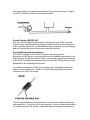
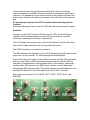
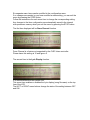
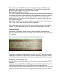
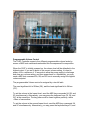
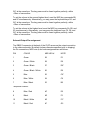
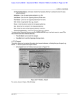
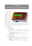
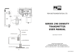
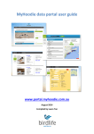
CLEF The MIDI Door Chime Controller
May 2013
Introduction
The Resonant Instruments CLEF is a MIDI based Door Chime Controller system.
Integrating a MIDI sequence recorder/ player, MIDI decoding, programmable
voltage solenoid drivers, and a door chime button interface. Direct MIDI through
play is also supported using the DIN MIDI input on the rear of the controller.
The CLEF has been designed for use with low voltage electrical, DC solenoid
driven, tubular Chime instruments. A maximum of twenty one individual striker
and damper solenoids are supported by the CLEF. The chimes are DC voltage
driven, at between 12 and 18 volts, using a 5.5 amp rated power supply.
Feature Summary
Completely integrated controller, enclosed inside a transparent polycarbonate
case.
Twenty Four (24) Character, dual line LCD display with thirty-two character
scrolling MIDI file name support.
Menu driven, seven button user interface. A removable SD Memory card for
storage of MIDI sequence files.
Ability to record and save MIDI sequence files generated by a MIDI enabled
keyboard, using the DIN connector at back of controller.
Programmable volume control in four steps using standard MIDI note commands.
Door bell button interface. Accepts standard 16vac transformer input from
existing doorbell wiring.
Specifications
The MIDI sequence recorder will auto start at the beginning of the first note
received, and will save the file data when the stop button is pressed. File format
is a non-standard MIDI channel 0. Existing MIDI files are not compatible with the
CLEF player format. All new material must be recorded using the CLEF
Controller.
The recorded MIDI file is saved as MMnnn.MID Files may be renamed by editing
the SD card file name on a PC that includes and SD card slot.
Solenoid Outputs are DC sink-only, rated 4 amps per channel maximum.
Programmable output voltage 12 - 18 Vdc in four linear steps.
Operation Voltage 18-20 Vdc, 5.5 Amps (using the included Power Supply).
Door Chime input voltage from existing transformer: 16 Vac maximum.
SD Flash Memory Card, 2gb Maximum, MMC compatible, FAT16 format.
Making Connections to the CLEF Controller
Disconnect the two 16 volt AC wires from the original mechanical door chime,
and attach the two wires to the two screw terminals on the back of the CLEF
controller.
Plug the DB25P cable connector into the DB25S socket on the back of the CLEF
Controller.
Insert the SD memory card. The SD card socket is a push-push type. To insert it,
simply push the card in until it locks into place, make certain the label on the card
faces up. To remove the card, push again to eject it.
Plug the 2.1mm coaxial power connector from the power supply into the socket
at the back of the CLEF controller.
Insert the AC power cord from the power supply into a 120vac wall receptacle.
Doorbell transformer
The CLEF Controller is compatible with a standard 12-16vac transformer.
Please use your existing doorbell transformer and wiring to activate the chimes.
The image below is a standard representation of your doorbell circuit. Connect
the CLEF controller in place of the original doorbell.
Doorbell Button -IMPORTANTUse only the LED lighted doorbell button included with your CLEF Controller.
Do not use an incandescent lamp lighted doorbell button as it will damage the
CLEF controller electronics. An incandescent lamp consumes too much energy,
and will overload the sensor electronics inside the controller.
Solenoid Blocking diode Installation
The CLEF Controller is a DC (Direct Current) output driver device.
Because it is a DC device, blocking diodes must be installed across each of the
solenoid coils. The blocking diodes serve to protect the output driver transistors
in the CLEF Controller from damage by the reverse EMF (Electro Motive Force)
generated by the collapsing electric field.
If you have purchased the CLEF in a controller only configuration without the
chimes, a set of twenty one 1N4001 or 1N4004 blocking diodes have been
included in the CLEF kit of parts.
The blocking diodes are a polarized device, and must be installed with banded
end toward the V+ (positive) rail of each solenoid. If you are unsure which side is
the common positive rail, please contact Resonant Instruments for assistance.
Chime solenoid racks are typically wired with both the striker and damper
solenoid connected in parallel. One blocking diode is adequate for each pair of
solenoids. The banded end of the diode connects to the positive rail side of the
solenoid pair, and the unbanded end connects to the other side of the solenoid
pair.
Do not attempt to operate the CLEF Controller without blocking diodes
installed.
Permanent damage will occur, and the CLEF will need to be returned for repair.
Operation
At power on, the CLEF controller will illuminate the LCD, and a small green
"standby" LED will be illuminated on the circuit board inside the controller
electronics, indicating the controller is operational.
The LCD display will show the name of the first file saved to the SD card, along
with the file number and the file size in bytes below the name.
The CLEF Controller is now ready for operation.
The MIDI sequence file displayed on the LCD will begin playing after pressing the
play button on the controller. Or, after pressing the doorbell button.
Each of the twenty one solenoid output drivers includes a yellow LED associated
with the output. When a MIDI sequence file begins playing, a yellow LED will
illuminate to indicate when a note has been struck on the chimes. Additionally,
another yellow LED serves as the MIDI activity indicator, and will flash when
decoding the MIDI sequence data. The activity indicator is located adjacent to the
standby LED indicator on the lower right corner of the CLEF controller.
Menu keys are arranged as UP, DOWN, LEFT, RIGHT, STOP, PLAY, and
RECORD.
Recording MIDI sequence files.
Pressing the RECORD menu button will place the controller in a ready to record
state.
The default name assigned to each file is MMnnn.MID whereas the three digit
value represents the file number. The file number is dependant on the number of
files already saved on the SD card. The controller will begin recording
immediately on detection of the first note received at the DIN connector. When
you are finished, press the STOP button to end recording. The file will be
concluded and written up to the last note played before the STOP button was
pressed.
Renaming the MMnnn.MID file
If you prefer, you may remove the SD memory card from the controller, and
insert it into a computer that includes an SD memory card reader. Edit the file
name from MMnnn.MID to anything you prefer under 32 characters as long as
the .MID extension remains on the file.
Deleting a MIDI sequence file
Pressing the LEFT and RIGHT menu keys simultaneously will immediately delete
the file currently shown on the LCD display.
WARNING: There is no menu safety protection from accidentally deleting a file.
If you want to protect all of the files on the SD memory card from accidental
deletion, please remove the SD card and move the memory protection switch to
LOCKED, then reinsert the card into the controller. You will not be able to record
new MIDI sequence files until the card has been unlocked.
Configuration Menu Settings
The controller includes an extensive list of menu features.
The CLEF Controller has been preset to function as a door chime system prior to
shipping. The controller will play the same single MIDI sequence for each
doorbell button press, with no delay at start. In the event you want to review the
menu settings, simultaneously press the UP and DOWN menu buttons to access
the configuration menu.
Six separate menu items can be modified in the configuration menu.
If no changes are needed, or you have modified a menu setting, you can exit the
menu by pressing the STOP button.
Follow the instructions for each menu item to change the corresponding setting.
Any changes to the item configuration are automatically saved to the internal
microprocessor memory when you exit the menu by pressing the STOP button.
The first item displayed will be Drum Channel function.
Drum Channel is a feature not supported by the CLEF chime controller.
Please leave this setting at 10 and ignore it.
The second item is the Lyric Display function.
It is recommended this item remain ON.
This menu item enables or disables the Lyric display (song file name) on the top
line of the LCD.
The LEFT or RIGHT menu buttons change the state of the setting between OFF
and ON.
The third item is the Mute function.
It is recommended this item remain OFF (all zeros).
The Mute feature allows the user to taper the volume of the MIDI sequence data
between 1 and 16 steps at start and end of file. The taper step is enabled with
the LEFT button, and the step rate position is incremented with the RIGHT menu
button.
This is a feature intended for audio accompaniment, and does not work well for
chime volume control.
The fourth item is the Repeat function.
It is recommended this item remain OFF for single play.
The LEFT or RIGHT menu buttons change the state of the setting between OFF
and the four menu choices.
The repeat feature allows for single play (recommended), repeat of same song,
play and repeat the entire directory, repeat continuously, or repeat all songs in
random order.
The fifth item is the MIDI Monitor function.
It is recommended this item remain in the BOTH setting.
The MIDI monitor is programmed to display the amplitude of each of sixteen
individual MIDI channels during playback, recording, or both.
The individual channel volume is represented as a seven step bar-graph at each
character location on the lower line of the display.
The LEFT or RIGHT menu buttons change the state of the setting between Off,
Record, Play, and Both.
The sixth item is the Track Delay function.
It is recommended this item remain at 0 (no delay).
The start of the MIDI sequence file can be delayed after the doorbell button press
for up to nine seconds.
The LEFT or RIGHT menu buttons change the value of the delay between 0 and
9 seconds.
Direct MIDI through play using the DIN connector
The chimes can be directly driven using a MIDI enabled keyboard instrument
transmitting sequence data on channel 0 (zero) whenever the CLEF Controller is
idle. Connect a DIN cable between the keyboard and CLEF controller for direct
through play. Your MIDI keyboard device may have channel 1 as the first
channel. If so, use channel 1.
The active keys on the MIDI keyboard correspond directly to the MIDI note #
assigned to each output of your chime scale. The note table is located in the
Solenoid output assignment at the back of this manual.
Wireless Infrared Remote Control
The CLEF Controller can be operated remotely via the included wireless remote.
A universal type remote control has been pre-programmed to allow for control of
song selection, Record, Play, Stop, and Pause when set to the AUX (DVD)
control at the top of the remote. If the buttons do not seem to work, make sure
AUX control is selected.
The CHAN+ and CHAN- are used to change the song selection. The lower keys
REC, PLAY, STOP, and PAUSE control the operations.
The configuration menu and file deletion must be performed from the controller
buttons. No other operation keys on the remote are supported by the CLEF.
Troubleshooting
In the event of problems, please check to make certain all connections are
securely made on the back of the controller, and the SD card is fully inserted into
the controller.
If the card is removed, the display will indicate the following error:
If the card is installed, and repeats the error after the CLEF Controller has been
restarted, this indicates the SD memory card has experienced an error. Please
contact Resonant Instruments for instructions on replacing the SD memory card.
Formatting an SD memory card
Any SD memory card with a capacity of 2gb or less can be used with the CLEF
controller.
I highly recommend SanDisk brand SD memory cards. These appear to have the
lowest defect and failure ratio of all the SD memory card brands tested.
The SD memory card must be formatted as FAT (16 bit data) only. Do not format
using FAT32, as the card will not be recognized during startup by the controller.
Chime striker timing period
The timing period used to activate a single strike of each chime tube is a fixed
programming length permanently saved in the MIDI decoder MCU FLASH
memory.
Normally, the MIDI note length would be active as long as the key is held down.
This convention does not work well in a chime application, and affects the quality
of the strike if held longer than the time necessary to strike the chime tube and
release.
Through extensive testing, I have determined that a strike pulse period length of
70ms (milliseconds) provides the best average timing period across all volume
levels, and minimizes any rattle that may occur with the dampers after striking.
If you believe the timing period may be too short or too long for your particular
application, the controller can be programmed to any timing period desired.
Please contact Resonant Instruments for instructions on returning the CLEF
Controller for programming.
Chime driver Voltage adjustment
There are three potentiometers related to chime volume control. Adjustments are
made through holes in the left side of the CLEF Controller to access ten turn
micro potentiometers using a small flat blade screwdriver inserted into the slot.
The CLEF Controller is shipped pre-adjusted to provide four linear volume steps.
If you find that the loudest volume setting is not be appropriate for your
environment, you can adjust the chime volume to meet your needs. The three
other volume steps will be scaled in reference to the main volume level, and not
require any further adjustments. The other volume steps only apply if you use
volume level commands in your MIDI sequence file data. See Programmable
Volume Control for information on using this feature in your compositions.
The main adjustment potentiometer, furthest toward the back of the CLEF
Controller is the volume control. Turning the potentiometer clockwise will
increase the voltage (volume level), and turning counter-clockwise will decrease
the volume level. A trial-and-error test method is best, in small quarter turn
adjustments.
Play a few different MIDI compositions to determine if the new setting is right.
Voltage adjustments A and B vary the linear divisions of the lower volume levels.
Do not make any adjustments to the A and B potentiometers, as they are
interactive and will affect the linear scaling of the lower volume steps.
Programmable Volume Control
The CLEF Controller supports four different programmable volume levels by
means of MIDI note commands embedded into the sequence file composition.
When the CLEF is initially powered on, the volume level will be defaulted to the
highest output. If you are in doubt of the current volume setting, it is best to
power off for a minimum of 15 seconds to allow the power supply to discharge
and clear any volume setting, and then power back on. Alternatively, you may
send a MIDI note command 5A, 5B, and 5C hex to manually assign the highest
volume setpoint.
The programmable Volume control is assigned by a two bit latch.
The most significant bit is 5B hex (G6), and the least significant bit is 5A hex
(F6*).
To set the volume to the lowest level, send the MIDI key commands 5A, 5B, and
5C simultaneously. Alternatively, you may press the keyboard keys F6, G6, and
G6* at the same time. The key press must be timed together perfectly, within
~50ms of one another.
To set the volume to the second lowest level, send the MIDI key commands 5A,
and 5C simultaneously. Alternatively, you may press the keyboard keys F6, and
G6* at the same time. The key press must be timed together perfectly, within
~50ms of one another.
To set the volume to the second highest level, send the MIDI key commands 5B,
and 5C simultaneously. Alternatively, you may press the keyboard keys G6, and
G6* at the same time. The key press must be timed together perfectly, within
~50ms of one another.
To set the volume to the highest level, send the MIDI key commands 5A, 5B, and
5C simultaneously. Alternatively, you may press the keyboard keys F6, G6, and
G6* at the same time. The key press must be timed together perfectly, within
~50ms of one another.
Solenoid Output Pin assignment
The DB25 S connector at the back of the CLEF serves as the output connection
to the chime solenoids. By default (unless otherwise specified prior to shipping)
the Pin connections, MIDI note #, and color assignment are as follows:
PIN
COLOR
MIDI HEX #
NOTE
1
Green
59
F6
2
Green / White
58
E6
3
Green / Black
57
D6*
4
Green / Black / White
56
D6
5
Blue
55
C6*
6
Blue / White
54
C6
7
Blue / Black
53
B5
-sequence reverse8
Blue / Red
4C
E5
9
Black
4D
F5
10
Black / White
4E
F5*
11
Black / Red
4F
G5
12
Black / Red / White
50
G5*
13
White
51
A5
14
White / Red
52
A5*
-sequence reverse15
White / Black
4B
D5*
16
White / Black / Red
4A
D5
17
Red
49
C5*
18
Red / White
48
C5
19
Red / Black
47
B4
20
Red / Black / White
46
A4*
21
Red / Green
45
A440
22
Orange
V+ output from controller
23
Orange / Black
V+ output from controller
24
Orange / Red
V+ output from controller
25
Orange / Green
V+ output from controller
* Designates sharp
Chime note scale programming
The default configuration for the CLEF Controller is A440 as the lowest note.
If your chimes are arranged differently, please advise me at the time of order and
the controller will be programmed to match your particular chimes.
Chime hanging pattern
If you have ordered a set of 21 chimes with the CLEF Controller, the hanging
pattern can be configured in any way you desire. Popular choices are; Inverted
V, Normal V, Lowest note left, and Lowest note right. Please contact me at
Resonant Instruments for more information on the hanging pattern.
Warranty
The Resonant Instruments CLEF MIDI Chime Controller is covered by a one (1)
year warranty against defects in materials and workmanship.
Damage caused by misuse, lightning, or failure to install blocking diodes for
output transistor protection are not covered by the warranty.
Please contact Resonant Instruments by telephone at 480-516-4523 for
assistance or information. Or you can email me at: [email protected]