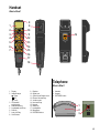
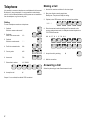
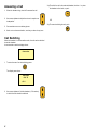
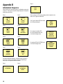
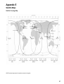
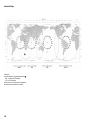
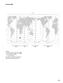
1
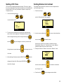
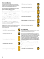
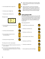
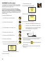
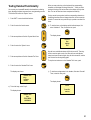
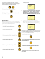
SAILOR SP4400
Operating Instructions
Distress Call, see page ii. List of contents, see page 1.
DISTRESS Call From Handset DISTRESS Call From Button
1. Hook off the handset.
1. Open DISTRESS lid.
2. Open DISTRESS lid on hook.
2. Press button for 5 seconds.
3. Press DISTRESS button
for 5 seconds.
3. Release button when tone signal stops.
DISTRESS
5 seconds to
Distress
Alert
4. Release the button when the display shows:
ENTER TEL.NO
OR PRESS #
_
4. If the telephone connected to the button is on
hook, it starts ringing. Then hook off the
telephone.
5. · Enter number for DISTRESS call, followed by
# key, or
· Enter # key to start a DISTRESS call to
default Coast Earth Station (CES), or
· Wait about 15 seconds, then handset automatically starts a DISTRESS call to the
default CES.
5. Hook off handset if on hook.
6. · Enter number for DISTRESS call, followed by
# key, or
· Enter # key to start a DISTRESS call to default
Coast Earth Station (CES), or
· Wait about 15 seconds, then handset automatically starts a DISTRESS call to default CES.
7. Wait for connection to Rescue Coordination
Centre (RCC).
8. Provide the RCC with the necessary information
about the ship name, call sign, MMSI, position
(unless using a GPS), what is wrong, number of
crew, and anything else of importance.
ii
6. Wait for connection to Rescue Coordination
Centre (RCC).
7. Provide the RCC with the necessary information
about the ship name, call sign, MMSI, position
(unless using a GPS), what is wrong, number of
crew, and anything else of importance.
Handset
What Is What?
1
8
9
2
3
10
11
4
5
12
13
6
7
14
15
19
16
17
18
Telephone
What Is What?
1. Display
2. Indicator lamps
Power
Call
In use
3. Call transfer/
switching key
4. Address Book key
5. Loudspeaker on/off key
6. Shift key
7. Lock on/off key
8. On/off button
9.
10.
11.
12.
13.
14.
15.
16.
17.
18.
19.
Earpiece
Signal level
Opens Ocean Region menu
Escape / idle state key
Volume control
Hook on/off key
Keypad
Select key
Loudspeaker
Microphone
DISTRESS button
1. Handset
2. Keypad
3. DISTRESS button
1
2
3
iii
Introduction
About this Manual
Congratulations on your new SAILOR SP4400 accessories.
This manual is for the daily user of the system in voice mode.
The manual includes instructions for both use of telephones and
handsets in the Inmarsat B 4400 system. The manual is divided into
3 sections.
· Section # 1 describing DISTRESS calls.
· Section # 2 describing simple use, incl. how to make and answer
a call.
· Section # 3 describing advanced operation/functions of the
handset.
Your SAILOR SP4400 system is a modular system containing aerial,
transmitter/receiver, handset, printer, standard telephone/switch
board, fax, telex terminal, alarm unit, alarm button and/or personal
computer.
The SAILOR SP4400 system can be operated from the handset and/
or a telephone in voice mode. You can connect up to five handsets
and two telephones to your SAILOR SP4400 system. The standalone alarm button (for distress purpose) is used in connection with
the telephones. In connection with the handset, the DISTRESS key
is placed on the hook.
Sailor marine equipment is specially designed for the extremely
rugged conditions on bord a ship, based on more than 50 year’s
experience with all kinds of boats, from small pleasure crafts, over
fishing boats working under all climatic conditions, to the biggest
ships.
S.P. Radio A/S is one of Europe’s leading manufacturers of maritime
radio communication equipment, a position which has been maintained by means of constant and extensive product development.
We have a worldwide network of dealers with general agencies in
more than fifty countries. All our dealers are specially trained to
service all your Sailor products.
iv
Please note
Any responsibility or liability for loss or damage in connection with
the use of this product and the accompanying documentation is
disclaimed. The information in this manual is furnished for informational use only, is subject to change without notice, may contain
errors or inaccuracies, and represents no commitment whatsoever.
This agreement is governed by the laws of Denmark.
Doc. no.: B4345GB0
Issue: D/0013
Contents
DISTRESS Call From Handset ............................................ ii
DISTRESS Call From Button .............................................. ii
Handset ................................................................................ iii
What Is What ? ................................................................ iii
Telephone ............................................................................ iii
What Is What ? ................................................................ iii
Introduction ......................................................................... iv
About this Manual .............................................................. iv
Contents ............................................................................... 1
Basic Information ................................................................ 1
Inmarsat Satellite System ................................................ 1
Coast Earth Stations ........................................................ 1
Abbreviations ................................................................... 1
Telephone ............................................................................. 2
Making a Call ................................................................... 2
Answering a Call .............................................................. 2
Handset, Simple Operation ................................................ 3
Handset States ................................................................ 3
Handset Power On/Off ..................................................... 3
Unlocking Handset ........................................................... 3
Call Functions .................................................................. 4
Making a Manual Call, Example ...................................... 5
Answering a Call .............................................................. 6
Call Switching .................................................................. 6
Handset, Advanced Operation ........................................... 7
Address Book ................................................................... 7
Calling a Number From Address Book ............................ 8
Last Number Redial ......................................................... 8
Auto Call Transferring ...................................................... 8
Security Lock Function .................................................... 9
Setting UTC Time ............................................................ 11
Setting Dimmer & Contrast ............................................. 11
CES, TN Id, Ocean Region and Position ...................... 12
The Function Menus .......................................................... 14
Function Overview ......................................................... 15
Extension Number ......................................................... 16
Local Number ................................................................. 16
Call Groups .................................................................... 17
Setting Default CES ....................................................... 18
DISTRESS Test Procedure ............................................ 20
Testing Handset Functionality ........................................ 21
System Test .................................................................... 22
Appendix A ......................................................................... 23
User Access Levels ........................................................ 23
Appendix B ......................................................................... 24
Initialisation Sequence ................................................... 24
Appendix C .........................................................................
System Test ....................................................................
Appendix D .........................................................................
CES Codes, Names and Operators ..............................
Appendix E .........................................................................
Satellite Maps ................................................................
Appendix F .........................................................................
Tone Signalling ...............................................................
25
25
26
26
27
27
30
30
Basic Information
Inmarsat Satellite System
The Inmarsat satellite system consists of four satellites.
The Inmarsat satellite system is a worldwide communications
system covering the area from 70°S to 70°N or more. The system
contains four geostationary satellites placed above the equator, each
satellite remaining in the same relative position to the earth. Each
satellite covers a part of the earth, called an Ocean Region:
·
·
·
·
Atlantic Ocean Region East (AOR-E), 15.5°W
Atlantic Ocean Region West (AOR-W), 54°W
Pacific Ocean Region (POR), 178°E
Indian Ocean Region (IOR), 64.5°E
Coast Earth Stations
Your Inmarsat B terminal is referred to as a Ship Earth Station (SES)
in the Inmarsat system. Linking and routing connections through the
public telecommunications network is done by a Coast Earth Station
(CES). All coordination of the satellite traffic is done by a Network
Coordination Station (NCS).
The Inmarsat B system includes telephone, facsimile, telex and data
communication. At each Coast Earth Station one or more Network
Operators provide some or all of the Inmarsat B facilities. The user
can select which Network Operator he wants to use by specifying a
CES access code in the call.
Abbreviations
CES
CU
GPS
NCS
RCC
SES
TN Id
Coast Earth Station
Control Unit
Global Positioning System
Network Coordination Station
Rescue Coordination Centre
Ship Earth Station
Terrestrial Network Identification
1
Making a Call
Telephone
It is possible to connect a telephone or a switchboard to the Inmarsat
B terminal. If using a telephone, it is only possible to make simple
calls. A lot of the advanced features in the system are not accessible
from the telephone, e.g. the security lock.
1. Hook off the receiver and listen for the tone signal.
2. Busy tone: Hook on and try again later.
Ready tone: The phone is ready for calling.
3. Optional; enter CES access code, for example Laurentides:
Dialling
To enter a telephone number on a telephone:
1. Optional
Switch to access code mode *
2. Optional
Enter CES access code
13
3. Optional
Switch to number mode
* *
4. Prefix for automatic calls
00
5. Country code
45
* 1 3 * *
4. Enter the wanted number including prefix for automatic calls,
country code and area code, for example who has telephone no.
7013 7000 in Denmark:
0 0 4 5 7 0 1
3 7 0 0 0
5. Accept the call by entering:
6. Area code
#
70
6. Wait for connection.
7. Subscriber’s number
137000
Answering a Call
When the phone rings, hook off and answer the call.
8. Accept the call
#
If steps 1-3 are omitted, the default CES is selected.
2
Handset, Simple Operation
In Active State:
a) The display shows the following:
Up to five handsets can be connected to the Inmarsat B terminal.
Each handset can be in one of 3 states, active, passive and
disabled. Only one handset can be in the active state, the handset
currently in use.
Handset States
Ready
Hook Off And
Enter Number
b) The “Power” indicator lamp flashes twice every second.
The normal display and signalling of the handset are:
Handset Power On/Off
In Disabled State:
If you want to toggle the handset’s power on/off condition, simply:
a) Display is cleared and the light is turned off.
b) The “Power” indicator lamp gives a short flash every 5 seconds.
1. Press and hold the on/off button.
In Passive State:
2. Wait 3 to 5 secounds for either a continuous tone signal or the
“Power”, “Call” and “In use” indicator lamps to be turned on
simultaneously.
a1) If the handset is ready for operation, the display shows one of
the following read-outs, depending on the security lock state:
Lock = Enabled
Lock = Disabled
Ready
Ready
Press a Key
To Activate
Hook Off And
Enter Number
a2) If the system is occupied by another handset, this is displayed;
for example a connection established from handset 2 will show
the following display in the passive handsets.
OCCUPIED
CONNECTED
By CU 2
If the line is being used by another service on the Inmarsat B
terminal - e.g. telex - this appears from the passive handset
display.
3. Release the button.
Unlocking Handset
If security lock is turned on, the user has to key in a pin code before
the handset can be forced into the active state. The security lock
state is indicated by the key icon and the displayed text in passive
state. With security lock on, the display shows:
Ready
Press a Key
To Activate
Having pressed any key, the user is asked to pick a user name from
a list. The user name determines which facilities the user has access
to. Furthermore the user name is stored in the call log for later use.
Not Ready
Line Busy
By Telex
b) The “Power” indicator lamp is turned off shortly every 5 seconds.
3
To disable the lock:
Call Functions
1) Press any key to see the user list:
Speaker, earpiece and microphone
The earpiece is always turned on. The microphone is always in the
opposite state of the speaker (ON if speaker OFF). The speaker icon
on the display shows the state of the speaker.
Select
User ID
>Captain
2)
Use arrow up and down to pick the right user name.
Use the speaker key to toggle the state of the speaker and
the microphone.
Hook and hook key
Before initiating a call, you have to hook off. This can be done by
lifting the handset out of the hook or by activating the hook key. The
hook icon on the display shows the state of the hook.
Hook on
3) Press SELECT key to select the user name.
4) Key in the pin code corresponding to the user name.
Hook off
ENTER
PINCODE
If no hook icon is shown, the hook is on.
***
Volume regulations
The volume in the speaker and earpiece can be adjusted
during conversation by arrow up/down.
5) Press SELECT key to finish pin code entry.
Telephone
Unlocked
Manual telephone call dialling
To enter a telephone number on the handset:
1. Optional
Terrestrial network ID
1*
followed by dial string separator
Then the display shows:
Ready
Hook Off And
Enter Number
If the handset has not been used for some time, the state is forced
from active to passive, enabling the security lock if used. The
amount of time it takes before the handset is forced into passive
state, can be set up from within the function menu.
4
2. Optional
CES access code
13*
followed by dial string separator
3. Prefix for automatic calls
00
4. Country code
45
5. Area code
70
6. Subscriber’s number
137000
7. Accept the number and start calling
#
If 1 and/or 2 are omitted, the default network and CES respectively
are selected. (See Setting Default CES, page 17)
Making a Manual Call, Example
1. If the display shows:
a)
Ready
2. Enter the total number you want to dial, including Network ID,
CES code and separators if necessary, using the numeric keys.
Left arrow deletes last entered digit. For example, to call the
subscriber who has telephone no. 7013 7000 in Denmark:
ENTER
Telephone No
004570137000
_
3. Accept the number and start calling by the # key.
4. The earpiece/speaker will make a dialling tone and the display
will show:
CALLING
Press a Key
To Activate
- the handset is locked. Follow the instructions on how to unlock it.
5. When connection is established, the audio is routed through and
the display shows:
b)
Not Ready
Conversation
Line Busy
By Fax
- the line is occupied (in this example by a fax). Wait until the line
is free again.
6. When either party taking part in the conversation hangs up, the
other user will hear a busy tone. Also, the display will indicate
that the call has been ended and that the handset should be
hooked on.
c)
Ready
Hook Off And
Enter Number
- hook off the handset. The display will show:
ENTER
Telephone No
_
- and you will hear a dialling tone.
CALL
TERMINATED
LOCAL
HOOK-ON
7. After every call, its duration is shown on the display:
LAST
DURATION
00:02:35
The call duration is also stored in the call log, together with user
name and called telephone number.
5
Answering a Call
1. When the handset rings, hook off to answer the call.
2. Use arrow up/down to adjust the volume in earpiece or
loudspeaker.
3.a)To switch the call to the selected handset, hook on - i.e. place
the handset on the hook, or push:
OR
3.b)To cancel switching the call, push:
3. Communicate as on an ordinary phone.
4. Hook on to end communication, or when you hear a busy tone.
Call Switching
When the handset is in conversation mode, the call can be switched
to another handset.
In conversation mode the display shows:
Conversation
1. To enter the menu for call switching, press:
The display now shows:
SWITCHING
CALL TO
> CU 1
2. Use arrow up/down to find the handset (= CU number)
to which the call should be switched.
6
Handset, Advanced Operation
There are numerous possibilities of more advanced operation of the
system. The most frequently used functions are carried out by
means of special buttons or shifted numeric keys. The less frequently used functions are shown in the function menu tree on page 15.
Example:
Key
to search through alphabetical range “A”-”C”.
Key
to search through alphabetical range “D”-”F”, and
so on. When the last entry in the range has been reached, the
first entry in the range will be shown again.
Address Book
In the Address Book the following facilities are implemented:
·
·
·
·
·
·
The Address Book can hold up to 99 entries with numbers and
names. A telephone number can consist of maximum 22 digits,
and a name may be up to 12 characters.
Any of the 99 stored telephone numbers can be used to initiate a
call.
Each entry in the Address Book can be deleted.
New entries can be added to the Address Book as long as some
of the 99 entries are free.
The number stored in every entry can be changed.
It is possible to carry out alphanumeric search through the stored
entries.
To enter, push the Address Book key. Then the following menu
appears:
ADDRESS BOOK
John
12345678
Changing a stored number in the Address Book
1. Push Address Book key.
2. Use arrow up/down to select the wanted entry in the
Address Book (see above).
3. Push the SHIFT key to enter the shifted functions.
4. Push 1 key to select EDIT mode.
5. Use the numeric keys to enter a new number.
6. Push # key to store the new number.
Searching the Address Book
To find a stored entry in the Address Book, simply:
Entering new number and name in Address Book
1. Push Address Book key. The Address Book will show the
last used entry.
1. Push Address Book key.
2.a) Use the arrow up/down key to search alphabetically
through all the entries in the Address Book. When the
last entry has been reached, the first entry is shown
again
2. Push the SHIFT key to enter the shifted functions.
OR
2.b)Use one of the numeric keys to search alphabetically through a
specific range of the Address Book.
3. Push 2 key to select STORE mode.
4. Use the numeric keys to enter the number.
5. Push # key to store number.
7
6. Use the alphanumeric keys to enter the name corresponding to
the number.
Last Number Redial
7. Push # key to store the name.
1. Hook off the handset to enter telephone number entry mode.
Deleting a stored entry in the Address Book
2. Push 0 key to give code for last number.
When ready to enter a telephone number:
1. Push Address Book key.
3. Push # key to show the last called number.
2. Use arrow up/down to select the wanted entry in the
Address Book (see above).
4. Push # key again to start initiating the call.
The handset will generate a ringing tone; follow the description in
Making a Manual Call, Example 4-6 (page 5).
3. Push the SHIFT key to enter the shifted functions.
Auto Call Transferring
4. Push 3 key to select the DELETE mode.
5. Push # key to delete the selected entry.
When a handset receives a selective ship originated call, and the call
is not answered, the call can automatically be transferred to another
handset. The auto transferring parameters can be set up individually
for each handset.
The handset has to be in ready mode, where the display will typically
show:
Ready
Calling a Number From Address Book
To call a number stored in the Address Book:
Hook Off And
Enter Number
1. Push Address Book key.
1. To enter the menu for auto transferring, push:
2. Use arrow up/down to select the wanted entry in the
Address Book.
3. To start initialling the call:
•
Hook off the handset to start initialling the call, or
•
Push the hook key.
The handset will generate a ringing tone; follow the description in
Making a Manual Call, Example, 3-6 (page 5).
The display now shows:
TRANSFER
> Mode : Off
To CU :
1
Delay : 30 s
As appears from the above read-out, you can now choose among
“Mode”, “To CU”, and “Delay”.
2. To enable/disable auto transferring mode, select “Mode”.
3. To specify which handset (= CU number) the call should be
transferred to, select “To CU”.
8
4. To specify the time in seconds (0-60) that the call should ring
before it is transferred to the specified handset, select “Delay”. If
the delay is set to 0 seconds, the call is transferred immediately;
there will not even be a ringing tone in the first handset before
the call is transferred to the next.
Disabling Security Lock
By default, the transceiver is set up with security lock enabled, and
with the user entries listed above. The pin codes of the default user
ID’s are included in the documentation. To disable security lock, the
user has to be identified with a priority value of 4 or less (Commander, Captain or super user). To select the item for disabling
security lock from the function menu:
Security Lock Function
The handset can be protected against unauthorized use by security
lock. Security lock works together with a list of user ID’s and
corresponding pin codes. Security lock requires that the user selects
his user ID from a list, and then keys in his personal pin code, before
the handset can be used to generate a call.
1. Push SHIFT key to enter the shifted functions.
The security lock function ensures that only users recognized by the
system can unlock the handset and make calls through the Inmarsat
system.
3. Push # key to enter the “Setup” menu.
Answering incoming calls is not protected by security lock. Furthermore sending a distress priority call can also be done regardless of
the security lock.
2. Push 8 key to enter the function menu.
4. Use arrow up/down to select the “Security” item.
It is possible to disable the security function in the setup menu.
5. Push # key to enter the “Security” menu.
User ID List
Every user specified in the system is given a priority value. The
priority value determines what the user is allowed to do in the
system. By default, the user list contains 6 entries with different
priority values. The 6 default users are shown below.
User ID
683(586(5
&DSWDLQ
&RPPDQGHU
2IILFHU
&UHZ
3DVVHQJHU
6. Push # key again to select “On/Off” item.
3ULRULW\YDOXH
The super user has the highest priority in the system and is therefore
not restricted in any action. The super user can edit all other users.
Each facility/function in the handset has a priority value. The priority
value of the facility item and the user’s priority value determine
whether the user has access to the item or not. (See Appendix A)
The user ID is written in the call log so it is possible to identify who
has made which calls.
7. Push arrow down to select “Disable Lock” item.
8. Push # key to enter “Disable Lock” menu.
9. Use arrow up/down to select the default user of the
system.
10. Push # key to accept security lock disabling.
9
With security lock disabled, the handset is ready for use for everyone without any identification of the user. To avoid misuse of the
handset’s facility, the user who disables the security lock is asked to
set the priority value. This is done by selecting a user ID from the
user list. This user ID is then used as the default user of the
unlocked system.
Enabling Security Lock
10. Use numeric keys 0-9 to enter the pin code, and finish entering
with the # key.
The user has to pick a user ID with a priority value of 4 or less to
enable security lock.
If security lock has been disabled as described above, it can be
enabled again in the following way:
If the handset is left unused for some time, it automatically turns into
locked state. The user then has to log on again to use the handset.
1. Push SHIFT key to enter the shifted functions.
The user can also force the handset into locked state by pushing the
following two keys:
2. Push 8 key to enter the function menu.
3. Push # key to enter the “Setup” menu.
The user has to accept entering the security lock state, and the
following is displayed:
Press # TO
Lock
Telephone
4. Use arrow up/down to select the “Security” item.
The user can regret entering the security lock state by pushing the
5. Push # key to enter the “Security” menu.
ESCAPE key
, after which the handset will return to the
6. Push # key again to select “On/Off” item.
active state. If the user presses the SELECT key
7. Push # key again to select “Enable Lock” item.
, the
handset is forced into the passive state. The display shows the
following and the “Lock” icon is turned on:
Telephone
is locked
8. Use arrow up/down to select your user ID.
9. Push # key to accept your choice.
To use the handset again, the user has to go through user identification again.
Deciding which users are allowed to use the system is done from the
“Setup” menu by selecting the “Security” item.
10
Setting UTC Time
Setting Dimmer & Contrast
UTC time can be displayed/adjusted manually. The time is used in
the call log. Adjusting the time requires that the user is identified with
a priority value of 4 or less (Commander, Captain or super user).
To adjust the time:
The background light and the contrast level can be adjusted from
the “Dimmer/Light” menu.
1. Push the two keys:
1. Push the following two keys:
and the “Dimmer/Light” menu appears:
to enter the time menu
DIMMER/LIGHT
> On/Off
Dimmer
Contrast
UTC TIME
08:25
31-01-1997
2. The time menu contains: hour, minute, day, month and year,
each of which can be adjusted. The display will flash to show
2. Use the arrow up/down key
to move to the desired item
where changes are being made. Using the arrow right
and use # key
and left
to select the item.
keys will change to the next or previous item.
Selecting the “On/Off” item enables or disables the light.
Selecting the “Dimmer” or “Contrast” item, a menu makes it
possible to adjust the level of each of these.
Using the arrow up and down key
will change the value
3. Example: Select the “Dimmer” item for the “Dimmer” menu:
DIMMER/LIGHT
Dimmer
of an item.
zzzzz
3. When editing is finished, enter the SELECT key
changes will take effect. Entering the ESCAPE key
and the
will
cancel the changes.
Use the arrow up/down key
to increase or decrease
the “Dimmer” level.
4. Push the # key
for the changes to take effect.
11
CES, TN Id, Ocean Region and
Position
To view the current Ocean Region and CES, push the CES key
6. Use arrow up/down to find the new CES.
and the following display appears:
7. Push # key for new CES to take effect.
East Atlant
Comsat
> Change
Exit
The first line shows Ocean Region. The second line shows CES (for
normal calls).
User identified by a priority value of 4 or less (Commander, Captain,
or super user) may change the Ocean Region, CES, and TN Id as
well as key in the position by selecting the “Change” item.
If the default CES for distress calls and stand alone calls have to be
changed, this must be done from the “Setup” menu.
Changing TN Id
To change the TN Id of the default CES:
1. Push the CES key to view settings.
2
Use arrow up/down to indicate “Change” item.
Changing CES
To change CES for normal calls:
1. Push the CES key to view settings.
2
Use arrow up/down to indicate “Change” item.
3. Push # key to select the “Change” menu.
4. Use arrow up/down to find “TN Id” item.
3. Push # key to select “Change” menu.
5. Push # key to select “TN Id” menu.
4. Use arrow up/down to find “Earth Station” item.
6. Use arrow up/down to change TN Id.
5. Push # key to select “Earth Station” menu.
7. Push # key to let the new TN Id take effect.
If the TN Id of the CES for distress calls and stand alone calls has to
be changed, this must be done from within the “Setup” menu.
12
Changing Ocean Region (satellite)
To change Ocean Region:
1. Push the CES key to view settings.
Manual Position Setting
When the system searches for a satellite, the position has to be
known. Normally the position is given from a GPS, but it is also
possible to key in the position manually. This is done by the following:
1. Push the CES key to view settings.
2. Use arrow up/down to find “Change” item.
2. Use arrow up/down to find “Change” item.
3. Push # key to select “Change” menu.
3. Push # key to select “Change” menu.
4. Use arrow up/down to find “Ocean Region” item.
4. Use arrow up/down to find “Position” item.
5. Push # key to select “Ocean Region” item.
5. Push # key to select “Position” menu and the following menu
appears:
SET
POSITION
N: 00:00
E: 000:00
6. Use arrow up/down to find new Ocean Region.
7. Push # key for new Ocean Region to take effect.
8. Use arrow up/down to find the CES in the new Ocean Region.
The “Position” menu contains 6 pieces of information, each of which
can be adjusted. The display will flash to show where such changes
are being made. Use the arrow right
and left
keys
to move back- and forwards. To change the value of an item, use
9. Push # key to let new CES take effect.
Changing Ocean Region forces the system to carry out a new
search for the satellite in the region. This may take a while.
the arrow up/down keys
or the numeric keys to change
numeric values.
When editing the position has been finished, push the # key and the
new position will take effect.
13
The Function Menus
The handset contains several functions for changing the system
settings, showing the status of some system parameters, configurations, and testing the system.
To enter the function menu system push the following two keys:
Then the main menu of the functions appears:
FUNCTION
>Setup Menu
Status Menu
System Menu
The functions in the system are divided into three categories:
SETUP MENU: Containing all functions for changing system
parameters, such as volume, ringing tone, language, user names
and pin codes.
STATUS MENU: Containing all functions for viewing system
parameters, such as versions, use of the system and system
parameters.
SYSTEM MENU: Containing all functions needed for the system
administrator/super user to test and configure the system.
In each menu, you can
•
Step up/down by
•
Select items by
•
Go up one level without selecting by
or simply wait 7-8 seconds for the menu
to step up one level automatically.
14
In the table on page 15 is given a total list of entries available in the
function menu system.
If an entry in the function menu system is marked by an asterisk (*),
the user is identified by a priority value that does not give him access
to the item.
Function Overview
Function Menu 1st submenu
Setup Menu
Ringing Tone
Key Beep
Language
CES
Security
2nd submenu
3rd submenu
4th submenu
Volume
Ringing Tone
Deep
High
Toggle Slow
Toggle Fast
Deep Dual
High Dual
Test
Volume
Enable
Disable
English
Danish
Default
For Voice
Distress
Stand Alone
Rename
TN Id
On/Off
Enable Lock
Disable Lock
Prev
Set Pincode
Setup Users
Edit
Set Pincode
Set Status
Add
Delete
Areas
Show Areas
Auto Areas
User Areas
Status Menu
Groups
SW Versions
Call Log
Show
Control Unit
Transceiver
Aerial
Global
Private
System Menu
Eb/N0
Eleva/Azim.
Distre Test
System Test
Configure
Start
Cancel
Overview
List
Call Groups
Extension
Local nr.
Select Code
Handset Tst
InAct Timer
Keys
Indicators
Sounds
Enable
Disable
User Area 1
User Area 2
User Area 3
User Area 4
View
Delete
View
Total
Clear
CU
Phone 1
Phone 2
Button 1
Button 2
Automatic
Manual
5th submenu
Enabled
Disabled
Action
Increases or decreases ringing volume
Selects one deep ringing tone every 5 seconds
Selects one high ringing tone every 5 seconds
Selects 5 deep/high toggled ringing tones every 5 seconds
Selects 20 deep/high toggled ringing tones every 5 seconds
Selects 2 deep ringing tones every 5 seconds
Selects 2 high ringing tones every 5 seconds
Continues testing of selected ringing tone
Increases or decreases volume of key beep
Enables key beep
Disables key beep
Switches all text to English
Switches all text to Danish
Sets default CES used for normal calls
Sets default CES used for DISTRESS calls
Sets default CES used for stand-alone calls
Edits CES names
Changes TN Id for CES
Enables security lock, giving user ID and pin code
Disables security lock, specifying default user ID
Steps backwards in the menu. No changes
Changes pin code of current user
Changes pin code of another user
Enables user ID to be used with login
Disables user ID; to log in, use standard ID
Specifies name, priority and pin code of new user
Deletes user ID from list
Shows the current area
Enables automatic area changes
Disables automatic area changes
Sets user defined area no. 1
Sets user defined area no. 2
Sets user defined area no. 3
Sets user defined area no. 4
Shows the current group ID
Displays the version no. of the handset unit
Displays the version no. of the transceiver unit
Displays the version no. of the aerial unit
Displays the entries in the global call log
Deletes all entries in the call log
Displays the entries in the call log of current user
Displays total number of calls and duration of current user
Clears totals above of current user
Shows continuously the value of Eb/N0
Shows continuously the value of elevation and azimuth angle
Initiates a DISTRESS test call
Steps backwards in the menu. No changes
Generates an overview of the system warnings and errors
Steps through all system tests, pausing for every warning and error
Sets status, number and mode for call groups
Specifies extension no. of handset
Specifies extension no. of phone 1
Specifies extension no. of phone 2
Specifies extension no. of DISTRESS button 1
Specifies extension no. of DISTRESS button 2
Sets local number for current handset
Selects default CES automatically
Default CES has to be selected manually
Sets time before unused handset is forced inactive
Manual test of all keys
Visual test of all indicators and icons
Test of each of the four frequencies
15
Extension Number
Your Inmarsat B terminal’s handsets, phones, and DISTRESS
buttons have extension numbers. When initiating the system, the
extension number of each handset/phone has to be set.
6. Push # key to enter “Configure” item.
7. Push # key to enter “Extension” item.
The extension number of each handset/phone has to be unique
because it represents an address in the system.
The extension number of the DISTRESS button, on the other hand,
indicates a connection to a phone or the telex terminal.
When a DISTRESS call is initiated from a DISTRESS button
connected to a phone, a DISTRESS priority call is (automatically)
sent, and an audio signal is generated on the connected phone,
indicating that the user hooks off and answers the RCC. If, for some
reason, the system cannot find the connected phone, the audio
signal is generated in all handsets/phones, and the first to hook off
gets the line.
When a DISTRESS call is initiated from a DISTRESS button
connected to the telex terminal, a DISTRESS priority call with preentered parameters is sent automatically.
Setting up extension numbers of the current handsets, phones and
DISTRESS buttons is done from within the system menu by
following these instructions:
1. Push SHIFT key to enter the shifted functions.
2. Push 8 key to enter function menu.
3. Use arrow up/down to select “System” menu.
4. Push # key to enter “System” menu.
8. Use arrow up/down key to select the item whose
extension is to be changed.
9. Push # key to enter selected item.
10. Use arrow up/down key to change the value of the
extension number.
11. Push # key for the change to take effect.
Local Number
For each handset it is possible to specified a local number. The local
number is only used in connection with call groups.
The local number of each handset/phone has not to be unique as in
case of the extension number. The local number indicate what ID the
handset/phone is using as identification to the Inmarsat system when
making a call or responding to a incoming call, provided that the
current local number is member of a enabled call group. If the local
number for a handset/phone is not member of a enabled call group
or the call group is disabled, the extension is used as identification to
the Inmarsat system.
The local number for a PSTN phone (connected to X41 or X42) is
always the same as the extension number and can not be changed.
The local number for a handset can be changed from within the
system menu by following these instructions:
5. Use arrow up/down to select “Configure” item.
16
1. Push SHIFT key to enter shifted functions.
Call Groups
2. Push 8 key to enter function menu.
3. Use arrow up/down to enter “System” menu.
When configuring the system, Inmarsat will assign one or more
telephone numbers to the system, where some or all can be
dedicated for voice purpose. Every number assigned to the system
is identified by a ID (normaly the ID is equal to the extension of the
equipment).
It is possible to let several handsets/phone refer to the same
Inmarsat ID. This is done by setting up call groups. It is possible to
set up 8 call groups. Each call group can include one phone and
several handsets.
4. Push # key to enter “System” menu.
A call group consist of 3 parameters:
· Status
· Number
· Mode
5. Use arrow up/down to select “Configure” item.
Status can be set as On or Off (enabled/disabled) and indicates
whether or not the group is used.
6. Push # key to enter “Configure” item.
Number shall be set equal to the Inmarsat ID assigned to the system
as a voice number.
7. Use arrow up/down to select “Local Nr” item.
Mode can be set as Dedicated or Common. When dedicated only the
first phone or handset found in the call group, will receive incoming
calls for the specified number. When mode is set to common, all
phone and handset in the call group will receive incoming calls for
the specified number.
Setting up call groups is done from within the system menu by
following these instructions:
8. Push # key to enter “Local Nr” item.
1. Push SHIFT key to enter shifted functions.
9. Use arrow up/down to change the value of
the local number.
2. Push 8 key to enter function menu.
10. Push # key for the change to take effect.
3. Use arrow up/down to enter “System” menu.
4. Push # key to enter “System” menu.
17
5. Use arrow up/down to select “Configure” item.
6. Push # key to enter “Configure” item.
7. Push # key to enter “Call Groups” item.
The display will show:
CALL GROUP 1
> Status:
Off
Number :
1
Mode :
Com
·
If the local number for a handset can’t be found in any enabled
call group, the extension for the handset is used as Inmarsat ID
for outgoing calls.
·
When the Inmarsat ID for a incoming call is specified as a
dedicated call group, the phones is always evaluated first for a
member of the call group. If no phones are member of the call
group the handsets are evaluated. If no handsets are found as
member of the call group, the call will be send to all handsets.
Setting Default CES
When the user is initiating a call, it is optional to enter a specific CES
ID. If CES ID is omitted when initiating the call, the system automatically inserts the ID of the default CES. The user has the possibility of
changing the default CES. The default CES is specified for each of
the 4 Ocean Regions and for normal calls, DISTRESS calls and
stand alone calls.
When specifying default CES:
8. Use arrow up/down to scroll true the parameters for
all 8 call groups.
1. Push SHIFT key to enter shifted functions.
2. Push 8 key to enter function menu.
9. Push # key to enter selected parameter.
3. Push # key to enter “Setup” menu.
10. Use arrow up/down to change the value for
the selected parameter.
4. Use arrow up/down to select “CES” item.
11. Push # key for the change to take effect.
5. Push # key to enter “CES” item.
The following rules have effect, using call groups:
6. Push # key to enter default item.
·
When all call groups is disabled (factory default), the extension is
used as inmarsat ID.
·
The local number for phones (connected to X41 or X42) is the
same as the extension and therefor two phones can’t be member
in the same call group.
18
7. Use arrow up/down key to select Ocean Region.
8. Push # key to enter selected Ocean Region.
9. Push arrow up/down key to select service type (voice,
DISTRESS, stand alone).
10. Push # key to enter selected service type.
11. Push arrow up/down key to select default CES.
12. Push # key to accept selected default CES.
19
DISTRESS Test Procedure
Your Inmarsat B terminal can test the DISTRESS call by changing
the DISTRESS flag from DISTRESS real mode to DISTRESS test
mode. This is done in the “System” menu.
A DISTRESS test call has to be initiated within 30 seconds,
otherwise the DISTRESS flag is changed back to real DISTRESS
mode. Furthermore the DISTRESS test call has to be cleared within
120 seconds from the selection of the test mode. After 120 seconds,
the system automatically changes the DISTRESS flag back to real
DISTRESS mode.
9. Open DISTRESS lid on hook.
10. Press DISTRESS button for 5 seconds.
DISTRESS
5 seconds to
Distress
TEST
11. Release the button when the display shows:
To start the DISTRESS test mode:
ENTER TEL.NO
OR PRESS #
_
1. Push SHIFT key to enter shifted functions.
2. Push 8 key to enter function menu.
12. If the handset is on hook then hook off.
13.
3. Use arrow up/down to select “System” menu.
•
Enter number for DISTRESS call, followed by # key, or
•
Enter # key to start a DISTRESS call to default CES, or
•
Wait about 15 seconds, then the handset automatically
starts a DISTRESS call to the default CES.
14. Wait for connection to CES.
4. Push # key to enter “System” menu.
5. Push # key to enter DISTRESS TST item.
6. Push # key to enter start item.
7. Push # key to accept starting DISTRESS test timer.
The system returns to idle state and the display shows:
Ready for
DISTRESS TST
Activate
Distress Key
Then follow the procedure for sending a DISTRESS call.
8. Hook off the handset.
20
15. In most cases you will hear an answering machine informing you
that the test went through. If the call is answered manually,
switch the loudspeaker off:
Push the loudspeaker key
and inform the operator that
this is a test call.
16. Stop the distress mode with a short push on the distress key,
and hang up.
Testing Handset Functionality
You can test your inmarsat B handset’s functionalities - activating
keys, displaying indicator lamps and icons, and generating sounds.
This is done from within the “System” menu:
When you now push a key on the keyboard, the corresponding
character on the display will change into a dot ”.”. When you have
pushed all the keys, the last two lines on the display will only show
dots. The test will then have been completed successfully.
1. Push SHIFT to enter the shifted functions.
If a key cannot be recognized, and the corresponding character on
the display therefore does not change into a dot, the test cannot be
finished. To cancel the test, push the key in question more than five
times.
2. Push 8 to enter the function menu.
b) To test the icons on the display and the indicator lamps, first
select “Indicators”. Then, to start the test, push:
3. Push arrow up/down to find the “System Menu” item.
The display shows:
Press # to
Stop
Indicator
TEST
4. Push # to enter the “System” menu.
5. Push arrow up/down to find the “Handset Test” item.
Now all icons and indicator lamps will first be turned off. Then they
will be turned on again one by one. When all icons and indicator
lamps have been turned on again, they will all be turned off, and the
test will start from the beginning again.
To stop the test and return to the “Handset Test” menu, push:
6. Push # to enter the “Handset Test” menu.
The display now shows:
c) To test the sound generator in the handset, first select “Sounds”.
Then, to start the test, push:
HANDSET TEST
>Keys
Indicators
Sounds
a) To test the keys, select “Keys”.
The display shows:
450 Hz
Press # for
next test
The display shows:
HANDSET TEST
Keys
.TAECLURSDH.
123456789*0#
21
Four frequencies are available: 450Hz, 900Hz, 1440Hz, and
1800Hz. The handset will generate the sound which is displayed.
For the next frequency to be generated, push either:
or
The display now shows:
SYSTEM TEST
>Overview
List
For the previous frequency to be generated, push:
While testing the last frequency, to end the test and return to the
“Handset Test” menu, push:
a) To go through all the tests and see the number of tests returning
error and warning codes, select the “Overview” item. As more
than 60 tests are run, the overview test takes some time. The
following is a read-out showing the possible result of such a test:
SYSTEM TEST
OVERVIEW
Errors : 1
Warnings : 2
System Test
Your Inmarsat B terminal can carry out system tests. Appendix C
contains lists of all available tests and test result codes. Testing the
system is done from within the “System” menu:
b) To go through all the tests and see those not returning a
“passed” result (see appendix C for test result titles), select the
“List” item. While going through the list, the display shows e.g.
SYSTEM TEST
1. Push SHIFT to enter the shifted functions.
Test no. :
Result :
2. Push 8 to enter the function menu.
7
5
Each read-out will stay on the display for about seven seconds. Then
the next test not having passed will appear. While watching the tests
on the list, you can change the test sequence:
To cancel the system test list, push:
3. Push arrow up/down to find the “System Menu” item.
4. Push # to enter the “System” menu.
5. Push arrow up/down to find the “System Test” item.
To see more of the list without waiting the seven seconds a read-out
stays on the display, push:
To continue a test after the seven seconds have expired, push:
6. Push # to enter the “System Test” menu.
The test will now stay on the screen until it has passed, or arrow
right is pushed.
22
Appendix A
User Access Levels
The Inmarsat B terminal contains a security lock based on user
identification. Every user has a priority value of 0 - 255, 0 being the
super user who can access every function.
Every function in the system has a priority value used to determine if
the user can access the function. Below is listed the priority of each
function in the system with a priority value lower than 255.
PRIORITY FUNCTION/FACILITY
VALUE
4
4
1
1
1
4
4
4
4
4
4
4
0
4
0
Changing Ocean Region, CES, TN Id and Position
Setting time
Setting default CES
Renaming CES
Setting TN Id for CES
Disabling security lock, specifying default user ID
Editing, adding and deleting user information
Enabling/disabling automatic area changes
Setting user defined area
Displaying and deleting entries in global call log
Initiating DISTRESS test calls
Displaying and printing system test
Specifying extension numbers
Specifying manual or automatic default CES selection
Setting up time for inactive handset to be forced passive
23
Appendix B
Step 4:
Initialisation Sequence
When turning on the Inmarsat B system, an initialisation sequence is
carried out. This sequence contains 8 steps displayed in the passive
handset as shown below.
Step 1:
Step 2:
INITIALIZE
>>z
<<
Checking
Inmarsat ID
Step 3:
When checking the CES (step 8), display read-out depends on the
status of the 3 types of default CES.
INITIALIZE
>>zz
<<
Checking
Hardware
If all 3 types of default CES are invalid,
the following is displayed:
Step 4:
INITIALIZE
>>zzz <<
Awaiting
Position
Step 5:
INITIALIZE
>>zzzz <<
Checking
Ocean Region
If for example the default CES
for normal and stand alone calls
is invalid, the display shows:
Step 6:
INITIALIZE
>>zzzzzÿÿÿ<<
Awaiting
Antenna
Step 7:
INITIALIZE
>>zzzzzz <<
Awaiting
Search
Step 8:
INITIALIZE
>>zzzzzzz <<
Awaiting
Bulletin Brd
INITIALIZE
>>zzzzzzzz<<
Checking
CES
During the initialization sequence, the system check can result in
errors. This is shown on the display, the read-out depending on
which step in the sequence has been reached.
Step1:
SYSTEM ERROR
24
Invalid
region
Step 2:
SYSTEM ERROR
Hardware
If the default CES for DISTRESS calls
is invalid, the display shows:
DEFAULT
EARTH
STATIONS
INVALID
DEFAULT CES
NOT SET FOR
VOICE AND
STAND ALONE
DEFAULT
EARTH STATIONS
NOT SET FOR
DISTRESS
Appendix C
System Test
Test no.
Test title
————————————————————————
1
Battery backup
2
Real-time clock
3
EEPROM
4
Inmarsat IDs
5
+15V DC
6
Factory reset
7
TX inhibited
8
Distress button 1
9
Distress button 2
10
TELEX input
11
Printer input
12
ADE input
13
NMEA position input
14
Service input
15
NMEA gyro input
16
Printer on-line
17
Heading known
18
Position known
19
Ocean region valid
20
Control unit found
21
SCANBUS data transmission
22
SCANBUS data reception
23
TUBUS
24
MODEM found
25
MODEM active
26
MODEM RX SU ratio
27
SPS found
28
SPS RX IF
29
SPS RX filter
30
SPS TX IF
31
SPS TX filter
32
SPS DSP
33
SPS OCXO
34
SPS RX S/N ratio
35
ADE found
36
Down converter locked
37
Tracking receiver locked
38
Up converter locked
39
HPA failed
40
HPA timed-out
41
HPA stopped
42
ADE ready
43
ADE idle
44
Aerial direction
45
ADE azimuth rate-sensor
46
47
48
49
50
51
52
53
54
55
56
57
58
59
60
61
62
63
64
65
66
ADE elevation rate-sensor
ADE cross-elevation rate-sensor
ADE inclinometer
ADE fluxgate
ADE connection stability
VDP running
VDP MODEM detected
VDP clock detected
PAX found
PAX running
PAX phone 1 activity
PAX phone 2 activity
PAX phone 1 PABX setting
PAX phone 2 PABX setting
PAX phone 1 line noise
PAX phone 2 line noise
SPS OCXO warm
ADE failed
ADE control input
ADE control output
PAX interface
Result no.
Result Title
———————————————————————
0
Invalid
1
Passed
2
Failed
3
Not present
4
Not used
5
Input static
6
Wrong state
25
Appendix D
CES Codes, Names and Operators
Ocean Region
Atlantic Ocean Region - East (AOR-E)
Atlantic Ocean Region - West (AOR-W)
Indian Ocean Region (IOR)
Pacific Ocean Region (POR)
26
CES Code
011
003
012
004
002
118
015
222
013
111
001
012
003
004
002
011
118
015
222
013
001
306
011
888
012
118
013
001
004
060
015
222
111
210
123
003
202
118
013
015
011
013
222
001
210
003
012
CES Name
Aussaguel
Burum
==
Eik
Goonhilly
Laurentides
==
==
Laurentides/Tel.
Raisting
Southbury
Burum
==
Eik
Goonhilly
Laurentides
==
==
==
==
Southbury
Arvi
Aussaguel
Brunei
Burum
Cape d’Aguilar
Cape d’Aguilar
Comsat Eurasia
Eik
Kuantan
Perth
Perth
Raisting
Sentosa
Towi Al Saman
Yamaguchi
BT Pacifici
Cape d’Aguilar
Cape d’Aguilar
Perth
==
==
==
==
Sentosa
Yamaguchi
==
Operator
France Telecom
KDD
PTT Telecom
Telenor
BT
HKT
Morsviazsputnik
Telstra
Teleglobe/IDB
DBP Telecom
CMC
PTT Telecom
KDD
Telenor
BT
France Telecom
HKT
Morsviazsputnik
Telstra
Teleglobe/IDB
CMC
India
France Telecom
PTT Telecom
HKT
Teleglobe/IDB
CMC
Telenor
Malaysia Telecom
Morsviazsputnik
Telstra
DBP Telecom
Singapore Telecom
ETISALAT
KDD
British Telecom
HKT
Teleglobe/IDB
Morsviazsputnik
France Telecom
Teleglobe
Telstra
CMC
Singapore Telecom
KDD
PTT Telecom
Appendix E
Satellite Maps
Satellite Coverage Map
00 870 scans all regions and is a number common to all regions.
27
Azimuth Map
Example:
Aximuth angle for the plotted position
324° for the AOR-E satellite
50° for IOR satellite
Be careful not to read the wrong angle in
areas where two satellites overlap.
28
Elevation Map
Example:
Elevation angle for the plotted position
24° for the AOR-E satellite
17° for IOR satellite
Be careful not to read the wrong angle in
areas where two satellites overlap.
29
Appendix F
Tone Signalling
The system contains different tone signals, used to indicate status or
action of the user, on 4 different frequencies: 450, 900, 1440 and
1800 Hz. The figure below illustrates the tone signals of different
purposes:
1800 Hz
1440 Hz
900 Hz
450 Hz
1 sec.
ALARMS
DISTRESS IN
PROGRESS
DISTRESS HAS
BEEN SENT
RECEIVING CALLS
DEEP
HIGH
TOGGLE SLOW
TOGGLE HIGH
DEEP DUAL
HIGH DUAL
DISTRESS
RECEIVED
TRANSMITTING CALLS
READY
BUSY
WAITING FOR
CONNECTION
NON
EXISTING
ANSWER
CONNECTION
33655
30
v