1
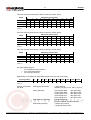
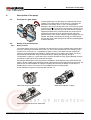
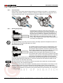
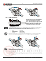
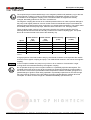
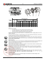
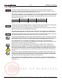
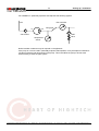
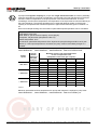
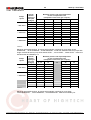
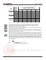
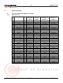
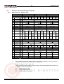
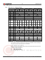
OPERATING INSTRUCTIONS
Process Gear Pumps
Series 35000 - 35350
© 2004 Scherzinger Pump Technology
Version: 1.1
Date: 17.08.2004
Author: Thomas King
Checked: Dieter Ebner
2
0.
0.
Table of contents
Table of contents
Table of contents..............................................................................................................................................2
1.
1.1.
1.2.
1.3.
1.4.
General ..............................................................................................................................................................4
Use ..................................................................................................................................................................4
Product information .........................................................................................................................................4
Pump data .......................................................................................................................................................4
Overseas offices..............................................................................................................................................6
2.1.
2.2.
2.3.
2.4.
2.5.
2.6.
2.7.
2.8.
Safety .................................................................................................................................................................7
Labelling of instructions in the operating manual ............................................................................................7
Staff qualification and training .........................................................................................................................7
Dangers of non-compliance with safety instructions .......................................................................................7
Working safely .................................................................................................................................................7
Safety instructions for the operating company ................................................................................................7
Safety instructions for servicing, maintenance, inspection and assembly work..............................................8
Unauthorised conversion and production of replacement parts......................................................................8
Improper modes of operation ..........................................................................................................................8
3.1.
3.2.
3.3.
3.4.
Transportation and interim storage................................................................................................................9
Shipment of the pumps and protection measures...........................................................................................9
Transport .........................................................................................................................................................9
Interim storage.................................................................................................................................................9
Conservation for storage after operation.........................................................................................................9
2.
3.
4.
Description of the pump ................................................................................................................................10
4.1. Principle of a gear pump ...............................................................................................................................10
4.2. Design of a process pump.............................................................................................................................10
4.2.1. Basic principle ............................................................................................................................................10
4.2.2. Flow directions............................................................................................................................................11
4.2.3. Stuffing box packing ...................................................................................................................................11
4.2.4. Single mechanical seal...............................................................................................................................11
4.2.5. Double mechanical seal .............................................................................................................................12
4.2.6. Magnetic coupling ......................................................................................................................................12
5.
Setting up / installation ..................................................................................................................................14
5.1. Information about the operating location .......................................................................................................14
5.2. First set up.....................................................................................................................................................14
5.2.1. Checks before set up starts........................................................................................................................14
5.2.2. Elastic mechanical shaft couplings ............................................................................................................14
5.2.3. Electrical drives ..........................................................................................................................................15
5.2.4. Connection pipes........................................................................................................................................15
6.
6.1.
6.2.
6.3.
6.4.
6.5.
6.6.
Start Up / shut Down ......................................................................................................................................18
Preparation for operation...............................................................................................................................18
Starting operation ..........................................................................................................................................18
Restarting after dry running...........................................................................................................................18
Monitoring......................................................................................................................................................18
Shut down......................................................................................................................................................22
Removal from the system..............................................................................................................................22
7.1.
7.2.
7.3.
7.4.
7.5.
7.6.
Maintenance....................................................................................................................................................23
General information .......................................................................................................................................23
Preparation ....................................................................................................................................................23
Coupling ........................................................................................................................................................23
Stuffing box packing ......................................................................................................................................24
Mechanical seal.............................................................................................................................................24
Disassembly and reassembly........................................................................................................................24
7.
8.
Malfunctions, causes and rectification ........................................................................................................25
Pumpenfabrik Ernst Scherzinger GmbH & Co. KG • Bregstr. 2325 • 78120 Furtwangen/ Germany • Tel.: +49 (0) 77 23 – 65 06 0 • Fax: 65 06-40 • E-Mail: [email protected]
3
9.
Table of contents
Spare parts lists..............................................................................................................................................27
9.1. Process pumps with magnetic coupling ........................................................................................................27
9.1.1. Spare parts list ...........................................................................................................................................27
9.1.2. Exploded view ............................................................................................................................................28
9.2. Stainless steel and Hastelloy foot pumps .....................................................................................................29
9.2.1. Spare parts list – Stainless steel ................................................................................................................29
9.2.2. Spare parts list - Hastelloy C4 Pumps ......................................................................................................30
9.2.3. Exploded view ............................................................................................................................................31
Cearance Certificate .................................................................................................................................................32
Declaration of Conformity ATEX 95 ........................................................................................................................33
Declaration of Conformity (Machinery Directive) ..................................................................................................34
Manufacturer's Declaration of Conformity.............................................................................................................35
Pumpenfabrik Ernst Scherzinger GmbH & Co. KG • Bregstr. 2325 • 78120 Furtwangen/ Germany • Tel.: +49 (0) 77 23 – 65 06 0 • Fax: 65 06-40 • E-Mail: [email protected]
4
1.
General
General
This operating manual contains basic information for the pumps specified in Section 1.3, which
must be complied with during installation, operation, servicing and maintenance. It is therefore
essential that this operating manual is read prior to installation and commissioning by the fitters and
the responsible technicians/operators, and must always be available at the operating location of the
machine.
In addition to the operating manual for the pump, the operating manual for the drive must also be
available and must have been read and understood.
1.1.
Use
1800
207
2004
35100 ZMKSC/M1.5
The process pumps described in this operating manual are
suitable for pumping lubricating and non-lubricating liquids that
do not have a corrosive or aggressive effect on the pump
materials used (Section 1.3). Any liquid to be pumped is
hereinafter referred to simply as the "liquid".
If you require further information that is beyond the scope of this operating manual, please contact
Scherzinger Pump Technology. If you require help, please specify precisely the pump type and
series number for which you require the information. The pump type (Typ), year of manufacture (Bj)
and serial number (Nr.) can be found on the name plate.
1.2.
Product information
This operating manual applies to pumps of types 35000, 35100, 35300, 35050, 35150, 35350,
35000..MK, 35100..MK, 35300..MK, 35050..MK, 35150..MK and 35350..MK with and without motor
from year of manufacture 2003, manufactured by Ernst Scherzinger GmbH & Co KG, 78120
Furtwangen, Germany.
The pumps are numbered consecutively. The title page of this operating manual displays the issue
date and the operating manual edition.
The motor pumps described in this operating manual conform to the applicable EU standards and
are permitted to bear the CE mark.
1.3.
Pump data
Max. differential pressure increase
Max. system pressure (pressure side)
Max. negative suction pressure
Max. pressure in heating jacket
10 bars
16 bars
-0.4 bar
25 bars
Operating temperature
-30 to 200 °C with W88 gears
-10 to 50°C with PTFE gears
Viscosity range
Range of speed
1.0 to 20,000 mPas (mm2/s)
0 to 1800 1/min
Noise level
Dimensions
< 75 dB(A),
Speed 1750 1/min
Operating pressure 2 bars;
Operating temperature 20°C;
Pump liquid 1 mm²/s;
non-lubricating
see appropriate data sheets
Pumpenfabrik Ernst Scherzinger GmbH & Co. KG • Bregstr. 2325 • 78120 Furtwangen/ Germany • Tel.: +49 (0) 77 23 – 65 06 0 • Fax: 65 06-40 • E-Mail: [email protected]
5
General
Flow rate of pump series 35000 / 35050 in litres per minute (l/min)
Differential pressure (bar)
Speed
0
1
2
3
4
5
6
7
400 1/min
4.7
4.2
3.7
3.2
2.7
2.2
1.7
1.2
8
9
10
690 1/min
8.1
7.6
7.1
6.6
6.1
5.6
5.1
4.6
4.1
3.6
3.1
930 1/min
11
10.5
10
9.5
9
8.5
8
1400 1/min
16.5
16
15.5
15
14.5
14
13.5
7.5
7
6.5
6
13
12.5
12
11.5
9
10
Table 1.1
Flow rate of pump series 35100 / 35150 in litres per minute (l/min)
Differential pressure (bar)
Speed
0
1
2
3
4
5
6
7
8
400 1/min
10.9
10.2
9.5
8.8
8.1
7.4
6.7
6
5.3
4.6
3.9
690 1/min
18.7
17
17.3
16.6
15.9
15.2
14.5
13.8
13.1
12.4
11.7
930 1/min
25.2
24.5
23.8
23.1
22.4
21.7
21
20.3
19.6
18.9
18.2
1400 1/min
38
37.3
36.6
35.9
35.2
34.5
33.8
33.1
32.4
31.7
31
9
10
Table 1.2
Flow rate of pump series 35300 / 35350 in litres per minute (l/min)
Differential pressure (bar)
Speed
0
1
2
3
4
5
6
7
400 1/min
8
25
23
21
19
17
15
13
11
9
7
5
690 1/min
43
41
39
37
35
33
31
29
27
25
23
930 1/min
58
56
54
52
50
48
46
44
42
40
38
1400 1/min
87
85
83
81
79
77
75
73
71
69
67
Table 1.3
the above tables apply for
•
•
•
0 bar negative suction pressure
20°C liquid temperature
5mm²/s liquid viscosity
Relationship of the maximum permissible speed to the viscosity of the liquid
Viscosity (mPas)
Max. speed (1/min)
1
3
10
30
100
300 1,000 3,000 10,000 30,000 100,000
1800 1800 1800 1800 1800 1800 1800 1000
350
140
20
Table 1.4
Parts in contact with
the liquid
Casing parts and shafts
1.4581 (SS316)
Hastelloy C4 only in conj. with c), d) or e)
Gears optionally
a) Drive gear W88
b) Drive gear W88
c) Drive gear PTFE
d) Drive gear HC4
e) Drive gear HC4
Shaft bearings optionally
f) Graphite bearing
g) Silicon carbide / tungsten carbide
Shaft seals optionally
• Stuffing box packing
• Single mechanical seal
Idler gear W88
Idler gear PTFE
Idler gear PTFE
Idler gear HC4
Idler gear PTFE
Pumpenfabrik Ernst Scherzinger GmbH & Co. KG • Bregstr. 2325 • 78120 Furtwangen/ Germany • Tel.: +49 (0) 77 23 – 65 06 0 • Fax: 65 06-40 • E-Mail: [email protected]
6
General
• Double mechanical seal
• Magnetic coupling only in conj. with g)
Pump media
See resistance list for the materials mentioned above
Drive
Foot pumps are supplied without electrical drives.
Motor-driven pumps (with magnetic coupling) and foot pumps, mounted on
a base plate, can be fitted with almost any commercially available standard
motor (230V single phase, 400V three phase, Ex motors, 50/60Hz).
In the event of one or more of the critical values specified in this section being exceeded, ask the
manufacturer whether he can approve these operating conditions. If not, then the pump must be
modified to suit the application, otherwise the pump, or the system into which the pump is
integrated, may become damaged or destroyed.
1.4.
Overseas offices
A list of addresses showing our offices worldwide is available. This can be requested from the
manufacturer or found on the Internet at www.scherzinger.de. For the most part, these are sales
branches, although some also carry out repairs and servicing, but the majority of this work is
implemented at the main factory in Furtwangen.
Pumpenfabrik Ernst Scherzinger GmbH & Co. KG • Bregstr. 2325 • 78120 Furtwangen/ Germany • Tel.: +49 (0) 77 23 – 65 06 0 • Fax: 65 06-40 • E-Mail: [email protected]
7
2.
Safety
Safety
Comply with the general safety instructions listed in this Safety section and also with the special
safety instructions listed under the other main sections.
2.1.
Labelling of instructions in the operating manual
The safety instructions contained in this operating manual that may create danger if not complied
with are specially labelled as follows
Non-compliance poses danger to life and limb.
Non-compliance poses danger of electrical shock.
These instructions must be complied with at all times for explosion protection.
WARNING
Non-compliance poses a risk to the machines.
Be aware of the name plate mounted directly on the pump and always maintain it in a fully legible
condition.
2.2.
Staff qualification and training
The operational, servicing, maintenance and assembly staff must have the necessary qualifications
to carry out these tasks. The area of responsibility, duties and supervision of the staff must be
carefully controlled by the operating company. In the event that the personnel do not possess the
necessary skills and knowledge, then they are to be trained and instructed accordingly.
Furthermore, the operating company must ensure that the contents of the operating manual are
understood fully by the personnel.
2.3.
Dangers of non-compliance with safety instructions
Disregarding safety instructions can pose a risk to life and limb, the environment and the pump
itself. Disregarding safety instructions may invalidate any claims for compensation.
In particular, for example, non-compliance may result in danger of the following:
•
•
•
•
2.4.
Failure of important functions of the pump
Failure of the specified methods for servicing and maintenance
Danger to persons by electrical, mechanical and chemical effects
Danger to the environment caused by the leaking of hazardous substances
Working safely
The safety instructions specified in this operating manual, existing national regulations on the
prevention of accidents and any other internal working, operating and safety regulations issued by
the operating company are to be complied with.
2.5.
Safety instructions for the operating company
Hot or cold parts representing a danger are to be designed in such a way as to prevent accidental
contact.
Pumpenfabrik Ernst Scherzinger GmbH & Co. KG • Bregstr. 2325 • 78120 Furtwangen/ Germany • Tel.: +49 (0) 77 23 – 65 06 0 • Fax: 65 06-40 • E-Mail: [email protected]
8
Safety
Leakages of hazardous substances being handled (e.g. explosive, toxic or hot materials) must be
conducted away so that no danger to persons or the environment arises. Legal regulations are to
be observed.
Dangers from electrical energy are to be eliminated (for details on this refer, e.g., to the VDE and
local power company regulations).
2.6.
Safety instructions for servicing, maintenance, inspection and assembly work
The operating company shall ensure that all servicing, maintenance and assembly work is carried
out by authorised and qualified specialist personnel who are sufficiently informed as a result of
thoroughly studying the operating manual.
•
•
•
•
2.7.
Work on the pump is only to be carried out when the pump is at a standstill.
Pumps or pumping systems handling fluids that are detrimental to health must be
decontaminated.
Upon completion of the work, all safety and protective devices must immediately be
refitted and made operational.
The points listed in the section on Starting operation must be observed before restarting.
Unauthorised conversion and production of replacement parts
Conversion or modification of the pumps shall only be permitted following consultation with the
manufacturer. Original replacement parts and accessories approved by the manufacturer have a
safety role. The manufacturer could refuse liability for any consequences arising from the use of
other parts.
2.8.
Improper modes of operation
The operational safety of the machine supplied is only ensured if it is used properly in accordance
with Section 1 - General - of the operating manual. The limiting values specified on the data sheet
and in Section 1.3 must not be exceeded under any circumstances.
Pumpenfabrik Ernst Scherzinger GmbH & Co. KG • Bregstr. 2325 • 78120 Furtwangen/ Germany • Tel.: +49 (0) 77 23 – 65 06 0 • Fax: 65 06-40 • E-Mail: [email protected]
9
3.
Transportation and interim storage
Transportation and interim storage
3.1.
Shipment of the pumps and protection measures
The pumps are dispatched from the factory in such a way that they are protected against shock
and impact. In addition, inlets and outlets are closed using protective plugs. This is necessary to
prevent any remaining fluid located in the pump as the residue from a test run from leaking out.
Any risk of foreign bodies getting into the unit is eliminated.
3.2.
Transport
We guarantee that the pumps are in perfect condition at the time of delivery and are dispatched in
suitable packaging. Upon receipt, you must inspect the pumps immediately for any transportation
damage. If you notice any damage, report it immediately to the carrier and Scherzinger Pump
Technology.
3.3.
Interim storage
The following points must be noted for storing the pumps:
•
•
•
•
•
3.4.
Do not store the pumps in wet or damp rooms.
Leave protective plugs screwed in or insert them yourself.
Corrosion protection measures must be implemented for metal blank parts if storage is
to be for longer than 6 months.
The storage rooms must not contain any ozone-generating devices, such as e.g.
fluorescent lights, mercury vapour lamps and high-voltage electrical devices.
It must be ensured that condensation cannot occur. The relative air humidity should be
below 65%.
Conservation for storage after operation
The pump must be prepared for storage in a way appropriate to the liquid being pumped. When
media without toxic or aggressive additives are being pumped, a brief flush with water at low speed
without differential pressure increase will suffice.
When toxic or aggressive media are being pumped however, the pump must be cleaned so as to
enable any subsequent maintenance work to be carried out without any risk to the health of the
personnel carrying out the work. Flush the pump on liquid speed with a neutralising liquid. Then
any parts that are not fully cleaned by the flushing process are to be disassembled and cleaned by
hand. Particular attention is to be paid to the magnetic coupling and the shaft seal.
Where curing media (e.g. varnish) have been pumped, in order to ensure that the pump is in good
working order for the next time it is used, complete disassembly (Section 7.4) and cleaning of the
individual parts of the pump will be necessary. For cleaning use conventional cleaning products or
solvents (see resistance). Following reassembly, the pump should once again be flushed with
water.
WARNING
Comply with regulations when handling substances hazardous to health!
Pumpenfabrik Ernst Scherzinger GmbH & Co. KG • Bregstr. 2325 • 78120 Furtwangen/ Germany • Tel.: +49 (0) 77 23 – 65 06 0 • Fax: 65 06-40 • E-Mail: [email protected]
10
4.
Description of the pump
Description of the pump
4.1.
Principle of a gear pump
The pumping effect of a gear pump is created by the contrarotation of two gears within a pump housing. The gears are
attached to two shafts, which, in turn, are supported on
bearings in the pump housing and cover. One of the two gears
is driven by means of a shaft, the second gear is driven by the
gears meshing. The opening up of the tooth spaces creates a
negative pressure which sucks the liquid into the pump and
transports it between the tooth spaces and the wall of the
pump housing. In the section where the gears engage with one
another, the liquid is squeezed out through the tooth spaces
and into the outlet. Thus the liquid can also be pumped against
a positive pressure.
4.2.
4.2.1.
Design of a process pump
Basic principle
The robust design of the pump, consisting of a casing and two covers, enables rapid, simple and
economic servicing and maintenance of the unit. The covers are attached to the casing by eight
screws. Each cover has a O - ring between it and the casing. The shafts with their pressed-on
gears are supported axially and radially by sleeve bearings. The rotation of the drive unit on the
pump head is transferred if using a mechanical seal or stuffing box packing through a
compensation coupling, or, where there is the need for absolute security against leakage, through
a magnetic coupling to the drive shaft and drive gear.
Scherzinger 35000 series process pumps are available in three different pump sizes (pump size
350XX, 351XX, 353XX) with and without heating jacket and with free shaft end as a foot pump. The
gear pumps are also available as magnetic coupling versions with an adapter connection to a
suitable electric motor. This version is only available without a heating jacket.
Pump capacities are given in the pump data, Section 1.3.
35000 with single mechanical seal
35000 with magnetic coupling
35000 with mechanical seal on base plate
Pumpenfabrik Ernst Scherzinger GmbH & Co. KG • Bregstr. 2325 • 78120 Furtwangen/ Germany • Tel.: +49 (0) 77 23 – 65 06 0 • Fax: 65 06-40 • E-Mail: [email protected]
11
4.2.2.
Description of the pump
Flow directions
All the pumps in this series operate independently of the direction of rotation; i.e. the direction of
rotation is fully variable. However, a change of direction of rotation results in a changeover of the
suction and pressure sides. The following typical illustration applies for all seal types.
4.2.3.
Stuffing box packing
The Stuffing box packing is made from soft but wearresistant sealing material with good sliding properties. The
sealing ring is compressed into the space provided for it in
the pump cover by means of a tightening screw and so is
pressed against the cover and the drive shaft. This type of
seal is used mainly with higher viscosity media (>1,000
mm²/s). When it wears to the extent that the liquid leaks out,
it can simply be retightened.
Pumps with stuffing box packing cannot be used in potentially explosive atmospheres because of
the large amount of heat they generate from friction.
4.2.4.
Single mechanical seal
The installed mechanical seals function independently of the
direction of rotation and are unbalanced. Standard products
use synthetic carbon and 99.5% aluminium oxide for the seal
faces. PTFE covered FEP O rings for the stationary seals and
1.4571 stainless steel for the spring and construction
materials of the pump. Many other materials can be used.
A mechanical seal must be continuously moistened with liquid
so that dry running and the consequent destruction of the seal
faces through overheating are avoided. Some of the liquid
circulates in the pump between the shaft bearings, shaft and the sealing space and lubricates and
cools the mechanical seal located there. In normal circumstances, this internal circulation of the
liquid is sufficient for lubrication and cooling.
WARNING
Mechanical seals are not to be used in continuous operation with media with viscosities greater
than 3500 mPas in the mechanical seal area.
In the event that the pumps are installed in potentially explosive atmospheres, their safety must be
ensured by the provision of a more extensive forced circulation system. This can be done by
connecting the quench connection in the area of the seal externally to the suction side of the pump.
In addition, the temperature of the liquid on the pressure side must be monitored. The values given
in Table 6.3 apply.
Pumpenfabrik Ernst Scherzinger GmbH & Co. KG • Bregstr. 2325 • 78120 Furtwangen/ Germany • Tel.: +49 (0) 77 23 – 65 06 0 • Fax: 65 06-40 • E-Mail: [email protected]
12
4.2.5.
Description of the pump
Double mechanical seal
In the version with a double mechanical seal,
two single mechanical seals are installed back
to back. Standard products use synthetic
carbon and 99.5% aluminium oxide for the seal
faces. PTFE covered FEP O - rings for the
stationary seals and 1.4571 stainless steel for
the spring and construction materials of the
pump. Many other materials can be used.
WARNING
Always operate double mechanical seals only in conjunction with a suitable seal supply system to
ensure that there is always an adequate circulation of liquid for lubrication and cooling. The
parameters for the seal supply system must be within the following values:
•
•
•
•
Flow:
1 to 6 l/min
System pressure:
max. 16 bars
Temperature:
-30°C to 200°C
Viscosity:
max. 3500 mPas
Observe the requirements of the specification and operating manual for the seal supply system.
The connection to the seal supply system must be as shown in the following illustrations:
In potentially explosive atmospheres, the flow through the seal supply system must always be
monitored. Failure of the seal supply system leads to overheating of the seals and exceeding of the
maximum permissible surface temperature.
4.2.6.
Magnetic coupling
The magnetic coupling gives the pump a hermetic seal. In other words, the end of the rotating shaft
does not project out of the pump. Leakage caused by wear of the shaft seal cannot occur, as only a
static seal is provided.
Pumpenfabrik Ernst Scherzinger GmbH & Co. KG • Bregstr. 2325 • 78120 Furtwangen/ Germany • Tel.: +49 (0) 77 23 – 65 06 0 • Fax: 65 06-40 • E-Mail: [email protected]
13
Description of the pump
The required torque is transmitted through a non-magnetic partition wall (stationary cup) to the hub
of the magnetic coupling by means of several alternately magnetised magnets on the inner
circumference in the magnetic coupling cover. The same number of magnets are similarly
arranged, alternately polarised on the outer circumference.
The magnetic coupling also serves as an overload protection device in order to prevent damage to
the pump under higher pressures. As soon as the maximum transferable torque is exceeded, the
magnetic field is broken and the drive continues to run almost without resistance. The system starts
into a steady rattle and the pump stops, whilst the drive continues to run. Pumping ceases.
There are always eddy currents in the split case induced by the rotating magnetic field. The
following table shows the losses due to eddy currents for the various coupling types. This power
loss is all converted to heat in the area of the stationary cup.
Speed
35000 stainless
steel
(7 Nm)
35100 stainless
steel
(14 Nm)
35000 Hastelloy
(7 Nm)
35100 Hastelloy
(14 Nm)
300 1/min
27 W
54 W
15 W
31 W
600 1/min
54 W
108 W
31 W
61 W
900 1/min
82 W
163 W
46 W
92 W
1200 1/min
108 W
217 W
61 W
123 W
1500 1/min
135 W
271 W
77 W
153 W
1800 1/min
163 W
325 W
92 W
184 W
Table 4.1
A large proportion of the heat is taken away by the internal circulation of the liquid and the outside
surfaces of the magnetic coupling and pump. The residual heat remains in the area of the magnetic
coupling.
WARNING
In the uncoupled condition the pump is only to be run for a maximum of 30 seconds. Longer
running times will overheat and destroy the magnetic coupling.
Do not operate the pump in the uncoupled condition in a potentially explosive atmosphere. The
complete drive output of the motor will be converted into heat and overheat the coupling within a
few seconds. The maximum permissible surface temperature could be exceeded, giving rise to a
potential danger of ignition. When being operated in a potentially explosive area, the flow through
the pump must be monitored. If the flow falters it is highly probable that the magnetic drive has
uncoupled. The drive must be brought to a standstill immediately (see Section 6.4).
Pumpenfabrik Ernst Scherzinger GmbH & Co. KG • Bregstr. 2325 • 78120 Furtwangen/ Germany • Tel.: +49 (0) 77 23 – 65 06 0 • Fax: 65 06-40 • E-Mail: [email protected]
14
5.
Setting up / installation
Setting up / installation
5.1.
Information about the operating location
Sufficient room for maintenance and servicing works must be ensured when selecting the operating
location. It should be possible to remove and re-install the pump without difficulty.
WARNING
5.2.
5.2.1.
Do not install in aggressive atmospheres.
First set up
Checks before set up starts
You must check not only the type of protection class of the pump, but also the type of protection
class of all attached components. The name plates of the individual components are important. The
type of protection for the component with the lowest protection class always applies for the
operation in potentially explosive atmospheres.
Before starting, carry out a visual check for transport damage on the pump delivered by us (see
Section 3.2).
Then check on the basis of the following points whether the delivered pump type is suitable:
•
•
•
•
•
•
Corrosion behaviour of the liquid
Viscosity of the liquid
Liquid to be pumped
Pump performance (flow rate)
Model type and design
Direction of rotation and/or position of suction/pressure sides
If you note any differences between the pump design you require in your system and the pump
delivered by us, please contact us immediately. Do not operate the pump before checking with us.
WARNING
Screw the pumps / pump units only on to the mounts provided. The installation location must be
level. Level out any unevenness near the attachment points using suitable supports so that the four
support points are at the same level. If you do not align the pump properly it can cause stresses
that could damage the pump or motor, or at the least affect the functioning.
It is important that the set direction of rotation of the drive correctly relates to the desired pumping
direction. If the direction of rotation is changed then so will the direction of pumping. The pump
itself is designed to operate independently of the direction of rotation. This means that the pump is
not very likely to suffer damage. However, considerable damage to the system and danger to the
operating personnel could result if the pump is operated with the wrong direction of rotation.
The wrong direction of rotation could empty the pump. The resulting dry running does not constitute
proper use and must be avoided in potentially explosive atmospheres at all costs.
5.2.2.
Elastic mechanical shaft couplings
Pumps on base plates with motors are supplied with the correctly installed shaft coupling from the
factory. No adjustment is necessary for the first set up. Setting of the coupling should only be
carried out as part of or after servicing work.
The supplied coupling in accordance with EU Directive 94/9/EC is in three parts. The pump may be
used in potentially explosive atmospheres only in conjunction with the supplied coupling.
Pumpenfabrik Ernst Scherzinger GmbH & Co. KG • Bregstr. 2325 • 78120 Furtwangen/ Germany • Tel.: +49 (0) 77 23 – 65 06 0 • Fax: 65 06-40 • E-Mail: [email protected]
15
Setting up / installation
3
1
2
1
3
Dimensions [mm]
Locking
thread
Shaft
OD
d (minmax)
L
l1;
l2
E
b
s
DH
dH
D
N
G
t
19
0 - 25
66
25
16
12
2
40
18
40
-
M5
10
24
0 - 35
78
30
18
14
2
55
27
55
-
M5
10
ROTEX®
Size
General
28
0 - 40
90
35
20
15
2.5
65
30
65
-
M8
15
38
38 - 45
164
70
24
18
3
80
38
78
62
M8
15
Table 5.1
Mounting the coupling:
•
•
•
Push the hubs [1] on to the shafts of the drive and the pump.
Set the E-dimension by axially moving the hubs on the shafts.
Secure the hubs by tightening the set screws [3] DIN 916.
Ensure, when mounting, that the E-dimension is maintained so that the coupling sleeve can move
axially in operation.
Ensure that sufficient distance is retained axially to the fixed components of the pump, motor and
coupling guard. We recommend a minimum distance of 5 mm.
If the use is in potentially explosive atmospheres, the screws and set screws used to hold the hub
must be additionally secured against self-loosening, e.g. by bonding with Loctite (liquid strength) or
similar means of thread locking.
5.2.3.
Electrical drives
When mounting the motor do not introduce any insulating elements between the pump adapter and
the motor. The threaded connection between the pump and motor must be made from
electroconductive material (e.g. steel).
Never install a motor pump in a constricted installation location without sufficient ventilation as the
motor may be poorly cooled and could overheat.
The electrical connection of the motors must be implemented in accordance with the guidelines
issued by the VDE and the local power supply company. The operating manual supplied with the
motors must also be complied with.
Earth the motor using the terminal provided.
To achieve the highest possible torque, particularly under heavy motor loads, three phase motors
should be connected in a delta circuit (check available mains voltage).
5.2.4.
Connection pipes
Prior to connecting the suction and pressure pipes, check that the connection flanges of the
pipework match those of the pump.
Pumpenfabrik Ernst Scherzinger GmbH & Co. KG • Bregstr. 2325 • 78120 Furtwangen/ Germany • Tel.: +49 (0) 77 23 – 65 06 0 • Fax: 65 06-40 • E-Mail: [email protected]
16
WARNING
Setting up / installation
No stress or torque shall be exerted on the pump from the connection pipes and it may be
necessary to support the connection pipes directly in front of the pump ports. Similarly, no force
arising from thermal expansion shall be exerted on the pump.
The connection pipelines must be of adequate size. They shall not be smaller than the nominal size
of the pump connections. On the suction side, one nominal size bigger than the nominal size of the
suction connection on the pump is recommended. The approximate values for the maximum flow
velocities in the pipes are:
up to 200 mm²/s
up to 600 mm²/s
up to 2000 mm²/s
Suction pipe
1.5m/s
0.5m/s
0.2m/s
Pressure pipe
3.0m/s
1.0m/s
0.5m/s
Table 5.2
WARNING
To protect the pump from damage caused by solids in the liquid, we recommend a 50-micron filter
in the suction piping. Be sure the filter does not cause a serious pressure drop.
Suction piping should be as straight and direct as possible to the pump with a minimum number of
elbows. We recommend using long radius elbow type.
The suction pipe should have a continuous rise to the pump. If it is necessary to install the piping
rising and descending, there must be a provision to purge air at the highest points of the piping.
WARNING
Once the pipes have been fitted, check that they are free from deposits, swarf or similar impurities,
as otherwise damage to the pump may result when the unit is put into operation.
Ensure that all pipes, fittings and screw joints are perfectly sealed. If this is not the case, gas may
enter the pump on the suction side. The pump will no longer suck properly. The liquid may escape
on the pressure side. Dry running may lead to heat build-up or spark generation in the pump.
If a suction height of 3 m is reached, the installation of a check valve in the suction pipe is
recommended. The valve ensures that no liquid flows back through the pump and that the suction
pipe does not empty when the pump is switched off.
Gear pumps must not be operated against a closed valve or a system that is closed on the
discharge side, as this could lead to the build up of hazardous pressure rise. A pressure relief
device must always be installed (e.g. a pressure relief valve). If it can happen that the pump must
work against a closed system, a relief valve must be installed directly downstream of the pump on
the discharge side. The return pipe must not be directly fed to the suction side but must return to
the tank.
If the pump is used in a potentially explosive atmosphere, you should install a check valve in the
suction line immediately upstream of the pump, which will prevent the pump from emptying during
standstills and dry running upon starting up again. The pipe directly downstream of the pressure
side should be laid with a rising gradient, at least for a short distance.
Please note that with this installation situation, the inlet pressure is equal to the outlet pressure
when the pump is at a standstill. Please note the max. system pressure on the pressure side (refer
to Section 1.3).
Pumpenfabrik Ernst Scherzinger GmbH & Co. KG • Bregstr. 2325 • 78120 Furtwangen/ Germany • Tel.: +49 (0) 77 23 – 65 06 0 • Fax: 65 06-40 • E-Mail: [email protected]
17
Setting up / installation
For installation in potentially explosive atmospheres the following applies:
inlet
flow controller
rising pipe
in
out
check valve
reliefvalve
temperaturesensor
Noise insulation measures may be required on the pipework.
If the pump is not to be used in potentially explosive atmospheres, it may be helpful to install shutoff valves upstream and downstream of the pump. This would allow the pump to be removed
without having to drain the pipe system.
Pumpenfabrik Ernst Scherzinger GmbH & Co. KG • Bregstr. 2325 • 78120 Furtwangen/ Germany • Tel.: +49 (0) 77 23 – 65 06 0 • Fax: 65 06-40 • E-Mail: [email protected]
18
6.
Start Up / shut Down
Start Up / shut Down
6.1.
Preparation for operation
Following complete installation, check the pump and peripherals again using the following list of
questions:
•
•
•
•
•
•
•
•
6.2.
Can the pump be rotated by hand (e.g. when turning the motor fan)?
Have you connected the suction and pressure sides correctly?
Does the drive direction of rotation agree with that of the pump?
Are the butterfly valves, gate valves and valves in their correct positions?
Has the pipe system been checked for leaks?
Is it possible to stop the pump by an emergency switch in case of malfunction?
Is there sufficient and the correct liquid in the tank?
If the temperature difference between pump and liquid is greater than 50°C, the pump
must be tempered before starting!
Starting operation
•
•
Clean the pump and pipe system if necessary.
In order not to contaminate the liquid, it is recommended that a flushing process of at
least 5 minutes is implemented with the liquid and at the appropriate pump speed to
remove all test liquid residues from the pump.
•
Dry running time should not exceed 30 seconds.
The ignition temperature of the pumped liquid must be at least 50K above the maximum
permissible surface temperature.
If the pump is used in potentially explosive atmospheres, it must not run dry. The pump and all
pipes must be filled with liquid before starting.
WARNING
Open all slides and butterfly valves in the pipe system. The pump must not pump from a closed
suction pipe or against a closed system!
Pre-heat pumps with the heating jacket before start up. The pre-heating time depends on the
material properties of the pumped liquid. The pre-heating must always ensure that all the parts of
the pump to be in contact with the liquid have reached the operating temperature. We recommend
a pre-heating time of 2 to 3 hours.
6.3.
Restarting after dry running
After a brief period of dry running (it is assumed that the pump is still undamaged), you must
ensure that the pump is allowed to cool to a temperature below its permissible surface
temperature. The pump and pipelines must be completely deaerated.
Re-starting after a longer period of dry running does not constitute proper use. The pump must be
removed from the system, checked for damage and any damaged parts must be replaced.
The pump may only be operated again after it has been completely filled and the electrical earth
restored.
6.4.
WARNING
WARNING
Monitoring
We recommend, for pressure monitoring purposes, that a pressure monitoring device is installed
on the suction side (depending on the operating conditions – inlet pressure or vacuum) and that a
pressure measuring device that meets the operating requirements is installed on the pressure side.
Stay within the parameters of the pump data given in Section 1.3, otherwise the pump may become
damaged.
The liquid temperature should be monitored on the pressure side. The pump may develop leaks or
be destroyed if the permissible temperature range of the seal materials is not observed (see
Section 1.3).
Pumpenfabrik Ernst Scherzinger GmbH & Co. KG • Bregstr. 2325 • 78120 Furtwangen/ Germany • Tel.: +49 (0) 77 23 – 65 06 0 • Fax: 65 06-40 • E-Mail: [email protected]
19
Start Up / shut Down
If pumps with magnetic couplings or pumps with single mechanical seals are used in potentially
explosive atmospheres, particular consideration must be paid to the heat transferred into the liquid
and the increase in temperature of the pump surface in the area of the shaft seal. To avoid
exceeding a critical surface temperature, the temperature of the liquid must be monitored directly at
the pump discharge. The surface temperature to be expected depends greatly on the thermal
capacity of the liquid and the ambient temperature. Approximate values are given in Tables 6.1 to
6.4
Here is an example showing how the maximum permissible liquid temperature can be calculated:
Pump: 35100 ZFMKSC/M1.5
Pump speed: 1450 1/min
Liquid: ethanol, specific thermal capacity: 2.43 kJ/(Kg*K)
Atmosphere: ethylene ether (temperature class T4)
Ambient temperature: 35°C
The maximum permissible temperature of the liquid at the pump discharge would be 90°C (see
Table 6.3). If this liquid temperature is exceeded, the pump must be immediately brought to a
standstill.
Maximum permissible surface temperatures for pumps with magnetic couplings for pump sizes
35000 ZFMKSC/M... , 35000 ZFMKK/M..., 35000 ZMKSC/M... made from stainless steel:
Pumps
speed
< 600 1/min
< 1200 1/min
< 1800 1/min
Maximum pressure side liquid temperature
for use in temperature class
(Temperature class of the gas or vapour)
specific
thermal
capacity of
the liquid
(kJ/kg*K)
T1, T2
T3
T4
T5
T6
<1
200°C
162 °C
97 °C
62 °C
47 °C
<2
200°C
165 °C
100 °C
65 °C
50 °C
<4
200°C
167 °C
102 °C
67 °C
52 °C
>4
200°C
168 °C
103 °C
68 °C
53 °C
<1
200°C
154 °C
89 °C
54 °C
39 °C
<2
200°C
159 °C
94 °C
59 °C
44 °C
<4
200°C
164 °C
99 °C
64 °C
49 °C
>4
200°C
167 °C
102 °C
67 °C
52 °C
<1
200°C
138 °C
73 °C
38 °C
23 °C
<2
200°C
149 °C
84 °C
49 °C
34 °C
<4
200°C
158 °C
93 °C
58 °C
43 °C
>4
200°C
164 °C
99 °C
64 °C
49 °C
Table 6.1
Maximum permissible surface temperatures for pumps with magnetic couplings for pump sizes
35000 ZFMKSC/M... , 35000 ZFMKK/M..., 35000 ZMKSC/M... made from Hastelloy C4:
Pumpenfabrik Ernst Scherzinger GmbH & Co. KG • Bregstr. 2325 • 78120 Furtwangen/ Germany • Tel.: +49 (0) 77 23 – 65 06 0 • Fax: 65 06-40 • E-Mail: [email protected]
20
Pumps
speed
< 600 1/min
< 1200 1/min
< 1800 1/min
Start Up / shut Down
specific
thermal
capacity of
the liquid
(kJ/kg*K)
T1, T2
T3
T4
T5
T6
<1
200°C
166 °C
101 °C
66 °C
51 °C
<2
200°C
167 °C
102 °C
67 °C
52 °C
<4
200°C
168 °C
103 °C
68 °C
53 °C
Maximum pressure side liquid temperature
for use in temperature class
(Temperature class of the gas or vapour)
>4
200°C
169 °C
104 °C
69 °C
54 °C
<1
200°C
162 °C
97 °C
62 °C
47 °C
<2
200°C
165 °C
100 °C
65 °C
50 °C
<4
200°C
167 °C
102 °C
67 °C
52 °C
>4
200°C
168 °C
103 °C
68 °C
53 °C
<1
200°C
154 °C
89 °C
54 °C
39 °C
<2
200°C
159 °C
94 °C
59 °C
44 °C
<4
200°C
164 °C
99 °C
64 °C
49 °C
>4
200°C
167 °C
102 °C
67 °C
52 °C
Table 6.2
Maximum permissible surface for pumps with magnetic couplings for pump sizes 35100
ZFMKSC/M... , 35100 ZFMKK/M..., 35100 ZMKSC/M... made from stainless steel and pumps with
single mechanical seal for pump sizes 350x0 GLRD ..., 351x0 GLRD..., 353x0 GLRD... made from
stainless steel and Hastelloy C4:
Pumps
speed
< 600 1/min
< 1200 1/min
< 1800 1/min
specific
thermal
capacity of
the liquid
(kJ/kg*K)
T1, T2
T3
T4
T5
T6
<1
200°C
154 °C
89 °C
54 °C
39 °C
<2
200°C
159 °C
94 °C
59 °C
44 °C
<4
200°C
164 °C
99 °C
64 °C
49 °C
Maximum pressure side liquid temperature
for use in temperature class
(Temperature class of the gas or vapour)
>4
200°C
167 °C
102 °C
67 °C
52 °C
<1
200°C
138 °C
73 °C
38 °C
23 °C
<2
200°C
149 °C
84 °C
49 °C
34 °C
<4
200°C
158 °C
93 °C
58 °C
43 °C
>4
200°C
164 °C
99 °C
64 °C
49 °C
<1
200°C
105 °C
40 °C
5 °C
-10 °C
<2
200°C
127 °C
62 °C
27 °C
12 °C
<4
200°C
145 °C
80 °C
45 °C
30 °C
>4
200°C
157 °C
92 °C
57 °C
42 °C
Table 6.3
Maximum permissible surface for pumps with magnetic couplings for pump sizes
35100 ZFMKSC/M... , 35100 ZFMKK/M..., 35100 ZMKSC/M... made from Hastelloy C4:
Pumpenfabrik Ernst Scherzinger GmbH & Co. KG • Bregstr. 2325 • 78120 Furtwangen/ Germany • Tel.: +49 (0) 77 23 – 65 06 0 • Fax: 65 06-40 • E-Mail: [email protected]
21
Pumps
speed
Start Up / shut Down
specific
thermal
capacity of
the liquid
(kJ/kg*K)
T1, T2
T3
<1
200°C
<2
200°C
<4
200°C
< 600 1/min
< 1200 1/min
< 1800 1/min
Maximum pressure side liquid temperature
for use in temperature class
(Temperature class of the gas or vapour)
T4
T5
T6
162 °C
97 °C
62 °C
47 °C
165 °C
100 °C
65 °C
50 °C
167 °C
102 °C
67 °C
52 °C
>4
200°C
168 °C
103 °C
68 °C
53 °C
<1
200°C
154 °C
89 °C
54 °C
39 °C
<2
200°C
159 °C
94 °C
59 °C
44 °C
<4
200°C
164 °C
99 °C
64 °C
49 °C
>4
200°C
167 °C
102 °C
67 °C
52 °C
<1
200°C
138 °C
73 °C
38 °C
23 °C
<2
200°C
149 °C
84 °C
49 °C
34 °C
<4
200°C
158 °C
93 °C
58 °C
43 °C
>4
200°C
164 °C
99 °C
64 °C
49 °C
Table 6.4
If you are using a pump with a single or double mechanical seal, the discharge side liquid
temperature must be at least 30°C less than the permissible surface temperature of the
temperature class in which the pump is installed.
Liquid temperatures above the permissible temperatures for the materials (see Section 1.3) does
not constitute proper use and must be avoided.
Remove accumulated dust from the surface of the pump, drive and connected pipes regularly to
avoid the formation of dust nests, which could act as an ignition source. The cleaning frequency is
determined by the rate of dust accumulation.
Monitor the noise level of the pump. In the event of grinding sounds, turn the pump off immediately.
Inspect the pump for wear. Metallic parts rubbing together can cause overheating or sparking.
If the pump is used in a potentially explosive atmosphere, a flow controller must be installed directly
downstream of the pump. The flow controller must not create a noticeable back pressure in case of
damage. A float or flat-type flow meter is preferred. If the delivery rate of the gear pump falls to
20% of the theoretical flow rate, the pump must be stopped immediately. This is an obvious sign of
wear. The pump must be stopped immediately. The value of 20% of the theoretical flow rate can be
calculated as follows:
Q theo20 =
Qtheo20:
n:
vgP:
v gP ⋅ n
5000
20% of the theoretical flow rate in lpm
Drive speed in rpm
Pump displacement (see following table)
Pumpenfabrik Ernst Scherzinger GmbH & Co. KG • Bregstr. 2325 • 78120 Furtwangen/ Germany • Tel.: +49 (0) 77 23 – 65 06 0 • Fax: 65 06-40 • E-Mail: [email protected]
22
Displacement vgP
Start Up / shut Down
Volumetric flow rate (min. always to be achieved)
e.g. at the following speeds:
730 1/min
970 1/min
1450 1/min
11.2 cm³/U
1.3 l/min
3.2 l/min
3.3 l/min
Pump size
35100/35150
24.8 cm³/U
3.6 l/min
4.8 l/min
7.2 l/min
Pump size
35300/35350
60.7 cm³/U
8.8 l/min
11.8 l/min
17.6 l/min
Pump size
35000/35050
Table 6.5
Take note of the advice relating to seals in Sections 4.2.3 to 4.2.6.
6.5.
Shut down
Make sure that there is no potentially explosive atmosphere.
When liquids which could be hazardous to health have been pumped, flush the pump thoroughly
with a suitable cleaning or neutralising solution (do not use a corrosive liquid) for several minutes.
After any cleaning has been completed, the pump should be flushed again with water.
Switch off the drive unit.
Shut off the heating circuit for the heating jacket.
If present, close the shut-off valves upstream and downstream of the pump. Close the shut-off
valves only, if the pump will stand still for a longer period of time (for automatic equipment, only
when the whole system is taken out of operation).
If the standstill is to be a long one, drain the pump completely.
6.6.
Removal from the system
Make sure that the steps described in Section 6.5 have been carried out.
•
•
•
•
•
•
Check that there is no pressure at the inlet and outlet or in the heating circuit.
Drain the pump completely.
Drain the heating circuit completely.
Disconnect the drive unit from the electricity supply.
Remove the connections to the pump and the heating jacket.
If necessary, clean the pump as described in Section 3.4.
Pumpenfabrik Ernst Scherzinger GmbH & Co. KG • Bregstr. 2325 • 78120 Furtwangen/ Germany • Tel.: +49 (0) 77 23 – 65 06 0 • Fax: 65 06-40 • E-Mail: [email protected]
23
7.
Maintenance
Maintenance
7.1.
General information
Regular servicing as described in Section 7.3 must be carried out. Servicing is also required when
•
•
•
•
•
•
the pump is to be stored,
the pump is to be unused for an indeterminate period,
the pump no longer meets the key data described in Section 1.3,
a different liquid is to be conveyed,
leakage occurs in the pump,
a malfunction as described in Section 8 occurs.
We recommend that repair work is to be carried out by the manufacturer at the factory. Ensure that
the pump is flushed with a safe liquid before maintenance work is carried out (refer to Section 3.4).
The accompanying clearance certificate must be filled out completely before shipping the pump.
Defective pumps without clearance certificates will not be accepted.
7.2.
Preparation
Ensure that the entire drive train is secured against unintended start-up before mounting or
servicing the pump. Serious injury can be caused by rotating parts. It is essential to read and
comply with the safety instructions below.
Switch off the drive unit.
Secure the drive unit against unintended start-up, e.g. by mounting warning signs on the switch-on
point, or removing the fuse from the power supply.
Do not reach into the working area of the coupling when it is still in operation.
Ensure that the pump is flushed with a safe liquid before any servicing work. If the pump has been
operated with a liquid hazardous to health, servicing must be implemented with appropriate safety
measures.
7.3.
Coupling
A checking of the circumferential backlash and a visual check of the flexible spider must be
effected after 2,000 operating hours for the first time, after 3 months at the latest. If you note an
unconsiderable or no wear at the spider after this first inspection, the further inspections can be
effected, in case of the same operating parameters, respectively after 4,000 operating hours or
after 12 months at the latest.
If you note a considerable wear during the first inspection, so that a change of the spider would be
recommended, please find out the cause according to the table „Breakdowns“, as far as possible.
The maintenance intervals must be adjusted according to the changed operating parameters.
feeler gauge
B = new state
X = wear
spider
hub 1
hub 2
Checking the limit of wear
Wear of the spider
The elastic spider must be replaced when X exceeds the figures in table 7.1.
Pumpenfabrik Ernst Scherzinger GmbH & Co. KG • Bregstr. 2325 • 78120 Furtwangen/ Germany • Tel.: +49 (0) 77 23 – 65 06 0 • Fax: 65 06-40 • E-Mail: [email protected]
24
Maintenance
When the replacement limits will be reached depends on the operating conditions and operating
parameters.
ROTEX®
Size
Wear limits (friction)
Xmax. [mm]
19
3
24
3
28
3
38
3
Table 7.1
7.4.
Stuffing box packing
If a pump with a stuffing box packing type of seal develops a leak during operation, the stuffing box
packing can simply be recompressed by tightening the tightening screw. Just turn the tightening
screw clockwise with an open spanner until the fluid stops leaking out.
WARNING
Tighten the tightening screw no further than is required to stop the leak of fluid. Any tighter and the
pump may overheat.
If the pump can no longer be stopped from leaking by retightening, the stuffing box packing must
be replaced. For more details refer to the servicing manual.
7.5.
Mechanical seal
When you replace the mechanical seals, you must leave the parallel pins [9] in position. If they are
not pressed in properly they can rub on the shaft and therefore present the danger of ignition.
7.6.
WARNING
Disassembly and reassembly
Particular care is to be taken to ensure that all O-rings and flat seals are replaced upon reassembly
as part of any servicing work that involves dismantling the pump. Otherwise, complete leakage
prevention cannot be guaranteed. Absolute cleanliness of the workplace is essential for this task,
as any dirt could threaten the proper functioning of the pump.
Grease the cover screws (16 No.) when assembling the pump, otherwise they could become stuck
in the threads and make disassembly more difficult next time.
We recommend that servicing is always carried out in the manufacturers factory. If you wish to
service or repair the pump yourself, please observe the provisions of the relevant servicing
manuals.
Pumpenfabrik Ernst Scherzinger GmbH & Co. KG • Bregstr. 2325 • 78120 Furtwangen/ Germany • Tel.: +49 (0) 77 23 – 65 06 0 • Fax: 65 06-40 • E-Mail: [email protected]
25
8.
Malfunctions, causes and rectification
Malfunctions, causes and rectification
(I)
The pump is not sucking properly
(a) Pipework incorrectly designed
Pipes that are the wrong size can have a serious negative effect on pump suction. The instructions
in Section 5.2 - Connection pipes - are to be observed.
(b) Pressure pipe is closed
If a shut-off valve is integrated on the pressure side, ensure that it is open. If there is still air in the
pressure pipe, ensure that it can be vented.
(c) Suction pipe is closed
If a shut-off valve is integrated on the suction side, ensure that it is open.
(d) Pump is worn out
If the pump no longer sucks although operating conditions remain unchanged and the suction and
pressure pipes are open, the pump probably requires maintenance.
(e) Suction pipe leaking
Ensure that the suction line is absolutely gas tight so that surrounding atmosphere cannot be
sucked in.
(II)
The pump builds up too little or no pressure
(a) Pipes closed
Where there are shut-off valves in the pipes on the pressure or suction side, ensure that these are
open.
(b) Liquid viscosity too low
The efficiency of the pump is dependent on the viscosity (consistency of the liquid). If the viscosity
(arising from the particular liquid or too high a temperature) decreases too much, this can cause a
drop in flow rate.
(c) Pump is worn out
If none of the points described above apply, or if the pump capacity falls without any change in the
operating conditions, then it is likely that the pump requires maintenance. Please contact the
manufacturer.
(d) Coupling defective
Replace damaged coupling components. A damaged coupling is always a sign of overload. Rectify
the cause of the overload.
(III)
The pump is making noises
If vibration, grinding or scratching noises can be heard, stop the drive immediately. The malfunction
must be rectified immediately. Possible causes are:
(a) Extreme wear in the pump
The pump must not be operated in this condition. The pump requires maintenance.
(b) Cavitation operation
As a result of the combination of inlet pressure, suction height and vapour pressure of the liquid,
vapour bubbles form in the suction area of the pump. These implode again on the pressure side
and lead to increased wear on the pump. This working point can be avoided by changing the
operating conditions.
(c) Coupling wear
Pumpenfabrik Ernst Scherzinger GmbH & Co. KG • Bregstr. 2325 • 78120 Furtwangen/ Germany • Tel.: +49 (0) 77 23 – 65 06 0 • Fax: 65 06-40 • E-Mail: [email protected]
26
Malfunctions, causes and rectification
Check the wear limits of the coupling, see Section 7.3. If coupling wear is too high, replace the
worn parts, as overheating can pose an ignition danger.
(d) Pump with magnetic coupling rattles
The magnetic coupling is uncoupled. Stop the drive and start it again. If the pump does not engage
again, check the operating parameters.
(IV)
The pump is getting hot
(a) It is possible that this is a normal operating mode
Please check first whether this is normal heating caused by the liquid being conveyed. After a short
time of operation, the pump surface assumes the temperature of the liquid.
(b) Grinding noises
If scratching noises can be heard, this indicates wear in the pump. The pump must not be operated
in this condition. Stop the drive immediately. A repair is urgently required.
(c) Pump is worn out
If the flow rate drops over time, but the pump is still building pressure, it is likely that wear is
present. Please contact the manufacturer regarding repairs.
(V)
Fluid is escaping from the shaft end
(a) Pump with stuffing box packing
The shaft seal has become slightly worn during operation. Adjust it in accordance with Section 7.4.
(b) Pump with single mechanical seals
A slight leakage of one drop per day is permissible. If the pump has a higher leakage rate the
mechanical seal must be replaced.
Pumpenfabrik Ernst Scherzinger GmbH & Co. KG • Bregstr. 2325 • 78120 Furtwangen/ Germany • Tel.: +49 (0) 77 23 – 65 06 0 • Fax: 65 06-40 • E-Mail: [email protected]
27
9.
Spare parts lists
Spare parts lists
9.1.
9.1.1.
Process pumps with magnetic coupling
Spare parts list
35000
ZFMKSC/M055
35100
ZMKSC/M1.1
35000
ZFMKSC/M055 HC4
35100
ZMKSC/M1.1 HC4
35000
ZFMKSC/M075
35100
ZMKSC/M1.5
35000
ZFMKSC/M075 HC4
35100
ZMKSC/M1.5 HC4
Item
Description
Number
Drawing No.
Drawing No.
Drawing No.
Drawing No.
1
Cover
1
35000-002.01
35000-002.01
35011-002.01
35011-002.01
2
Cover
1
35000-002.10
35000-002.10
35011-002.10
35011-002.10
3
Drive shaft
1
35000-005.10
35100-005.10
35011-005.10
35111-005.10
4
Idler shaft
1
35000-006.00
35100-006.00
35011-006.00
35111-006.00
5
Gear
2
35000-007.00
35100-007.00
35000-007.01/-007.02
35100-007.01/-007.02
6
Sleeve bearing
4
35000-010.02
35100-010.02
35000-010.02
35100-010.02
7
Bearing insert
4
35000-010.04
35100-010.04
35000-010.04
35100-010.04
8
Centring washer
1
35000-012.00
35000-012.00
35011-012.00
35011-012.00
9
Set screw
1
35000-024.00
35000-024.00
35011-024.00
35011-024.00
10
Flat seal
1
35000-066.00
35000-066.00
35000-066.00
35000-066.00
11
Flat seal
1
35000-066.01
35000-066.01
35000-066.01
35000-066.01
12
Adapter flange
1
35000-122.00
35000-122.00
35000-122.00
35000-122.01
13
Motor coupling hub
1
35000-125.00
35000-125.01
35000-125.00
35000-125.00
14
Mounting base plate
1
35000-139.00
N/A
35000-139.00
N/A
15.1
Stationary cup
1
35000-145.00
35000-145.00
35011-145.00
35011-145.00
15.2
Magnetic coupling hub
1
35000-124.00K
35000-124.10K
35011-124.00K
35011-124.10K
15.2
Magnetic coupling
1
35000-126.00K
35000-126.10K
35000-126.00K
35000-126.10K
16
Casing
1
35050-001.00
35050-001.00
35051-001.00
35051-001.00
17
Parallel Pin
2
701094
701094
701094
701094
18
Spring Pin
1
701228
N/A
701228
N/A
19
Hex head cap screw
4
702054
702054
702054
702054
20
Set screw
1
702220
702220
702220
702220
21
Hex head cap screw
20
702233
702233
702233
702233
22
Hex head cap screw
6
702248
702248
702248
702248
23
Headless screw
4
702261
702261
702333
702333
24
Hex head cap screw
8
702606
702606 (4x)
702606
702606 (4x)
25
Feather key
2
707060
702062
707080
707083
26
Feather key
2
707061
707061
707081
707081
27
Feather key
1
707062
707062
707083
707083
28
Feather key
2
707079
707079
707082
707082
29
Circlip
4
712043
712043
712043
712043
30
Circlip
8
712053
712053
712053
712053
31
O-ring
2
718154
718154
718154
718154
32
Motor
1
As ordered
As ordered
As ordered
As ordered
Table 9.1
Pumpenfabrik Ernst Scherzinger GmbH & Co. KG • Bregstr. 2325 • 78120 Furtwangen/ Germany • Tel.: +49 (0) 77 23 – 65 06 0 • Fax: 65 06-40 • E-Mail: [email protected]
28
9.1.2.
Spare parts lists
Exploded view
Pumpenfabrik Ernst Scherzinger GmbH & Co. KG • Bregstr. 2325 • 78120 Furtwangen/ Germany • Tel.: +49 (0) 77 23 – 65 06 0 • Fax: 65 06-40 • E-Mail: [email protected]
29
9.2.
9.2.1.
Spare parts lists
Stainless steel and Hastelloy foot pumps
Spare parts list – Stainless steel
Seal types …
Bearing types …
Item
Description
K
35000 () / 35050 ()
35100 () / 35150 ()
35300 () / 35350 ()
S
S
S
GLRD
SC
K
SC
K
GLRD
SC
K
SC
K
GLRD
SC
K
SC
No.
1
Casing ()
1
35000-001.00
35000-001.00
35300-001.00
1.1
Casing ()
1
35050-001.00K
35050-001.00K
35350-001.00K
2
Cover
1
2.1
Cover
1
35000-002.00
35000-002.00
2.2
Cover
1
35000-002.01
35000-002.01
35300-002.01
3
Drive shaft
1
35000-005.00
35000-005.00
35300-005.00
4
Idler shaft
1
35000-006.00
35000-006.00
35300-006.00
51)
Gear W
35000-007.00
35100-007.00
35300-007.00
35000-002.02
35300-002.00
35000-002.02
35300-002.02
Gear T
35000-007.01
35100-007.01
35300-007.01
Gear H
35000-007.02
35100-007.02
35300-007.02
6
Bearing insert
4
35000
010.00
35000
010.00
35100
010.00
6.1
Sleeve bearing
4
35000
010.02
35000
010.02
35100
010.02
35100
010.02
35300
010.02
35300
010.02
6.2
Bearing insert
4
35000
010.04
35000
010.04
35100
010.04
35100
010.04
35300
010.04
35300
010.04
35000-095.00
35100
010.00
35300
010.00
35000-095.00
35300
010.00
7
Cap nut
1
8
Parallel pin
2
9
Parallel pin
10
Hex head cap
screw
16
11
Plug screw
1
12
Headless screw
4
13
Sealing ring
1
14
Feather key
2
707060
707062
707064
15
Feather key
2
707061
707061
707061
16
Feather key
1
707062
707062
707064
17
Feather key
2
707079
707079
18
Mechanical seal
1
19
Stuffing box
packing
5
20
Retaining ring
1
21
O-ring
2
701094
701096
701095
701096
702233
702233
702255
702261
35300-095.00
701094
702261
702255
702261
704544
702261
702262
704544
707085
708038
708047
708038
708036 (4x)
712064
718154
702255
702262
704544
708038
708047
701096
702264
712064
718154
712065
718161
Table 9.2
1)
Gears made from different materials can be used in any combination. There must always
be 2 gears in a pump. We recommend the combinations:
2 x W / 1xW, 1xT / 2xT / 1xH, 1xT
Other combinations are possible in theory but they can seriously reduce the service life of
the pump in certain circumstances.
W:
T:
H:
Gear made from W88
Gear made from PTFE
Gear made from Hastelloy
Pumpenfabrik Ernst Scherzinger GmbH & Co. KG • Bregstr. 2325 • 78120 Furtwangen/ Germany • Tel.: +49 (0) 77 23 – 65 06 0 • Fax: 65 06-40 • E-Mail: [email protected]
30
9.2.2.
Spare parts lists
Spare parts list - Hastelloy C4 Pumps
35000 HC4 () / 35050 HC4 ()
Seal types …
S
Bearing types …
Item
Description
K
35100 HC4 () / 35150 HC4 ()
GLRD
SC
K
SC
S
K
35300 HC4 () / 35350 HC4 ()
GLRD
SC
K
S
SC
K
GLRD
SC
K
SC
No.
1
Casing ()
1
35011-001.00
35011-001.00
35311-001.00
1.1
Casing ()
1
35051-001.00K
35051-001.00K
35351-001.00K
2
Cover
1
2.1
Cover
1
35011-002.00
35011-002.00
2.2
Cover
1
35011-002.01
35011-002.01
35311-002.01
3
Drive shaft
1
35011-005.00
35011-005.00
35311-005.00
4
Idler shaft
1
35011-006.00
35011-006.00
35311-006.00
51)
Gear W
35000-007.00
35100-007.00
35300-007.00
35011-002.02
35311-002.00
35011-002.02
35311-002.02
Gear T
35000-007.01
35100-007.01
35300-007.01
Gear H
35000-007.02
35100-007.02
35300-007.02
6
Bearing insert
4
35000
010.00
35000
010.00
35100
010.00
6.1
Sleeve
Bearing
4
35000
010.02
35000
010.02
35100
010.02
35100
010.02
35300
010.02
35300
010.02
6.2
Bearing insert
4
35000
010.04
35000
010.04
35100
010.04
35100
010.04
35300
010.04
35300
010.04
35011-095.00
35100
010.00
35300
010.00
35011-095.00
35300
010.00
7
Cap Nut
1
8
Parallel pin
2
9
Parallel pin
10
Hex head cap
screw
16
11
Plug screw
1
12
Headless
screw
4
13
Sealing ring
1
14
Feather key
2
707080
707083
on request
15
Feather key
2
707081
707081
on request
16
Feather key
1
707083
707083
on request
17
Feather key
2
707082
707082
18
Mechanical
seal
1
19
Stuffing box
packing
5
20
Retaining ring
1
21
O-ring
2
701094
701096
701095
701096
702233
702233
702394
702333
35311-095.00
701094
702333
702394
702333
704544
702333
on
request
704544
on request
708147
708047
on request
708036 (4x)
N/A
718154
702394
on
request
704544
708147
708047
701096
702264
N/A
718154
N/A
718161
Table 9.3
1)
Gears made from different materials can be used in any combination. There must always
be 2 gears in a pump. We recommend the combinations:
2 x W / 1xW, 1xT / 2xT / 1xH, 1xT
Other combinations are possible in theory but they can seriously reduce the service life of
the pump in certain circumstances.
W:
T:
H:
Gear made from W88
Gear made from PTFE
Gear made from Hastelloy
Pumpenfabrik Ernst Scherzinger GmbH & Co. KG • Bregstr. 2325 • 78120 Furtwangen/ Germany • Tel.: +49 (0) 77 23 – 65 06 0 • Fax: 65 06-40 • E-Mail: [email protected]
31
9.2.3.
Spare parts lists
Exploded view
Foot pump with Stuffing box packing and graphite sleeve bearings (35xxx S K)
Foot pump with mechanical seal and ceramic sleeve bearings (35xxx GLRD SC)
Pumpenfabrik Ernst Scherzinger GmbH & Co. KG • Bregstr. 2325 • 78120 Furtwangen/ Germany • Tel.: +49 (0) 77 23 – 65 06 0 • Fax: 65 06-40 • E-Mail: [email protected]
32
Cearance Certificate
Cearance Certificate
The pump and accessories sent to us for inspection and/or repair accompanied by this clearance certificate,
Type
Pump number
Delivered
Reason for repair
Reason (continued)
O have not been used with hazardous liquids
O have come into contact with liquids requiring special labelling or with liquids polluted by hazardous
substances.
Specify last liquid pumped
Prior to dispatch / delivery, the pump was emptied carefully and cleaned thoroughly inside and out.
The cleaning process was conducted in accordance with the appropriate operating manual.
O Special safety precautions are not necessary for subsequent handling.
O The following safety precautions are necessary with regard to flushing liquid and disposal:
We confirm that the details given above are correct and complete and that the goods were dispatched in
accordance with applicable legal provisions.
Company
Name
Street
Position
City
Phone
Country
Fax
Date
Company stamp / signature
For safety reasons pumps supplied without this completed safety data sheet cannot be inspected or re-paired.
Pumpenfabrik Ernst Scherzinger GmbH & Co. KG • Bregstr. 2325 • 78120 Furtwangen/ Germany • Tel.: +49 (0) 77 23 – 65 06 0 • Fax: 65 06-40 • E-Mail: [email protected]
33
Declaration of Conformity ATEX 95
Declaration of Conformity ATEX 95
with the provisions of Directive 94/9/EC
In accordance with EU Directive 94/9/EC dated 23 March 1994, and the legislation arising from its
implementation, the manufacturer:
Pumpenfabrik Ernst Scherzinger GmbH & Co. KG
Bregstraße 23-25
D – 78120 Furtwangen
declares that the explosion protected product, described in the operating and safety instructions:
Type:
Process gear pump
Series:
35000 - 35300 ZFMK...
35000 - 35350 GLRD ...
35000 - 35300 ZMK...
35000 - 35350 DGLRD ...
is a device in the sense of Article 1, (3) a) of Directive 94/9/EC, and complies with the essential safety and
health requirements as per Appendix II of Directive 94/9/EC and the following harmonised directives:
DIN EN 13463-1
E DIN EN 13463-5
The specified pump type falls into the explosion protection design classification "c". An ignition hazard
assessment is available. The pump carries the identification:
II 2 G c X
The technical documentation, in compliance with Article 8, (1) b) ii) of the directive 94/9/EC, in combination with
Appendix VIII, has been deposited with the following named body:
Deutsche Montan Technologie GmbH
Dinnendahlstraße 9
D - 44809 Bochum
Furtwangen, 29 September 2003
(Dipl.-Ing. Erich Willimsky)
Managing Director
Pumpenfabrik Ernst Scherzinger GmbH & Co. KG • Bregstr. 2325 • 78120 Furtwangen/ Germany • Tel.: +49 (0) 77 23 – 65 06 0 • Fax: 65 06-40 • E-Mail: [email protected]
34
Declaration of Conformity (Machinery Directive)
Declaration of Conformity (Machinery Directive)
with the Provisions of Directive 98/37/EC
In accordance with EU Directive 98/37/EC, Appendix II, dated 22 June 1998, the manufacturer:
Pumpenfabrik Ernst Scherzinger GmbH & Co. KG
Bregstraße 23-25
D – 78120 Furtwangen
declares that the pumps:
Type:
Process gear pump
Series:
35000 - 35350 with drive
is supplied with an electric drive unit and therefore complies with the provisions of Directive 98/37/EC,
Appendix 1, No. 1.
Applicable directives below:
98/37/EC
93/44/EEC
89/336/EEC
94/9/EC
Machinery directive
Low voltage directive
Electromagnetic compatibility (EMC Directive)
Explosion protection (ATEX 95)
Applicable harmonised standards below:
EN ISO 12100 T1
EN ISO 12100 T2
EN 294
EN 563
EN 809
EN 60 204 T1
DIN EN 13463-1
E DIN EN 13463-5
Applicable national technical standards and specifications:
Accident prevention regulations
Furtwangen, 29 September 2003
(Dipl.-Ing. Erich Willimsky)
Managing Director
Pumpenfabrik Ernst Scherzinger GmbH & Co. KG • Bregstr. 2325 • 78120 Furtwangen/ Germany • Tel.: +49 (0) 77 23 – 65 06 0 • Fax: 65 06-40 • E-Mail: [email protected]
35
Manufacturer's Declaration of Conformity
Manufacturer's Declaration of Conformity
with the Provisions of Directive 98/37/EC
In accordance with EU Directive 98/37/EC, Appendix II B, dated 22. June 1998, the manufacturer:
Pumpenfabrik Ernst Scherzinger GmbH & Co. KG
Bregstraße 23-25
D – 78120 Furtwangen
declares that the pumps:
Type:
Process gear pump
Series:
35000 - 35350 without drive
in the model supplied by us without a drive engine, is intended for installation in a machine or for assembly with
other machines for a machine/system, and that operation thereof is prohibited until such time as it has been
established, that the machine/system into which this pump is to be installed, or with which this pump is to be
assembled, complies with the provisions of Directive 98/37/EC.
The following harmonised standards were applied:
EN ISO 12100 T1
EN ISO 12100 T2
EN 294
EN 563
EN 809
DIN EN 13463-1
E DIN EN 13463-5
Furtwangen, 29 September 2003
(Dipl.-Ing. Erich Willimsky)
Managing Director
Pumpenfabrik Ernst Scherzinger GmbH & Co. KG • Bregstr. 2325 • 78120 Furtwangen/ Germany • Tel.: +49 (0) 77 23 – 65 06 0 • Fax: 65 06-40 • E-Mail: [email protected]
Scherzinger Pump Technology
Bregstrasse 23 – 25
78120 Furtwangen
Germany
Tel:
Fax:
web:
email:
+49 / (0)7723 / 6506 – 0
+49 / (0)7723 / 6506 – 40
www.scherzinger.de
[email protected]