1
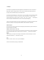
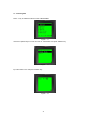
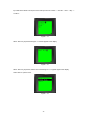
User’s Manual BCP-8000 Data Collector Ver.1 2011.02 Contents 1. Introduction .......................................................................................................................................... 1 1.1. Features ........................................................................................................................................... 1 1.2. Unpack ............................................................................................................................................. 1 1.3. Overview .......................................................................................................................................... 2 2. Keypad .................................................................................................................................................. 3 2.1. Function Keys .................................................................................................................................. 3 2.2. FN Key + Numeric Key .................................................................................................................... 3 2.3. Numeric and Alphabetic Keys .......................................................................................................... 4 3. Battery Care .......................................................................................................................................... 5 3.1. Charging the Battery ........................................................................................................................ 5 3.1.1. Recharge by the cradle with USB interface cable ................................................................. 5 3.1.2. Recharge by the cradle with RS-232 interface cable ............................................................ 6 3.1.3. Low Battery Warning............................................................................................................. 6 3.1.4. Auxiliary Battery .................................................................................................................... 7 3.1.5. Replace Battery .................................................................................................................... 7 4. Communication/Utility ......................................................................................................................... 8 4.1 Installing cradle with USB interface cable ......................................................................................... 8 4.2. Communication .............................................................................................................................. 9 5. Get Started .......................................................................................................................................... 10 5.1. Turn On .......................................................................................................................................... 10 5.2. Turn Off .......................................................................................................................................... 10 5.3. Main Menu ..................................................................................................................................... 10 5.3.1. Collect ............................................................................................................................... 11 5.3.2. Upload ............................................................................................................................... 11 5.3.3. Browse .............................................................................................................................. 12 5.3.4. Delete ................................................................................................................................ 13 5.3.5. Utilities .............................................................................................................................. 13 5.3.6. Download .......................................................................................................................... 18 6. Memory ............................................................................................................................................... 19 6.1. Memory ........................................................................................................................................ 19 6.2. Memory Near Full warning ............................................................................................................. 19 6.3. Memory Full warning ...................................................................................................................... 19 7. Example .............................................................................................................................................. 20 7.1. Collecting data ............................................................................................................................... 21 7.2. Lookup ........................................................................................................................................... 23 7.3. Browse ........................................................................................................................................... 24 1. Introduction BCP-8000 is a battery-operated portable data collector with lookup function. Equipped with high quality laser engine, it is easy and fast to acquire accurate barcode data. The ergonomic-built body offers comfortable grab to guaranty BCP-8000 ideal for long-time work. The vividly bright LCD display, tactile keypad (21 key), and small foot-print cradle furnish convenient operations and data processing: key-in, editing, navigation, communication and battery-charging. In addition, BCP-8000 provides a very user-friendly job generator utility. You need not create applications by writing the program source code anymore. With the aid of Job Generator, you may convert incomprehensible development process to simple steps and configurations and makes data collecting works become distinct and effortlessly. BCP-8000 is an ideal device for various data collecting applications, such as warehouse management, shop floor management, asset tracking…etc. 1.1. Features Job Generator offers users to design their own application easilly. High quality laser engine equipped makes barcode reading aggressively. The big capacity rechargeable battery endures long working time. A cradle offers communication and recharge via RS-232 or USB cables. A tactile 21 keys keypad provides works of barcode scan, data key-in, editing and navigation comfortably. Great sharp LCD with backlight furnishes clear and pleasant viewing. A capacious memory furnishes a large amount of data storage. 1.2. Unpack Standard Package BCP unit x 1 Cradle with USB interface for recharge and communication x 1 CD disk contains with BCP-8000 User’s Manual and BCP-8000 Job Generator Utility Operation Manual and example Job Application file x 1 Options Cradle with RS-232 interface for recharge/communication cable. Power adapter: 110V or 220V for cradle with RS-232 interface. Note: * The contents may vary with different options. * If there’s any physical damage or missing parts, please contact your supplier immediately. * Please keep all packing material and items as they were as the product may be send back terminal for service. 1 1.3. Overview FRONT VIEW SIDE VIEW REAR VIEW FRONT VIEW SIDE VIEW REAR VIEW 2 2. Keypad The terminal equips with 21 rubber keys. All the keys’ details/functions are described at Section 2.1, 2.2 and 2.3. 2.1. Function Keys Scan : Press to scan a barcode. Down : Press to cursor down. Up : Press to cursor up. Alpha : The toggle key to shift between Alphabet Upper Case, Lower Case and Numeric modes. Back Space : The back space key. Space : The space key. Enter : This key is for data enter confirmation or execution command. Power : The toggle key to shift between power on or power off. To avoid an accidental press, it requires pressing it for over 1.5 sec. to activate the terminal to power on or off. Function : The key has to associate with another numeric key to activate the functions. Please refer to Section 2.2 “ FN Key + Numeric Key” for further information. : Escape Exit or purge the current operation and back to previous operation/menu. 2.2. FN Key + Numeric Key Fn+0 (Backlight Switch): When operating under a low-light environment, press “FN” key then press “0” key; it would turn on the LCD backlight so as to acquire better images. Press “Fn” key then press “0” key again to turn off the backlight. 3 2.3. Numeric and Alphabetic Keys 1 (ABC)(abc) Numeric 1 or Alpha A,B,C or (a,b,c) 2 (DEF)(def) Numeric 2 or Alpha (D,E,F) or (d,e,f) 3 (GHI)(ghi) Numeric 3 or Alpha (G,H,I) or (g,h,i) 4 (JKL)(jkl) Numeric 4 or Alpha (J,K,L) or (j,k,l) 5 (MNO)(mno) Numeric 5 or Alpha (M,N,O) or (m,n,o) 6 (PQR) (pqr) Numeric 6 or Alpha (P,Q,R) or (p,q,r) 7 (STU)(stu) Numeric 7 or Alpha (S,T,U) or (s,t,u) 8 (VWX) (vwx) Numeric 8 or Alpha (V,W,X) or (v,w,x) 9 (YZ*)(yz*) Numeric 9 or Alpha (Y,Z) or symbol(*) or (y,z) or (*) ‧-%: Numeric (.) or Symbol (-, %, :) 0+$/ Numeric (0) or Symbol (+, $, /) 4 3. Connecting to Your PC BCP-8000 can easily perform data management, unit configuration and battery charge via the bundled cradle. The battery supplied in each terminal unit has been partially charged at the factory. It is recommended to charge the battery before first use. You can install the terminal unit to the bundled cradle and charges the battery either from USB or RS-232 interface cable. 3.1. Connecting to Your PC and Charging the Battery 3.1.1. Connecting to PC by the cradle with USB interface cable: USB Connector Connect the USB interface cable to the USB port on the PC. The ORANGE power LED in front of the cradle would be lighted. The cradle is ready for recharging the battery or terminal configuration. Place the terminal onto the cradle. You may hear a beep sound when the terminal is placed onto the cradle if the SETTING item “Key Click” is set to “Enable”. There is a LED indicator on the top of the terminal and lit RED. In the Display of the terminal there is a battery status icon indicates the battery status. As the battery is being charged, the battery status icon is varying and indicates the battery is charging. It takes approximately 6 hours to charge from low battery status.. When the battery is charged completely, the battery status icon will turn to static and indicated the battery is full (dark icon). The terminal RED LED turns off. * To install USB driver of BCP-8000, please refer to “4. Communication / Utility” for further information. 5 3.1.2. Connecting to PC by the cradle with RS-232 interface cable DB9F Connector to RS-232 Turn off computer before connection. Connect the DC plug of the power adapter to the power jack which located at the DB9F connector. Connect the DB9F connector (with power jack connected) to PC. Connect the AC Adaptor to an electrical outlet. The ORANGE power LED in front of the cradle would be lighted. The cradle is ready for recharging the battery or terminal configuration. Place the terminal onto the cradle. You may hear a beep sound when the terminal is placed onto the cradle if the SETTING item “Key Click” is set to “Enable”. There is a LED indicator on the top of the terminal and lit RED. In the Display of the terminal there is a battery status icon indicates the battery status. As the battery is being charged, the battery status icon is varying and indicates the battery is charging. It takes approximately 6 hours to charge from low battery status.. When the battery is charged completely, the battery status icon will turn to static and the terminal RED LED turns off. 3.1.3. Low Battery Warning When the battery available capacity drops low, a flashing empty battery icon will be appeared at the right bottom corner of the display. There are about 500 scans can be made after the warning occurred. When Low Battery Warning appears, terminate the work and put the terminal to the cradle and recharge immediately. 6 3.1.4. Auxiliary Battery The terminal is equipped with an auxiliary rechargeable battery to furnish the power supply to SRAM. The auxiliary battery can work at least one month since the main battery removed from the terminal or the main battery stores no power. Note: The maintenance or replacement of Auxiliary Battery is for qualified service personnel only. Any unauthorized changes or modifications could void the warranty. 3.1.5. Replace Battery In case you need to replace the battery on your own, follow the steps below. Step 1: Press and push to unlock the battery cover. Step 2: Remove the battery cover. Sep 3: Slight lift and remove the battery from the battery compartment. Step 4: Replace a new battery into the battery compartment and then replace the battery cover. Note: * Make sure to turn off the terminal and upload the data in the terminal before battery replacement. * Make sure the exposed cooper contacts of battery are engaged into the battery compartment. * Battery Disposal: Do Not dispose the battery and make sure to follow the battery recycling guidelines. 7 4. Communication/Utility 4.1 Installing Cradle with USB interface cable Installing USB Driver When you plug in the USB interface cable to your host PC for the first time, you will be prompted to install a device driver for the newly detected hardware. Insert the bundled Utility/Driver CD disk into an available CDROM on your PC. Specify the path to the USB Driver folder and complete the driver installation. You only need to install the device once. USB driver will automatically assign a virtual serial port (recommended) for communications. You can manually assign the COM Port. Enter the advance menu of the device for advanced configurations. Execute Start > Control Panel > System > Hardware > Device Manager > Ports (Com & LPT) will lead you to identify the port number. 8 4.2. Communication: You can configure your terminal and perform data management via the bundled cradle. Uploading: You can upload the data collected by your terminal unit to your PC. You may hear a beep sound when the terminal is placed onto the cradle. When uploading the data to your PC, the terminal would show “Uploading….” on the display and the GREEN LED will light on. When the task of uploading is completed, the message would disappear and the GREEN LED will light off. . Downloading: You can download the data from your terminal unit to your PC. Place your terminal onto the cradle and you may hear a beep sound when the terminal is properly placed. When downloading the data to your terminal, the terminal would show “Downloading….” on the display and the GREEN LED will light on. When the task of downloading is completed, the message would disappear and the GREEN LED will light off. 9 5. Getting Started 5.1. Turn On Press and hold the power key for over 1.5 second to turn on the terminal. The terminal might give a beep sound if the SETTING item “Key Click” is set to on. 5.2. Turn Off Press and hold the power key for over 1.5 second to turn off the terminal. The terminal might give a beep sound, if the SETTING item “Key Click” is set to on. 5.3. MAIN MENU For the first time use, when turn on the termtinal, the MAIN MENU would appear at the display. Figure 5.3 Note: Press the number key (1-6) or Arrow Up/Down keys to move the cursor to locate the selected item. Press “ENTER” key to enable the selected item. 10 5.3.1. COLLECT There is a preset application installed at the terminal. When the item is activated, the preset application, (figure 5.3.1) would appear at the display. Practice the example or press “ESC” key to return to MAIN MENU. Figure 5.3.1 5.3.2. Upload Data The Upload function can upload data which keep at the SRAM to PC. Please place the terminal onto cradle and connect to your PC before uploading the data. Execute the selected item or press “ESC” key to return to MAIN MENU. The example is that executing the “Upload Data” item; Figure 5.3.2 Figure 5.3.2.1 Note: This indicates the terminal is communicating with PC for data uploading. 11 5.3.3. BROWSE This function of the item is that allowing user to browse all the data which keep in the SRAM. Figure 5.3.3 Execute the selected item or press “ESC” key to return to MAIN MENU. The example is that executing the “Data File” item. Figure 5.3.3.1 Figure 5.3.3.1 shows the content of the data file. You can select the data file by using arrow keys (Up or Down) to browse the next data or the previous data. To edit or delete the presenting data, press “FN+1” to Edit and “FN+2” to delete the data file selected. Note: The edit and delete function are only available at data file while lookup file is not available with edit and delete function. 12 5.3.4. DELETE: The function allows user to delete the collected data. Figure 5.3.4 1. All Data: all the data would be deleted. 2. Last Record: last record would be deleted. 3. Cancel: all the data would be saved and return to Main Menu Figure 5.3.4.1 Select “1. Yes” to delete the data and “2. No” to quit. Execute the selected item or press “ESC” key to return to MAIN MENU (figure 5.3.4.1). 5.3.5. Utilities: The function of this item is that allowing user to set necessary parameters or some features that can help to enforce the terminal to meet application requirements. 13 Figure 5.3.5. 5.3.5.1. MEMORY: The item provides memory capacity checking and RAM Test. Figure 5.3.5.1. Execute the selected item or press “ESC” key to return to MAIN MENU. The example is that executing the RAM test. Figure 5.3.5.1.1 Note: The test is only carry out at the status of RAM empty. Please upload and delete the collected data in the terminal before RAM Test (figure 5.3.5.1.1). 14 5.3.5.2. SETTING: The function can configure the terminal parameters (auto power off, LCD backlight...) to optimize the convenient of the operation. Figure 5.3.5.2 1. Buzzer Pitch: The span between 000-255 Hz can be set. 2. Record Prompt: The span between 0000-9999 ms can be set. This is the time span to display the collected “record number” once the data file is saved to PC. 3. Date & Time: Set the correct Date/Time (yyyy/mm/dd) (hh:mm:ss). Figure 5.3.5.2.3 4. Power On: This item is for defining which display window would be appeared when turns terminal on. If “1. Resume” is set; whenever the terminal turns on, the last display window before terminal turns off would appear. If “2. Restart” is set; whenever the terminal turns on, the MAIN MENU would appear. 5. Auto Off: The span between 00-99 minute can be set to turn off the terminal if there is no action taken in the setting time. 6. Backlight: The span between 00-99 second can be set to turn off the LCD display if there is no action taken in the setting time. 7. Key Click: To enable or disable the click sound while the terminal works. 8. Deletion: The item provides the deletion of the collected data by manually or by automatically after data file upload to PC. 15 5.3.5.3. Reader: This item provides a test function to read barcodes. Press SCAN button, a red scan light beam will be emitted (for the safety reason, please DO NOT stare at aperture directly where the light come from). A beep with a flashing GREEN LED indicates a successful scan. If the scan button is pressed for over 2 seconds and the reading is not successful, the red scan light will turn off. Press the SCAN button and aim at the barcode to scan it again. Figure 5.3.5.3 Figure 5.3.5.3 shows the test barcode information including barcode data, type of barcode and the length of the barcode. 5.3.5.4. Test: The item provides self-test function of Buzzer, LCD/LED and keypad. Figure 5.3.5.4 16 Figure 5.3.5.4.1 Figure 5.3.5.4.1 shows that executing the keypad test, and key-in lower case of “apple” characters. Note: To alter states between upper case, lower case character and number, press “ALPHA” key to switch the type of characters or numbers. 5.3.5.5. Baud Rate: The item provides the setting of baud rate with variables from 1152000 bps down to 9600 bps. Figure 5.3.5.5 5.3.5.6. Version: This item provides showing Kernel Version of this terminal. Figure 5.3.5.6 17 5.3.6. Download: This download function provides selections of downloading the applications, lookup file, setting to the terminal. Figure 5.3.6 1. Program: This item provides the function of downloading the application which developed under the Job Generator Utility. 2. Setting: This item provides the function of downloading the setting file which programmed under the Job Generator Utility. 3. Update Kernel: This item provides function of downloading the new Kernel file. 4. Kernel Version: This item provides function of downloading the Kernel Version file. 5. Lookup File: This item provides function of downloading the Lookup file(s). The maximum lookup file is defined to 3 files (figure 5.3.6.5). 6. User ID: This item provides the function of downloading the user ID file. Figure 5.3.6.5 18 6. Memory 6.1. Memory Arrangement: The terminal is equipped with 2MB SRAM and it is divided into two portions with 1MB each for data and look-up file storages. A record is composed of FORM(s) or/and MENU(s). Each record can contain upto 10 FORM(s) or/and MENU(s). Each FORM can store upto 400 digits and each MENU can store upto 176 digits. The 1MB data storage memory can store maximum amount of record number upto 35000 recrods (based on the presumption of each record contains with 30 digits). The more digit contains in record the less record number is stored. 6.2. Memory Near Full Warning When the terminal’s memory capacity reaches to less than 5% of 1 mega byte of the data storage portion: A warning of “Memory Near Full” would appear on the display, (figure 6.2). To accentuate the user aware of memory status, it is designed blocking any actions on the terminal without removing the warning by press “ESC” key. Figure 6.2 Figure 6.3 6.3. Memory Full Warning When the terminal’s memory is full, a warning of “Memory Full” would appear on the display (figure 6.3). It would emit 5 beeps for every barcode scan or any “ENTER” key is pressed, and no save command is executed. Only by press “ESC” key to exit this. 19 7. Example The example is an applicable data collecting application which illustrates user with a circumstance of taking data in the filed, checking inventory on site, browse the collected data. Please find the file of tysso.apg under the EXAMPLE folder in the bundled CD disk. The example includes Employee ID, Location, Item No., Item, Qty variables. The data collecting job starts from key-in employee no., however, it is one time work. When the employee no. is filled in, the job sequence starts from key-in data to Lcoation -> Item No. -> Item -> Qty -> Location……. The example is also need a caption and selectable items to start or to end the job from beginning. Under the Job Generator Utility, the tysso.apg is developed based on the variables and sequence which framed at the example. The tysso.apg includes FORM1, FORM2 and MENU1 respectively. FORM1: Empl. ID: The way of key in the data is via barcode scan and keypad. (when finish the key-in data to the field, the terminal would jump into FORM2). FORM2: Location: Item No.:, Item:, Qty: The way of key in the data is via barcode scan and keypad. (when finish the key-in data to the fields, the terminal would start again routine of Location->Item No:->Item->Qty->……till “ESC” key is pressed). MENU1: “Tysso Inventory” is the caption of the example, and the selection to start the example or to end the example by the selection of “>Check Stock” and “Exit”, Note: Empl. ID:, Location: ,Item No.:, Item:, Qty: are all PROMPTs. User has to download the “tysso.apg” to the BCP-8000. 20 7.1. Collecting data Press “1” key to enable the collect function at MAIN MENU. Figure 7.1.1 Use Arrow Up/Down keys to move the cursor to “Check Stock” and press “ENTER” key. Figure 7.1.2 Input the number “100” and press “ENTER” key. Figure 7.1.3 21 Input data to the fields. The sequnce of the data input is from Location :-> Item No :-> Item :-> Qty :-> Location… Figure 7.1.4 When “ESC” key is pressed the figure 7.1.5 would appear at the display. Figure 7.1.5 When “ESC” key is pressed, exit the menu and the figure 7.1.2 appears again at the display. Select “Exit” to quit the menu. Figure 7.1.2 22 7.2. Lookup When user repeats the procedure of 7.1.4., user may trigger off the lookup function when the Item No. data matches the lookup file data. Follow the steps to produce the lookup function at 7.1.4. figure. Location: Shijr (Input Shijr and press “DOWN” or “ENTER” key ) Item No: 60001 (Input 60001 and press “DWON” or ENTER” key) The terminal would search the LOOKUP file checking if there is a matched data If there is a mateched data, then the terminal would bring all the information of the matched data to the display (figure 7.2.1). If there is no matched data, cursor would go to next field. Item: Input data and press “DOWN” or ENTER” key. Qty: Input data and press “ENTER” key. Location: item No: Figure 7.2.1 Note: You can move the cursor by using Arrow Up/Down keys to locate the contents to be changed. 23 7.3. Browse The browse function provides nevigation, edit or delete collected data. Press “3” key to enable the browse function at MAIN MENU. In sequence, the last saved record would be appeared at the display. The last saved record (as shown figure 7.3.2) would appear at the display. You can use Arrow Up/Down keys to navigate all the data or press “FN+1” or “FN+2” Keys to edit or delete the data (figure 7.3.3). Figure 7.3.2 Figure 7.3.3. 24