1
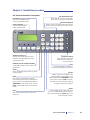
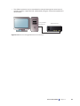
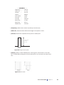
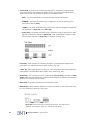
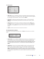
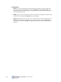
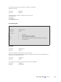
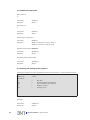
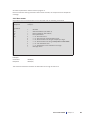
Current stimulator
Model CS200
User manual
Version 1.6
Current stimulator
Model CS200
Current stimulator - Model CS200
User manual
Trademarks
PowerLab® and LabChart® are registered trademarks of ADInstruments Pty Ltd. The names of specific
recording units, such as PowerLab 4/25, are trademarks of ADInstruments Pty Ltd.
Pentium is a registered trademark of the Intel Corporation. Windows, Windows 95, Windows 98,
Windows ME, Windows NT, Windows 2000, Windows XP and Vista are registered trademarks of Microsoft
Corporation. All other trademarks are the properties of their respective owners.
DMT reserves the right to alter specifications as required.
This document was, as far as possible, accurate at the time of printing. Changes may have been made to
the software and hardware it describes since then. New information may be supplied separately.
This documentation is provided with the DMT Current stimulator –
Model CS200 – Version 1.6
Document number: CS200 002A
No part of this document may be reproduced by any means without the prior written permission of
DMT.
Copyright © 2008 DMT A/S
DMT A/S
Skejbyparken 152
DK-8200 Aarhus N
Denmark
Tel.: +45 87 41 11 00
Fax: +45 87 41 11 01
www.dmt.dk
[email protected]
[email protected]
DMT - Asia
Everwin Gardens
Rm 502, Block B
521 Wanping Nan Lu
Shanghai 200030
China
Tel: + 86 (0) 21 64869685
Fax: + 86 (0) 21 64280591
www.dmt-asia.com
[email protected]
[email protected]
DMT-USA, Inc.
1201 Peachtree Street
400 Colony Square, Suite 200-630
Atlanta, GA 30361
USA
Tel.: +1 770 612 8014
Fax: +1 678 302 7013
www.dmt-usa.com
[email protected]
[email protected]
User manual CS200
Trademarks
Safety
The Current Generator has been designed for use only in teaching and research
applications. It is not intended for clinical or critical life-care use and should never
be used for these purposes: nor for the prevention, diagnosis, curing, treatment, or
alleviation of disease, injury, or handicap.
• Do not open the unit: the internal electronics pose a risk of electric shock.
• Do not use this apparatus near water.
• To reduce the risk of fire or electric shock, do not expose this apparatus
to rain or moisture. Objects filled with liquids should not be placed on the
apparatus.
• Do not block any ventilation openings. Install in accordance with the
manufacturer's instructions.
• Do not install near any heat sources such as radiators, heat registers, stoves,
or other apparatus that produce heat.
• Only use attachments and accessories specified by the manufacturer.
• Unplug this apparatus during lightning storms or when unused for long
periods of time.
• This apparatus must be grounded.
• Use a three-wire grounding-type cord similar to the one supplied with the
product.
• Do not defeat the safety purpose of the polarized or grounding-type plug.
A polarized plug has two flat blades, one being wider than the other. A
grounding type plug has two blades and a third (round) grounding pin. The
wide blade or the third prong is provided for your safety. If the provided plug
does not fit into your outlet, consult an electrician for replacement of the
obsolete outlet.
• Be advised that different operating voltages require the use of different types
of line cord and attachment plugs. Check the voltage in your area and use the
correct type. See the table below:
Voltage
Line plug according to standard
110–125 V
UL817 and CSA C22.2 No. 42.
220–230 V
CEE 7 page VII, SR section 107-2-D1/IEC 83, page C4.
240 V
BS 1363 of 1984. Specification for 13A fused plugs and switched and unswitched socket outlets.
Protect the power cord from being walked on or pinched: particularly at power plugs
and the point where they connect to the apparatus.
Refer all servicing to qualified service personnel. Servicing is required when the
apparatus has been damaged in any way; such as, the power-supply cord or plug
is damaged, liquid has spilled onto or objects have fallen into the apparatus, the
apparatus has been exposed to rain or moisture, does not operate normally, or has
been dropped.
Current stimulator
Model CS200
EMC / EMI
This equipment has been tested and found to comply with the limits for a Class
B Digital device, pursuant to part 15 of the FCC rules. These limits are designed
to provide reasonable protection against harmful interference in residential
installations. This equipment generates, uses and can radiate radio frequency
energy and, if not installed and used in accordance with the instructions, may cause
harmful interference to radio communications. However, there is no guarantee that
interference will not occur in a particular installation. If this equipment does cause
harmful interference to radio or television reception (which can be determined by
monitoring the interference while turning the equipment off and on), the user is
encouraged to correct the interference by one or more of the following measures:
• Reorient or relocate the receiving antenna.
• Increase the separation between the equipment and receiver.
• Connect the equipment into an outlet on a circuit different to that which the
receiver is connected to.
• Consult the dealer or an experienced radio/TV technician for help.
Approvals
Complies with the EMC standards:
EMC 89/336/EEC: EN 61326-2-6:2005
EN 61000-3-2.
Certified with the safety standards:
Directive 2006/95/EC: EN 61010-1:2001
EN 61010-1/Corr.1:2003
EN 61010-1/Corr.1:2003
EN 61010-2-101:2003
User manual CS200
Safety
Certificate of Conformity
DMT A/S, Skejbyparken 152, 8200 Aarhus N., Denmark,
hereby declares its responsibility that the following product:
Current Generator – Model CS200
Version 1.6
is covered by this certificate and marked with CE-label conforms
with the following standards:
EN 61010-1:2001
EN61010-1/Corr.1:2003
EN 61010-1/Corr.1:2003
EN 61010-2-101:2003
EN 61326-2-6:2005
Safety requirements for electrical equipment for
measurement, control, and laboratory use Part 1: General requirements.
Safety requirements for electrical equipment for
measurement, control and laboratory use - Part 2101: Particular requirements for in vitro diagnostic
(IVD) medical equipment.
Electrical equipment for measurement, control and
laboratory use - EMC
requirements - Part 2-6: Particular requirements - In
vitro diagnostic (IVD) medical equipment.
With reference to regulations in the following directives: 2006/95/EC, 89/336/EEC
Current stimulator
Model CS200
Contents
Trademarks . ................................................................................................... 3
Safety............................................................................................................... 4
EMC / EMI....................................................................................................... 5
Approvals......................................................................................................... 5
Certificate of Conformity................................................................................ 6
About this manual.......................................................................................... 8
Unpacking the Current stimulator unit......................................................... 9
Chapter 1 - Introduction................................................................................. 10
1.1 Document scope...................................................................................................... 10
1.2 Product overview..................................................................................................... 10
1.3 Features................................................................................................................... 10
Chapter 2 - Installation procedure................................................................ 11
2.1 Current Stimulator front panel................................................................................ 11
2.2 Current Stimulator rear panel................................................................................. 12
2.3 Installation............................................................................................................... 12
2.3.1 Stand alone, manual control............................................................................... 12
2.3.2 PC Controlled single device................................................................................. 12
Chapter 3 - Using the Current stimulator..................................................... 14
3.1 LCD display............................................................................................................... 14
3.2 Channel menu......................................................................................................... 14
3.3 Setup menu ............................................................................................................ 17
3.4 Communication submenu...................................................................................... 17
Chapter 4 - Serial protocol for CS200 . ........................................................ 19
4.1 PC serial port........................................................................................................... 19
4.2 Serial addresses...................................................................................................... 19
4.3 Address format........................................................................................................ 20
4.3.1 Requesting data................................................................................................... 20
4.3.2 Setting data.......................................................................................................... 21
4.3.3 Additional commands.......................................................................................... 22
4.3.4 Saving and loading stored programs.................................................................. 22
4.3.5 Error status........................................................................................................... 23
Appendix 1 - System specifications ............................................................. 24
Appendix 2 -Terms of warranty...................................................................... 25
Appendix 3 - Shipping instructions............................................................... 26
User manual CS200
Contents
About this manual
This manual contains a complete list of procedures describing how to install, and get
started using the Current stimulator unit – model CS200 – version 1.6.
Chapter 1 provides an introduction to the construction and basic features of the Current stimulator unit.
Chapter 2 describes step-by-step how to install a Current stimulator unit.
Chapter 3 is a complete manual to the Current Stimulator Unit. The chapter describes
in detail the construction of the menu system and how to use all the features of the
Current Stimulator Unit.
Chapter 4 contains procedures describing how to set up a serial protocol and requesting data.
Appendices contain various, additional information, about service and shipping
instructions.
Current stimulator
Model CS200
Unpacking the Current stimulator unit
Please take a few minutes to carefully inspect your new Current stimulator unit for
damage, which may have occurred during handling and shipping. If you suspect any
kind of damage, please contact us immediately and we will take care of the problems
as quickly as possible. If the packing material appears damaged, please retain it until
a possible claim has been settled.
We recommend that you store the packing material for any possible future transport
of the Current stimulator unit. In case of transport and the original packing material
is unavailable, please contact DMT Sales Department for advice and packing instructions.
After unpacking your new current stimulator unit please use the following list to check
that the system is complete:
•1 Current stimulator unit
•1 power cord*
•1 User manual
* The shape of the AC plug varies by country; be sure that the plug has the right
shape for your location
User manual CS200
Unpacking
Chapter 1 - Introduction
1.1 Document scope
This manual provides the information required to install and understand the principles of operating the CS200 combined pulse and train stimulator.
1.2 Product overview
The CS200 Current Stimulator combines simple and intuitive user operation with
sophisticated features that are required in electro physiology. The CS200 is a modular and highly versatile 4 channel current stimulator designed for use in combination
with DMT’s Myograph systems. It is optimized for electrical field stimulation of vascular smooth muscle, isolated skeletal muscle, or cardiac muscle. Furthermore for controlled neurotransmitter release from perivascular nerve-endings or skeletal muscle
motor nerve end plates.
The stimulator provides a variety of stimulation modes and protocols, such as single
continuous and frequency regulated steps. All parameters are easily entered from
the front panel and can be applied on an individual channel basis or to all channels
simultaneously. Once the programmed protocols have been determined, they can
be stored in one of five internal program memories to be re-loaded at any time. The
CS200 can easily be connected to a computer using the standard serial port, either
alone (using RS232 serial protocol) or in combination with up to 4 additional stimulators and maximal 4 myograph systems (using the RS485 serial protocol).
1.3 Features
The following features are common on the CS200 Current Stimulator.
Pulse stimulator:
• Pulse width 0.03 – 500ms
• Current 0 – 100mA
• Compliance 50 Volts
• Rise/fall time 1.5µs
• Output mono- or bi polar
Train stimulator:
• Frequency 0.1 – 256Hz
• Train duration 0.1 – 3600s
• Train delay 0.1-3600s
Frequency ramp
Internal memory can store up to five user defined current waveform protocols
External control through serial communication (RS232 / RS485)
10
Current stimulator
Model CS200
Chapter 2 - Installation procedure
2.1 Current stimulator front panel
Up and down arrows
Will move the cursor in the display
to the next or previous menu-item.
LCD display
Channel and CS200 setup
menu are displayed here.
Numerical keypad
Used to enter numerical values for various
menu items in the channel or setup menus
Power indicator
A yellow LED indicates
power switched ON.
Start
Chan.
1
Chan.
2
Chan.
3
Chan.
4
Setup
Channel selectors
Change the active channel menu
shown in the LCD display by pressing these buttons.
Channel current output indicators
A red LED indicates active pulse train
generation.
Setup
Enter the CS200 setup menu by pressing this button.
Start
Start current stimulation using the
stimulation protocol of the channel currently visible in the LCD display. When
[SYNCRON] in the setup menu is set to
[YES], all channels will start simultaneously.
Stop
Stop current stimulation of one or all
channels.
Stop
Single
Enter
1
2
3
Chan. 1
4
5
6
Chan. 2
7
8
9
Esc
0
.
Chan. 3
Chan. 4
Channel output
Four shielded, standard
BNC channel output signal connectors.
Esc
Undo all changes to the menu
items by pressing the escape key.
Single
Starts output of a single current
pulse of the channel shown in the
LCD display. When [SYNCRON] in the
setup menu is set to [YES], all channels will start simultaneously, giving
a single current pulse output.
Enter
Any changes of the values of menu
items in the LCD display will be permanent after pressing the [Enter] key, until
a new change is made.
User manual CS200
Chapter 2
11
2.2 Current Stimulator rear panel
Ground
Ground can be connected to the
common ground that connects all
grounded equipment in the experimental set up.
Power switch and plug (AC)
GND
O
I
RS485
Serial output RS485
DB9 serial output allowing interaction
with the serial port of a PC. The RS485
serial protocol allows several serial
instruments to be connected in series.
The use of RS485 serial output requires
a RS485 converter that is connected
between the PC serial port and the serial
instrument.
RS485
RS232
Serial output RS232
DB9 serial output allowing interaction with
the serial port of a PC. The RS232 serial
protocol allows interaction of a PC with one
serial device. Serial commands and references are explained in detail.
2.3 Installation
2.3.1 Stand alone, manual control
• Use the supplied power cord for connecting the CS200 Current Stimulator to the
power supply. Be sure that the power cord is compatible with your local power
supply.
• Connect channel outputs to the electrodes of your experimental set up using a
BNC connector. Typically platinum electrodes fit into an organ bath.
2.3.2 PC Controlled single device
A PC can control the function of the CS200 Current Stimulator. If only one serial
device is connected to the PC serial port, the RS232 serial output situated on the
backside of the Current Stimulator should be used
• Connect the R232 serial output to the PC serial port with a 9 pin (DB9) serial
cable. Use a DB9 to DB25 converter if the PC serial output consists of a 25-pin,
instead of a 9-pin socket.
12
Current stimulator
Model CS200
• The CS200 operation can be controlled for example through the serial communication program ‘HyperTerminal’ (Windows®) using the commands explained in
detail below.
To any available
PC serial port
CS200 rear view
GND
I
O
RS485
RS485
RS232
CS200 serial output
Figure 2.3.2 PC control through RS232 serial connection
User manual CS200
Chapter 2
13
Chapter 3 - Using the Current stimulator
3.1 LCD display
• The LCD display is the user interface of the CS200, for manual control of the Current Stimulator.
• The first line of the display always indicates the menu item currently selected.
Menu items can be divided into channel menus and setup menus.
• The second line is always the INPUT line. The input line is indicated by [>] instead
of [:].
• The numerical key pad is used to enter new data at the input line. Following data
entry [Enter] is pressed to store the new data entry at the input line.
• Pressing [Esc] can erase an erroneous data entry.
• All non-numerical menu items (e.g. Output: Mono or Bipolar) can be changed by
pressing [Enter] until the desired change.
• Scroll through the menu displayed in the LCD display by pressing the up or down
arrows, respectively.
• The LCD display reads [ERROR] on the entry line if entered data is outside the
range indicated by the specifications of the CS200 Current Stimulator.
• Frequency and pulse duration that are not compatible with each other (e.g. frequency of 200 Hz and pulse duration of 10ms) will also results in a [ERROR] message in the entry line. Thus, there always has to be at least 1 ms between pulse
duration and the reciprocal frequency (i.e. 1 / frequency).
• The first line of the LCD display will show blinking asterisks [**] indicating that a
stimulation protocol has been started and is running.
• The display indicates [--RESISTANCE TOO HIGH--] if the electrical resistance at
the electrodes is too high for the current that has been set in the stimulation
protocol. Typically this occurs if electrodes are not immersed in physiological salt
solution, i.e. if the Current Stimulator is started with the electrodes in air.
3.2 Channel menu
Every available channel has its own channel menu that can be accessed by pressing the appropriate channel selector on the front panel (see page 11). The channel
number will be displayed in the first line of the LCD display. Every channel pulse
protocol can be changed individually by pressing the respective channel selector and
entering the appropriate values for the pulse and train parameters for that particular channel. Alternatively, all channel pulse and train parameters can be changed
simultaneously if [SYNCRON] is set to [YES] in the Setup menu. In this case entering
values for a parameter in the channel menu of CHANNEL 1 will also change the same
parameter in all other channels available.
14
Current stimulator
Model CS200
-- CHANNEL 1 -Frequency >
100 Hz
Pulse dur. :
0.1 ms
Current
:
50 mA
Output
:
MONO
Train mode :
CONT.
Train dur. :
3 sec
Train dly.
:
180 sec
Start Freq. :
0.5 Hz
Stop Freq. :
64 Hz
Repeat dly. :
120 sec
• [Frequency] defines the number of pulses per second (Hz).
• [Pulse dur.] Pulse duration defines the length of the pulse in msec.
• [Current] defines the amplitude of the pulse in milliampere.
Current = Pulse
amplitude
Unit = mA
Pulse duration
Unit = ms
Figure 3.2 Single current pulse
• [Output] polarity is either MONO polar, meaning that current flows in one direction, or BIPOLAR meaning that current alternates in one and then the other direction.
Figure 3.3 Train mode
User manual CS200
Chapter 3
15
• [Train mode] A pulse train consists of pulses with a frequency, pulse duration,
current amplitude and polarity as defined in the menu-items described above.
Three train modes can be entered which are described below.
• [OFF]: The pulse stimulator runs continuously without interruption.
• [SINGLE]: The pulse stimulator runs a single train of pulses defined by the
menu items above [Train]
• [CONT.]: The pulse stimulator runs pulse trains with the length and delay that
are indicated in [Train dur.] and [Train dly.]
• [Freq. Step]: The pulse stimulator runs a frequency ramp of pulse trains, starting with a frequency defined in [Start freq.] and doubling the frequency until
the frequency defined in [Stop freq.] is reached. (see fig. 3.5)
Figure 3.4
• [Train dur.] Train duration is entered in seconds. It indicates the length of the
pulse train (see black bars below CONT. mode in fig. 3.4)
• [Train dly.] Train delay entered in seconds. This determines the interval between
pulse trains (see white bars below CONT. Train mode in fig. 3.4)
• [Start freq.] This menu item is only of relevance if [Freq. step] is chosen in [Train
mode] otherwise this parameter is ignored. Start frequency defines the frequency
at which the frequency ramp starts.
• [Stop freq.] Final step frequency of the frequency ramp.
• [Repeat dly.] Delay between frequency ramps in seconds. If this parameter is set
to 0, the frequency ramp runs only once.
Figure 3.5 Pulse trains with increasing frequencies. The length of the
white bar below equals (Train dur.), the black (train delay)
16
Current stimulator
Model CS200
3.3 Setup menu
--
SETUP
--
Save prog. >
1
Get prog.
:
1
Syncron
:
YES
Copy chan. :
1 TO ALL
Option
0
:
• [Save prog.] Up to 5 stimulation protocols, including all channel parameter information can be stored in an internal memory. Store the present channel programs
by choosing a number between 1 and 5 and press [Enter].
• [Get prog.] By finding the appropriate program number (1 to 5) and pressing
[Enter] one of the stimulation protocols that are stored in the memory can be
retrieved.
• [Syncron] When this menu-item is enabled, by setting its value to [YES], pressing [Start] will result in simultaneous starting of all channels. When [Syncron] is
set to [NO], pressing [Start] will only start the channel that is visible in the LCD
display.
• [Option] contains service and communication submenus.
3.4 Communication submenu
To reach the communication submenu, press 7 [Enter] under options in the setup
menu.
--
COMM. MENU
--
Serial mode >
RS485
Channel no. :
1-4
• [Serial mode] Here the RS232 or RS485 serial protocol is set. Using RS232, only
1 serial device, e.g. one current stimulator can be connected to one PC serial
port (see section 2.3.2, PC controlled single device). Choosing RS485 enables
connecting multiple serial devices to a single PC serial port (see section 2.3.3 PC
controlled multiple serial devices). To chose between RS232 and RS485 press
[Enter]
• [Channel no.] This line is only visible if RS485 is chosen in the previous menu
[Serial mode]. Channel numbers for the current stimulator are defined in this
menu. Choose channel numbers for CS200: 1-4, 5-8, 9-12, 13-16 by pressing
[Enter]. Thus 4 CS200 can be connected in series to one PC serial port together
with four 610M multi-myograph or four 700 MO tissue bath systems. The channel
numbers that are entered in this menu will be visible at the first line of the channel menu.
User manual CS200
Chapter 3
17
3.5 Keyboard
• [Start] The Current Stimulator starts electrical stimulation by pressing the start
key on the keypad. Depending on whether [Syncron] is set to [Yes] or [No], all
channels will start simultaneously, or one channel, the channel currently active in
the LCD display will start.
• [STOP] Ends current output from the active channel in the display, or ends current
output from all channels if [Syncron] was set to [Yes].
• [Single] pressing this key will start only a single pulse of the active channel in the
display with the pulse length defined in the channel menu. Again if [Syncron] in
the setup menu was set to [Yes], a single pulse will start on all channels simultaneously.
18
Current stimulator
Model CS200
Chapter 4 - Serial protocol for CS200
The CS200 Current Stimulator can be controlled remotely through a PC serial connection. Depending on whether the RS232 or RS485 serial protocol are chosen, either a
single or multiple current stimulators connected in series can be controlled when connected to a single PC serial port (see page 12). CS200 operation can be controlled
for example through the serial communication program ‘HyperTerminal’ (Windows®)
using the commands explained below.
4.1 PC serial port
The PC Serial port parameters should be set to the following values:
• Bits per second = 9600
• Data bits = 8
• Parity = none
• Stop bits = 0
• Flow control = none
4.2 Serial addresses
The current stimulators receives the address range #80 - #90 with a possibility to
connect 4 CS200 to the same PC serial port.
CS200
Channel 1-4
#80-#83 (single stimulator addresses)
Channel 5-8
#84-#87
Channel 9-12
#88-#8B
Channel 13-16
#8C-#8F
Table 1 Channel addresses
User manual CS200
Chapter 4
19
Version No.
#00
Frequency
#01
Pulse dur.
#02
Current
#03
Output
#04
Train mode
#05
Train dur.
#06
Train dly.
#07
Start freq.
#08
Stop freq.
#09
Repeat dly.
#10
Start
#80
Stop
#81
Single
#82
Syncron
#83
Save program
#84
Get program
#85
Error status
#87
These three parameters
only in combination with
#80
Table 2 internal addresses (non-hexadecimal)
4.3 Address format
4.3.1 Requesting data
Command
Response
For which:
aa
pp
xxxx
(cr)
?aapp(cr)
>aa,pp,xxxx(cr)
?
=Request data
=Channel address (see Table 1)
=Internal address (see Table 2)
=Data returned from CS200 (length depending on data type)
=Carriage return
Example:
Command
response
20
?8003(cr)
>80,03,0020(cr)
Current stimulator
Model CS200
The value for [Current] on stimulator 1, channel 1 is requested.
Response is 20 mA.
Command
response
?8005(cr)
>80,C(cr)
The status of Train mode is requested. The reply can be:
C for CONTINUE
O for OFF
S for SINGLE
F for FREQUENCY STEP
4.3.2 Setting data
Command
Response
=aappxxxx.x(cr)
>aa(cr)
For which:
=
aa
pp
xxxx.x
(cr)
=
=
=
=
=
Set data
Channel address (see Table 1)
Internal address (see Table 2)
New values for stimulator (length depending on data type)
Carriage return
Example
Example:
Command
response
=8003100(cr)
>80(cr)
Current on channel 1 of stimulator 1 is set to 100 mA.
Data sent to the Current Stimulator will NOT be changed if they are outside the ranges of the
respective stimulation parameters.
Command
response
=8005C(cr)
>80(cr)
This command will set the train mode on channel 1 to CONTINUE.
Command
response
=8086C(cr)
no response
User manual CS200
Chapter 4
21
4.3.3 Additional commands
Start Channel
1
Command
Response
=8080(cr)
>80(cr)
Stop Channel
1
Command
Response
=8081(cr)
>80(cr)
Check status of channel 1
Command
Response
?8080(cr)
>80Y(cr) (channel 1 is On [Y = Yes]) or
>80N(cr) (channel 1 is Off [N = No])
Synchronize channels ([Syncron])
Command
Response
=8083Y(cr)
>80(cr)
Do NOT synchronize channels
Command
Response
=8083N(cr)
>80(cr)
4.3.4 Saving and loading stored programs
Stimulation programs that are uploaded from a PC can be stored in, or retrieved from internal
memory
using the following
command:
Command
=aappx(cr)
Response
>aa(cr)
For which:
=
aa
pp
x
(cr)
=
=
=
=
=
Set data
Channel address (see Table 1)
Internal address (see Table 2)
Program number
Carriage return
Example:
Command
Response
22
=80841(cr)
>80(cr)
Current stimulator
Model CS200
All channel parameters will be stored in program 1.
Note that because storing data takes about three seconds, the response will be delayed accordingly.
4.3.5 Error status
Any internal error in the stimulator can be retrieved with the following commands
Command
?aapp(cr)
Response
>aaxy(cr)
For which:
=
aa
pp
xy
(cr)
=
=
=
=
o
o
o
o
o
o
=
Set data
Channel address (see Table 1)
Internal address (see Table 2)
Error parameters
x = 0 : No timer errors
x = 1 : Internal timer communication error
x = 2 : Pulse duration too long or frequency to high
x = 3 : Pulse duration too long in FREQUENCY STEP MODE
y = 0 : No resistance error
y = 1 : Resistance in the chamber is too high
Carriage return
Example:
Command
Response
=8087(cr)
>8001(cr)
The electrical resistance between the electrodes is too high at channel 1.
User manual CS200
Chapter 4
23
Appendix 1 - System specifications
Pulse generator:
Frequency:
Pulse duration:
Current:
Compliance:
Rise/fall time:
Output:
Voltage: Train generator:
Mode 1:
Mode 2:
Mode 3:
Mode 4:
Train duration:
Train delay:
24
0.1 - 256Hz
0.03 - 500msec
0 - 100mA
50 Volts
1.5msec
Mono/Bipolar
100 to 240 VAC (auto) 50 / 60 HZ
Off
Single
Continues
Frequency step
0.1 - 3600sec.
0.1 - 3600sec.
Current stimulator
Model CS200
Appendix 2 -Terms of warranty
Warranty
DMT A/S warrants to the original user that Current Stimulator Unit manufactured by
DMT A/S will be free from defects in materials and workmanship for a period of three
years after the date of delivery. DMT A/S will repair or replace any defective part, subject to the conditions, limitations and exclusions.
Exclusions
Force and pressure transducers, separately or part of Current Stimulator Unit manufactured by DMT A/S, are disclaimed from any warranty.
Limitations
This warranty shall not apply to equipment subjected to accidental damage, improper
use, alteration, or deterioration.
Warranty on third-party products will be as determined by their respective manufacturer.
DMT A/S shall not be liable for consequential, incidental, special, or other direct or
indirect damages resulting from economic loss or property damage sustained by you
or any end user from the use of the products sold or services rendered hereunder.
Warranty Returns
A “Return Material Authorization” (RMA) number is required for all returns. This
number should be clearly indicated on all returned Current Stimulator Unit. Due to
improper or inadequate packaging when returned for RMA purposes are not granted
warranty coverage are not granted.
User manual CS200
Appendix 2
25
Appendix 3 - Shipping instructions
If the Current Stimulator Unit needs to be send back for service or repair, please read
the following shipping instructions very carefully.
Before you start packing the current stimulator unit, please remember that you are
dealing with very delicate equipment and therefore care must be taken. DMT recommends that each part of the current stimulator unit system be wrapped individually
(i.e. with bubble wrap) and placed together in a large box (preferable the box you once
received the current stimulator unit in). Place the wrapped items in the middle of the
box and fill out the surroundings with chips of expanded polystyrene.
Important:
Before closing the box, make sure that no enclosed items can be shaken around as
transport by road or air from time to time can be quite roughly.
Address the box to:
DMT A/S
Skejbyparken 152
DK-8200 Aarhus N
Denmark
Make sure that all four sides of the box are marked “fragile” or similar. Make an indication on the top of the box that it contains goods returned for repair/service.
Customers outside the EC must further enclose a pro forma invoice stating that the
box contains goods being returned for repair or service.
If arranging transportation through a courier, please keep in mind the high value of
the current stimulator unit and that a standard insurance provided by the courier in
most cases is insufficient to cover damage or loss of the current stimulator unit. In
most cases an additional insurance coverage is needed.
26
Current stimulator
Model CS200
DMT A/S
Skejbyparken 152
DK-8200 Aarhus N
Denmark
Tel.: +45 87 41 11 00
Fax: +45 87 41 11 01
www.dmt.dk
[email protected]
[email protected]
DMT - Asia
Everwin Gardens
Rm 502, Block B
521 Wanping Nan Lu
Shanghai 200030
China
Tel: + 86 (0) 21 64869685
Fax: + 86 (0) 21 64280591
www.dmt-asia.com
[email protected]
[email protected]
DMT-USA, Inc.
1201 Peachtree Street
400 Colony Square, Suite 200-630
Atlanta, GA 30361
USA
Tel.: +1 770 612 8014
Fax: +1 678 302 7013
www.dmt-usa.com
[email protected]
[email protected]