1
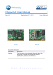
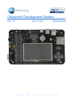
ChipworkX User Manual
Rev.4.3
March 11, 2011
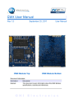
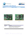
Top View
User Manual
Back View
Document Information
Information
Description
Abstract
This document covers complete information about
ChipworkX Module and Development System,
specifications, tutorials, and references.
G H I
E l e c t r o n i c s
GHI Electronics,LLC
ChipworkX User Manual
Revision History
Date
Modification
03/11/11
Various updates
09/14/10
Updated in-field update section
07/21/10
Updated information for NETMF 4.1
04/26/10
Updated network section
04/02/10
Updates and fixes
03/12/10
First version
Rev.4.3
Page 2 of 51
www.ghielectronics.com
GHI Electronics,LLC
ChipworkX User Manual
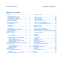
Table of Contents
Table of Contents
1.Introduction...................................................................................4
1.1.What is Microsoft .NET Micro Framework (NETMF)?.........4
1.2.NETMF - Porting vs. Using..................................................4
1.3.GHI's .NET Micro Framework Based Solutions..................5
1.4.What is ChipworkX Module?...............................................5
1.5.Extended Framework Features...........................................6
1.6.ChipworkX Key Features.....................................................6
1.7.Example Applications..........................................................7
2.ChipworkX Development System.................................................8
3.ChipworkX Module Architecture..................................................10
3.1.Block Diagram...................................................................10
3.2.AT91SAM9261S Microcontroller.......................................11
3.3.SDRAM..............................................................................11
3.4.NOR Flash.........................................................................11
3.5.NAND Flash.......................................................................11
3.6.Serial DATAFLASH ..........................................................11
3.7.Ethernet PHY.....................................................................11
3.8.Runtime Loadable Procedure (RLP).................................12
3.9.Database Support..............................................................12
4.Pin-Out Description.....................................................................13
5.ChipworkX On Boot Up...............................................................17
5.1.Bootstrap Loader vs. TinyBooter vs. ChipworkX Firmware
.................................................................................................20
5.2.ChipworkX Access Interface..............................................21
Other Interfaces.................................................................21
6.TinyBooter...................................................................................22
6.1.TinyBooter update using bootstrap loader........................22
Erasing Process:...............................................................22
Emergency Bootstrap access...........................................22
Installing TinyBooter Updater USB Driver:........................23
Updating Tinybooter:.........................................................23
6.2.ChipworkX firmware update through TinyBooter..............24
7.ChipworkX Firmware...................................................................27
7.1.Getting Started with ChipworkX........................................27
All you need to start up.....................................................27
Development System First Power-up...............................28
Adding GHI NETMF Library..............................................32
7.2.ChipworkX Emulator..........................................................34
8.ChipworkX Features...................................................................35
8.1.Application Flash/RAM/EWR.............................................35
Extended Week References (EWR).................................35
NAND Flash......................................................................35
8.2.Debugging Interface (Access Interface)............................35
8.3.Digital Inputs/Outputs........................................................36
Rev.4.3
8.4.Serial Peripherals..............................................................37
Serial Port (UART)............................................................37
SPI.....................................................................................37
I2C.....................................................................................38
One-wire Interface.............................................................38
8.5.Networking (TCP/IP)..........................................................38
MAC address setting.........................................................38
IP address (DHCP or static):.............................................39
Ethernet.............................................................................39
Wireless LAN WiFi (IEEE 802.11b)...................................40
PPP (TCP/IP access through serial modems)..................41
SSL....................................................................................41
8.6.Graphics / Display.............................................................41
8.7.PWM..................................................................................42
8.8.Touch Screen Control........................................................42
8.9.USB Device (Client) ..........................................................43
USB cable connection detection.......................................43
8.10.USB Host and Supported USB Drivers...........................44
8.11.Storage Devices (Internal Flash, SD, USB) / File System
.................................................................................................44
Internal Flash Storage.......................................................44
SD/MMC Memory..............................................................44
USB Memory.....................................................................45
8.12.Output Compare..............................................................45
8.13.Database.........................................................................45
8.14.Power Control / Hibernate...............................................45
Power Control....................................................................45
Hibernate...........................................................................45
8.15.Real Time Clock..............................................................46
8.16.Battery RAM....................................................................46
8.17.Processor Register Access.............................................46
8.18.JTAG access....................................................................46
8.19.Runtime Loadable Procedure RLP.................................46
8.20.In-Field Update................................................................47
8.21.Watchdog.........................................................................47
9.Advanced Users..........................................................................48
10.ChipworkX design Consideration..............................................48
10.1.Hardware.........................................................................48
10.2.Software...........................................................................48
10.3.ChipworkX Placement.....................................................49
Appendix A: MFDeploy Tool...........................................................50
Legal Notice...................................................................................51
Licensing..................................................................................51
Disclaimer................................................................................51
Page 3 of 51
www.ghielectronics.com
GHI Electronics,LLC
ChipworkX User Manual
Introduction
1. Introduction
1.1. What is Microsoft .NET Micro Framework (NETMF)?
Microsoft .NET Micro Framework is a lightweight implementation of .NET Framework. It
focuses on the specific requirements of resource-constrained embedded systems.
Supporting development in C# and debugging on an emulation or the device, both using
Microsoft's Visual Studio. The .NET Micro Framework is also open source, released under
the Apache 2.0 license and completely free.
Developers already experienced with .NET and Visual Studio can take advantage of their
skills immediately reducing the learning curve. The actual C# application development
process is completely shielded from the low-level design details of the hardware platform.
Combining the benefits with off-the-shelf, low-cost, network-enabled embedded systems
creates a rapid product development solution.
1.2. NETMF - Porting vs. Using
There are two sides to working with NETMF, porting it and using it. For example, writing a
JAVA game on a cell phone is much easier than porting the JAVA virtual machine (JVM) to
the phone. The phone manufacturer did all the hard work of porting JAVA to their phone
allowing the game programmers to use it with ease. NETMF works the same way, porting
is not easy but using it is effortless.
NETMF can be split into two major components, the core (CLR) and HAL (Hardware
Access Layer). The core libraries are made so they are hardware independent. Usually, no
modifications are needed on the core libraries. A developer porting NETMF for a hardware
platform will need to make the HAL to handle interfacing the hardware control to upper
layers.
According to GHI's experience with NETMF porting, it is not feasible to work on porting
NETMF to your new hardware in case you are targeting medium or low quantities annually
(less than 100,000 units). A faster-to-market option is by using one of the available OEM
modules/chipsets. These OEM devices have everything you need built in the hardware
and software.
Rev.4.3
Page 4 of 51
www.ghielectronics.com
GHI Electronics,LLC
ChipworkX User Manual
Introduction
1.3. GHI's .NET Micro Framework Based Solutions
With GHI Electronics, you're getting an experienced partner that offers a wide range of
.NET Micro Framework hardware and software capabilities using the various drop-in
modules/chipsets such as ChipworkX, Embedded Master, ChipworkX and USBizi. In
addition, our free unlimited support is available to assist you at any point. New features
and fixes come seamlessly to your product at no cost to you.
On top of the great features that .NET Micro Framework provides, such as Ethernet,
graphics and touch screen, GHI solutions has additional exclusive features such as USB
host, PPP (GPRS/3G), database and native code runtime libraries (RLP). All these
exclusive features are included at no extra cost to you.
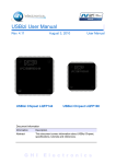
1.4. What is ChipworkX Module?
ChipworkX Module is a combination of hardware (ARM9 Processor, Flash, RAM, Ethernet
PHY...etc) on a small (67.6mm x47mm) OEM board MINI9261I with SO-DIMM200 slot that
hosts Microsoft .NET Micro Framework with various PAL/HAL drivers. In addition to the
benefits of .NET Micro Framework, ChipworkX includes exclusive software and hardware
features.
ChipworkX Module is a vastly sophisticated piece of hardware. This complexity provides
the end-user with a remarkably simple platform to implement in any hardware design.
Looking at the ChipworkX Development System schematic shows just how simple it really
is. All you need is 3.3 volts and some connections to bring the latest technologies to your
products. With manageable features like USB host, database and WiFi, the possibilities
are boundless.
Rev.4.3
Page 5 of 51
www.ghielectronics.com
GHI Electronics,LLC
ChipworkX User Manual
Introduction
Back View
Top View
1.5. Extended Framework Features
ChipworkX supports a complete set of .NET Micro Framework features such as TCP/IP,
SSL, FAT, USB device and more. Including support for other exclusive GHI features
such as full USB host stack, CAN, ADC, DAC,PPP, GPRS, 3G, etc. ChipworkX also
allows developers to load their own compiled native code.
Furthermore, ChipworkX™ supports SQLite database, allowing fast logging and
retrieval of standard SQL quires.
For real-time and high processing needs, Runtime Loadable Procedures, allow users to
load their own compiled native code (C or assembly) to run directly through manged
Micro Framework, similar to the use of DLLs on PCs.
1.6. ChipworkX Key Features
●
●
●
●
●
●
●
●
●
●
●
●
●
●
Rev.4.3
.NET Micro Framework
200 MHz 32-bit ARM9 Processor,
AT91SAM9261S
64MB RAM
8MB FLASH
256MB Internal Flash with File System
Embedded LCD controller
Embedded Ethernet PHY with fast
DMA communication.
Runtime Loadable Procedure
Full TCP/IP Stack
Web Services
SSL
ZG2100 WiFi Driver
PPP ( GPRS/ 3G )
DPWS
Page 6 of 51
●
●
●
●
●
●
●
●
●
●
●
●
●
Embedded USB host/device
80 Digital I/O Pins with interrupt
capabilities.
2 SPI (8/16bit)
I2C
3 UART
1 PWM
3.3V I/Os voltage
0ºC to +70ºC Operational
Power Consumption (TBD) mA
Low Power Mode (TBD) mA
67.6mmx47mm
Easily attached with SO-DIMM200
slot.
RoHS, Lead Free
www.ghielectronics.com
GHI Electronics,LLC
ChipworkX User Manual
Introduction
1.7. Example Applications
●
●
●
●
●
●
●
●
●
●
●
Rev.4.3
Designs with intensive processing or time-critical routines (using RLP)
Vending machine
Measurement tool or tester
Network server device
Robotics
GPS navigation
Medical instrument (with a color touch screen display).
Central alarm system
Smart appliances
Industrial automation devices
Windows SideShow devices
Page 7 of 51
www.ghielectronics.com
GHI Electronics,LLC
ChipworkX User Manual
ChipworkX Development System
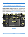
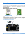
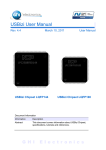
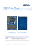
2. ChipworkX Development System
ChipworkX Development System is the official kit from GHI Electronics for the
ChipworkX module. This kit exposes the various peripherals and interfaces that make it an
ideal starting point for any .NET Micro Framework project. Furthermore, most of
ChipworkX module signals such as GPIO, SPI and UART are accessible on a 0.1" header
for rapid prototyping.
ChipworkX Development System Brochure and Pin-outs Document provides for a more
detailed view of this system.
L-Speaker
2 LED
XBee
connector
XBee LEDs
Pow er
Connector
JTAG
USB Client
SV5 header
SV1 header
3D
Accelerometer
UEXT header
Dual Port
USB Host
RJ45
Ethernet
R-Speaker
RTC
Battery
SD/MMC
connector
Pow er
LEDs
4.3” TFT Display
With touch screen
RS232
D-SUB
Buttons Pad
SV2 header
Front View
Rev.4.3
Page 8 of 51
www.ghielectronics.com
GHI Electronics,LLC
ChipworkX User Manual
ChipworkX Development System
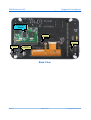
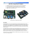
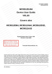
ChipworkX
Module
Touch
Controller
RS232 level
converter
Stereo Audio
Connector
VS1053
MP3/MIDI decoder
Back View
Rev.4.3
Page 9 of 51
www.ghielectronics.com
GHI Electronics,LLC
ChipworkX User Manual
ChipworkX Module Architecture
3. ChipworkX Module Architecture
ChipworkX is a combination of hardware (ARM Processor, Flash, RAM, Ethernet
PHY...etc) that hosts Microsoft .NET Micro Framework with various PAL/HAL drivers. In
addition to the benefits of .NET Micro Framework, ChipworkX includes exclusive software
and hardware features, such as support for USB host, PPP networking and more.
The (67.6mm x47mm) MINI9261-I module contains everything needed to run .NET Micro
Framework. The module is a sophisticated piece of hardware developed with a complex
BGA design. This complexity provides the end-user with a remarkably simple platform to
implement in any hardware design.
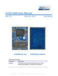
3.1. Block Diagram
.NET and GHI
Managed Library
GHI RLP
loader
.NET Micro Framework
CLR
ChipworkX Module
Hardware
64 MB SDRAM
User Runtime Loadable
Procedure region
8MB NOR
Flash for
User
4MB
serial
Data
256MB NAND FLASH
With FAT File System
PAL
HAL
200MHz ARM9 CPU
Peripherals:GPIO,
GHI Extended features:
USB Drivers, Hardware Access
10/100
Ethernet PHY
GHI RLP
Rev.4.3
Interrupts, PWM,USB HC,
USB Device,
LCD Controller,
Ethernet Controller ...etc
Page 10 of 51
www.ghielectronics.com
GHI Electronics,LLC
ChipworkX User Manual
ChipworkX Module Architecture
3.2. AT91SAM9261S Microcontroller
AT91SAM9261S 200Mhz ARM9 32-bit processor is the core of ChipworkX Module.
ChipworkX firmware includes HAL and PAL drivers for the various peripherals of this
microcontroller that can be accessed from the user's managed code.
We recommend you consult the AT91SAM9261S user manual for detailed information on
things such as registers, hardware and electrical characteristics.
3.3. SDRAM
64MB of SDRAM comes standard with ChipworkX Module. Approximately 2MB is reserved
for developers native executable data, that includes the Runtime Loadable Procedures.
3.4. NOR Flash
8MB of NOR flash is available on ChipworkX Modules. This memory is used for ChipworkX
firmware, user managed code and Extended Week References.
To ensure long term system stability, GHI used better NOR flash for critical storage,
deployment and firmware.
On the other hand, the NAND flash is used only for File System operations where sector
failure will not cause system instability.
Note: The user MUST NOT access NOR Flash directly (Registers or JTAG...etc). This
might damage your ChipworkX module.
3.5. NAND Flash
256MB of NAND flash is used as FAT file system storage under .NET Micro Framework. It
can be accessed just like any other media, SD card or USB storage device.
3.6. Serial DATAFLASH
ChipworkX includes 4MB Atmel serial Dataflash chip which is used for boot up process,
GHI system configuration and TinyBooter.
3.7. Ethernet PHY
ChipworkX Module hardware includes an industrial Ethernet PHY along with the needed
circuitry. The Ethernet oscillator is controlled by the processor allowing the user to control
it's power consumption. The designer only needs to wire the signals to the Ethernet
connector. The recommended Ethernet connector is J0026D21.
Rev.4.3
Page 11 of 51
www.ghielectronics.com
GHI Electronics,LLC
ChipworkX User Manual
ChipworkX Module Architecture
3.8. Runtime Loadable Procedure (RLP)
A highly useful and unique feature in ChipworkX is allowing users to load their own
compiled native code (C or assembly) and run it directly through managed code. This
feature is similar to the use of DLLs on PCs. RLP can be used to implement processing
intensive and time-critical routines.
3.9. Database Support
ChipworkX™ supports SQLite which is useful for logging and retrieving data through
standard SQL queries to databases created on SD card, NAND Flash or even on a USB
thumb drive.
Rev.4.3
Page 12 of 51
www.ghielectronics.com
GHI Electronics,LLC
ChipworkX User Manual
Pin-Out Description
4. Pin-Out Description
Most signals on ChipworkX Module are multiplexed to offer more than one function for
every pin. It is up to the developer to select which one of the functions to use. GHI drivers
and .NET Micro Framework does some checking to make sure the user is not trying to use
two functions on the same pin. The developer should still understand what functions are
multiplexed so there is no conflict.
•
•
•
The schematics of ChipworkX Development System board should be used as a
reference design.
Advanced details on oscillator and power tolerance can be found in the
AT91SAM9261S datasheet from Atmel website.
Digital I/O pins are named IOxx, where xx is an assigned number.
SODIMM200 Pin-out
Name
MINI9261I
ChipworkX
2nd
ChipworkX
No. AT91SAM9261S
IO
Feature
Pin Description
H/W Name
1
GND_BG
Connect to GroundConnect to Ground
2
ENET_TX-
3
ENET_2.5
4
ENET_TX+
5
GND
6
ENET_RX-
8
ENET_RX+
11
ENET_LED1
12
ENET_LED2
Ethernet transmit data minus.
Recommended
Connect to Ethernet Connector Magnet TCT and RCT pins. Ethernet connector is
J0026D21. Please
Ethernet transmit data plus.
refer to ChipworkX
Connect to Ground
Development System
schematic.
Ethernet receive data minus.
Ethernet PHY is not
Ethernet receive data plus.
needed since it is
Ethernet interface connection indicator LED
embedded in
ChipworkX hardware.
Ethernet interface activity indicator LED
13
GND3
Connect to Ground
20
3.3V_0
Connect to 3.3 volt source.
27
GND4
Connect to Ground
32
3.3V_1
Connect to 3.3 volt source.
40
GND16
Connect to Ground
41
GND5
Connect to Ground
46
3.3V_2
Connect to 3.3 volt source.
51
GND6
Connect to Ground
60
3.3V_3
Connect to 3.3 volt source.
65
GND7
Connect to Ground
72
3.3V_4
Connect to 3.3 volt source.
79
GND8
Connect to Ground
88
3.3V_5
Connect to 3.3 volt source.
89
NAND_RE (PC0)*
90
NAND_WE (PC1)*
Leave unconnected. Reserved for ChipworkX's NAND Flash use.
Leave unconnected. Reserved for ChipworkX's NAND Flash use.
91
PC2 (IRQ0)
IO66
N/A
General purpose digital I/O
92
PC3
IO67
N/A
General purpose digital I/O
Rev.4.3
Page 13 of 51
www.ghielectronics.com
GHI Electronics,LLC
ChipworkX User Manual
Pin-Out Description
Name
MINI9261I
ChipworkX
2nd
No. AT91SAM9261S
IO
Feature
H/W Name
93
PC4
IO68
N/A
General purpose digital I/O
94
PC5
IO69
95
N/A
GND9
General purpose digital I/O
Connect to Ground
96
PC6
IO70
N/A
General purpose digital I/O
97
PC7
IO71
N/A
General purpose digital I/O
98
PC8
IO72
99
PC9
IO73
100
PC10
IO74
101
COM2
N/A
MAC_INT(PC11)*
102
PC12
IO76
103
PC13
IO77
ChipworkX
Pin Description
Serial port (UART) TXD transmit signal (Out) for COM2.
Serial port (UART) RXD receive signal (In) for COM2.
General purpose digital I/O
Leave unconnected. Reserved for ChipworkX's Ethernet PHY use.
COM3
Serial port (UART) TXD transmit signal (Out) for COM3.
Serial port (UART) RXD receive signal (In) for COM3.
104
NAND_CS(PC14)*
Leave unconnected. Reserved for ChipworkX's NAND Flash use.
105
NAND_BSY(PC15)*
Leave unconnected. Reserved for ChipworkX's NAND Flash use.
106
3.3V_6
107
PA0
IO0
108
PA1
IO1
109
PA2
IO2
110
SPI1
DataFlash_CS (PA3)*
Connect to 3.3 volt source.
SPI master bus interface MISO signal (Master In Slave Out)
for SPI1.
SPI1 is shared with
SPI master bus interface MOSI signal (Master Out Slave In) SD card driver, touch
for SPI1.
screen controller.
SPI master bus interface SCK signal (Clock)for SPI1.
Leave unconnected. Reserved for ChipworkX's DataFlash use.
111
PA4
IO4
N/A
General purpose digital I/O
112
PA5
IO5
N/A
General purpose digital I/O
113
GND10
Connect to Ground
SDCard_
Used as a Chip Select signal for SPI-based SD/MMC card communication.
CS
(open drain pin) I2C Interface SDA
I2C
(open drain pin) I2C Interface SCL
114
PA6
IO6
115
PA7
IO7
116
PA8
IO8
117
PA9
IO9
118
PA10
IO10
119
PA11
IO11
120
PA12
IO12
121
PA13
IO13
122
PA14
IO14
N/A
General purpose digital I/O
123
PA15
IO15
N/A
General purpose digital I/O
124
COM1
N/A
PA16
IO16
N/A
126
PA17
IO17
127
PA18
IO18
128
PA19
IO19
129
PA20
IO20
130
PA21
N/A
Down
Button
N/A
Select
Button
N/A
GND11
132
PA22
IO22
133
PA23
IO23
134
PA24
IO24
Rev.4.3
General purpose digital I/O
Connect to 3.3 volt source.
125
IO21
Serial port (UART) TXD transmit signal (Out) for COM1.
COM3 Serial port (UART) RTS hardware handshaking signal for COM3.
HW HS Serial port (UART) CTS hardware handshaking signal for COM3.
3.3V_7
131
Serial port (UART) RXD receive signal (In) for COM1.
General purpose digital I/O
General purpose digital I/O
General purpose digital I/O
and TinyBooter/Firmware Down Button (Check hardware design consideration).
General purpose digital I/O
General purpose digital I/O
and TinyBooter/Firmware Select Button (Check hardware design consideration).
General purpose digital I/O
Connect to Ground
N/A
General purpose digital I/O
General purpose digital I/O
Up Button
and TinyBooter/Firmware Up Button (Check hardware design consideration).
N/A
General purpose digital I/O
Page 14 of 51
www.ghielectronics.com
GHI Electronics,LLC
ChipworkX User Manual
Pin-Out Description
Name
MINI9261I
ChipworkX
2nd
No. AT91SAM9261S
IO
Feature
H/W Name
135
PA25
IO25
N/A
General purpose digital I/O
136
PA26
IO26
N/A
General purpose digital I/O
137
PA27
IO27
N/A
General purpose digital I/O
138
PA28
IO28
N/A
General purpose digital I/O
139
PA29
IO29
N/A
General purpose digital I/O
140
PA30
IO30
N/A
General purpose digital I/O
141
PA31
IO31
N/A
General purpose digital I/O
142
3.3V_8
143
PB0
IO32
144
PB1
IO33
145
PB2
IO34
146
PB3
IO35
147
PB4
IO36
148
PB5
IO37
149
PB6
IO38
150
PB7
151
152
IO39
Connect to 3.3 volt source.
LCD
TFT Display, Vertical sync.
V-Sync
LCD
TFT Display, Horizontal sync.
H-Sync
LCD CLK TFT Display, Clock.
General purpose digital I/O.
Some LCDs may operate using the LCD Enable pin.
LCDDEN /
This pin is multiplexed with BMS (Boot Mode Select)signal. Care should be taken
BMS
during reset time. and it should not be set high on reset. For more information
about BMS, check AT91SAM9261S user manual.
PWM PWM feature is mainly utilized to control the LCD back light illumination.
N/A
General purpose digital I/O
If TSC2046 touch controller chip (similar to the one on the Development System) is
TOUCH used then wire this pin to PENIRQ at the controller's side (pin 11). Refer to
IRQ
ChipworkX Development System schematic.
TSC2046's communication interface is SPI. (connect to SPI1 on ChipworkX)
N/A
General purpose digital I/O
GND12
Connect to Ground
PB8
IO40
LCD B0 TFT Display, Blue signal bit 0.
153
PB9
IO41
LCD B1 TFT Display, Blue signal bit 1.
154
PB10
IO42
LCD B2 TFT Display, Blue signal bit 2.
155
PB11
IO43
LCD B3 TFT Display, Blue signal bit 3.
156
PB12
IO44
LCD B4 TFT Display, Blue signal bit 4.
157
PB13
IO45
158
159
N/A
1WIRE_EEPROM (PB14)*
PB15
160
IO47
General purpose digital I/O
Leave unconnected. Reserved for ChipworkX's EEPROM use.
N/A
3.3V_9
General purpose digital I/O
Connect to 3.3 volt source.
161
PB16
IO48
LCD G0 TFT Display, Green signal bit 0.
162
PB17
IO49
LCD G1 TFT Display, Green signal bit 1.
163
PB18
IO50
LCD G2 TFT Display, Green signal bit 2.
164
PB19
IO51
LCD G3 TFT Display, Green signal bit 3.
165
PB20
IO52
LCD G4 TFT Display, Green signal bit 4.
166
PB21
IO53
167
PB22
IO54
168
PB23
169
IO55
GND13
N/A
General purpose digital I/O
If TSC2046 touch controller chip (similar to the one on the Development System) is
TOUCH used then wire this pin to CS at the controller's side (pin 15). Refer to ChipworkX
CS
Development System schematic.
TSC2046's communication interface is SPI. (connect to SPI1 on ChipworkX)
LCD R4 TFT Display, Red signal bit 4.
Connect to Ground
170
PB24
IO56
LCD G5 TFT Display, Green signal bit 5.
171
PB25
IO57
LCD R0 TFT Display, Red signal bit 0.
172
PB26
IO58
LCD R1 TFT Display, Red signal bit 1.
Rev.4.3
ChipworkX
Pin Description
Page 15 of 51
www.ghielectronics.com
GHI Electronics,LLC
ChipworkX User Manual
Pin-Out Description
Name
MINI9261I
ChipworkX
2nd
No. AT91SAM9261S
IO
Feature
H/W Name
173
PB27
IO59
LCD R2 TFT Display, Red signal bit 2.
174
PB28
IO60
175
PB29 (IRQ2)
IO61
176
PB30 (IRQ1)
IO62
177
178
LCD R3 TFT Display, Red signal bit 3.
SPI2
WKUP
PB31
IO63
ChipworkX
Pin Description
SPI2
179
SHDN
180
3.3V_10
181
EN_1.2V
182
USBD+ Port B USB Host Feature
SPI master bus interface SCK signal (Clock)for SPI2.
SPI master bus interface MISO signal (Master In Slave Out) for SPI2.
Wake Up (Input). Falling edge signal would wake up the processor and clear the
Shut Down signal.
If Sleep feature is not required, pull down this pin to ground.
SPI master bus interface MOSI signal (Master Out Slave In) for SPI2.
Shut Down (Output) can be wired to sleep circuit. Refer to ChipworkX
Development System schematic.
If Sleep feature is not required, leave this pin unconnected.
Connect to 3.3 volt source.
ChipworkX's Internal power supply circuit enable. this pin can be wired to sleep
circuit. Refer to ChipworkX Development System schematic.
If Sleep feature is not required, pull down this pin to ground.
USB positive data line of the USB hosting feature, Port B.
183
VBAT
184
USBD- Port B USB Host Feature
Connect to 3.3 volt backup battery to keep the real-time clock running.
185
GND14
Connect to Ground
186
GND17
Connect to Ground
187
JTAG NRST
188
USBD+ Port A USB Host Feature
189
JTAG RTCK
190
USBD- Port A USB Host Feature
191
JTAG TDO
192
3.3V_11
Connect to 3.3 volt source.
193
NTRST
194
USBD+ USB client feature
195
JTAG TDI
196
USBD- USB client feature
197
JTAG TCK
JTAG NTRST signal. Connect to TRST.
USB positive data line of the USB debugging interface (access interface) and for
the USB client feature.
JTAG TDI signal.
USB negative data line of the USB debugging interface (access interface) and for
the USB client feature.
JTAG TCK signal.
USB negative data line of the USB hosting feature, Port B.
JTAG NRST signal. Connect to TRST.
USB positive data line of the USB hosting feature, Port A.
JTAG RTCK signal.
USB negative data line of the USB hosting feature, Port A.
JTAG TDO signal.
198
GND18
Connect to Ground
199
JTAG TMS
JTAG TMS signal.
200
PIN200
Pull up with 10K resistor
N/A and * : Reserved pins, user should NOT connect or use.
Rev.4.3
Page 16 of 51
www.ghielectronics.com
GHI Electronics,LLC
ChipworkX User Manual
ChipworkX On Boot Up
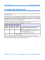
5. ChipworkX On Boot Up
ChipworkX includes three pieces of embedded software, bootstrap loader, TinyBooter and
ChipworkX firmware.
On system boot up, Atmel bootstrap loader initializes Flash and RAM memory then it looks
for the TinyBooter image in the 4MB serial DataFlash chip and lets it execute from RAM.
After TinyBooter takes over the hardware, it prepares the resources to be handled by
ChipworkX firmware. ChipworkX firmware is the main software that runs .NET Micro
Framework core and the user managed application.
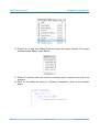
During boot up a user can interrupt the sequence to remain in boot loader, TinyBooter, or
firmware by changing the state of the following signals on start-up:
Pin 133
Pin 127
Pin 129
Up Button
signal
Down Button
signal
Select Button
signal
High or
unconnected
High or
unconnected
High or
unconnected
Low
Low
Low
Low
Low
High or
unconnected
Description
This indicates the user has no interference on boot up
process, and the system will boot in normal mode
sequence.
Hold the system in Flash memory erasing process,
preparing the hardware to be accessed by the bootstrap
loader for TinyBooter update.
Ti nyBooter section provides more details.
Hold the system in TinyBooter mode access
These pins are exposed on ChipworkX Development System to Up, Down and Select
buttons with a high default state. In other words, the pin is low when the button is pressed.
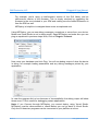
The following flow chart clearly explains the boot up sequence:
Rev.4.3
Page 17 of 51
www.ghielectronics.com
GHI Electronics,LLC
ChipworkX User Manual
ChipworkX On Boot Up
Rev.4.3
Page 18 of 51
www.ghielectronics.com
GHI Electronics,LLC
ChipworkX User Manual
ChipworkX On Boot Up
System Pow er Up
Valid TinyBooter?
TinyBooter needs to be
updated, using TinyBooter
Updater tool
No
Access TinyBooter
Are Up, Dow n and
Select Button signals low ?
(pressed?)
Yes
Are Up and Dow n
button signals low ?
(pressed?)
Yes
Valid Chipw orkX
firmw are(TinyCLR?)
No
Hold the system in
Flash erasing process,
Stay in TinyBooter and w ait
for an action through MFDeploy
tool e.g. Update Chipw orkX firmw are.
Access Chipw orkX firmw are
Valid application code?
No
Stay in EMX firmw are and w ait
for an action through Visual C# or
MFDeploy tool
e.g. Deploy and debug a new
program.
Execute application program
Application program exits
EMX Boot Up Sequence
Flow Chart
Rev.4.3
Page 19 of 51
www.ghielectronics.com
GHI Electronics,LLC
ChipworkX User Manual
ChipworkX On Boot Up
5.1. Bootstrap Loader vs. TinyBooter vs. ChipworkX Firmware
The following table lists the major properties of each software:
Bootstrap Loader
ChipworkX TinyBooter
ChipworkX firmware
Used to update ChipworkX
Used to deploy, execute and
firmware, maintenance
debug the managed NETMF
Used to update ChipworkX application code region, get
application code. In other
TinyBooter
system information and to
words, it plays the role of a
update system configurations
virtual machine.
such as networking settings.
Emergency use or when GHI
frequently used
always used
releases a new TinyBooter.
Pre-placed on the chipset
The user can download to
The user can download to
(provided by Atmel on SAM ChipworkX Module, through ChipworkX Module, through
processors).
GHI boot loader for instance.
TinyBooter for instance.
Latest file is included with
Latest file is included with
Fixed and can not be
every GHI NETMF SDK, not every GHI NETMF SDK, not
updated
necessarily changed in every necessarily changed in every
new SDK
new SDK
Access Interface (debugging Access Interface (debugging
Access interface is USB
interface) can be USB or
interface) can be USB,
(Virtual COM, CDC device).
serial port.
Ethernet or serial port.
Users access it through
Microsoft Visual C# to deploy,
User access is through Atmel
execute and debug the
In-system Programmer
User access it through
managed NETMF application
sam-ba software tool.
MFDeploy tool to maintain
through the debugging
GHI provides simple script
firmware, configurations
interface.
files for easy use of this
(networking, USB) and
Users can access it using
loader to update Tinybooter
application code region.
Microsoft NETMF MFDeploy
tool to maintain the firmware
or application code region.
Highly sophisticated with
Very compact to accomplish
.NET Micro Framework and
Compact enough to handle
only the flash memory
requires HAL and PAL drivers
the assigned functions
maintenance functions.
to provide the various
ChipworkX features.
Next sections provide more details.
Rev.4.3
Page 20 of 51
www.ghielectronics.com
GHI Electronics,LLC
ChipworkX User Manual
ChipworkX On Boot Up
5.2. ChipworkX Access Interface
The default access interface on ChipworkX is USB.
Bootstrap Loader USB driver:
%GHI NETMF SDK%\ChipworkX\Firmware\TinyBooter Updater\USB Tinybooter Updater
driver\ChipworkX-updater.inf
TinyBooter and ChipworkX Firmware USB driver:
%GHI NETMF SDK%\USB Drivers\GHI_NETMF_Interface\GHI_NETMF_Interface.inf
Other Interfaces
You can set other access interfaces and even save them to the device using software.
In case problems occur for the access interface, holding center and down buttons upon
start-up will force ChipworkX to ignore the software settings and use USB interface.
Please see debug interface section for details.
Rev.4.3
Page 21 of 51
www.ghielectronics.com
GHI Electronics,LLC
ChipworkX User Manual
TinyBooter
6. TinyBooter
ChipworkX Module implements a software from Microsoft, called TinyBooter. This software
can be used to update the ChipworkX firmware.
Typically, a user would never need to update TinyBooter as it is not used in the final
application. For rare cases, especially when changing to a different .NET Micro Framework
version -- e.g. 3.0 to 4.0 -- or when it is mentioned in the release notes of a new GHI
NETMF SDK to update the TinyBooter, there is a way to update it through bootstrap
loader.
TinyBooter is loaded from serial DataFlash on power up. On the other hand, TinyCLR is
loaded by TinyBooter from NOR Flash. For compatibility reasons, the user has to erase
both DataFlash and NOR Flash before updating the TinyBooter.
6.1. TinyBooter update using bootstrap loader
The user can update Tinybooter using “Tinybooter Updater” included with GHI NETMF
SDK under ChipworkX\firmware folder. This updater tool consists of Atmel sam-ba tool
with the required script and the BIN file that has to be loaded to serial DataFlash chip. It
also includes the Tinybooter Updater driver that defines USB port as a virtual Serial Port
used to upload the new BIN file through.
The following instructions explain how to successfully accomplish this:
Erasing Process:
1. Power up ChipworkX hardware.
2. Press and hold Up, Select and Down buttons, keep holding and reset the system.
3. Release the buttons when prompted to do so then you will see instructions about how
to proceed.
4. Press Up three times to proceed with the erasing process, or press Down to abort.
Emergency Bootstrap access
Use this method of access whenever something wrong happens during TinyBooter
update process, like uploading the wrong bin file and ChipworkX tinybooter is not
accessible at all.
1. Disconnect power.
2. Remove the jumper placed on ChipworkX Module.
3. Connect power.
Rev.4.3
Page 22 of 51
www.ghielectronics.com
GHI Electronics,LLC
ChipworkX User Manual
TinyBooter
4. Place the jumper back.
5. Connect USB cable.
6. Follow the same next steps for updating the TinyBooter.
Installing TinyBooter Updater USB Driver:
1. After erasing serial DataFlash and NOR Flash successfully following the previous
steps.
2. Power up ChipworkX hardware.
3. Connect USB cable to your PC, then Windows will ask for driver INF file.
4. The driver file is located in the following path:
%GHI NETMF SDK%\ChipworkX\Firmware\TinyBooter Updater\USB Tinybooter Updater Driver\
5. Important Note (for Windows 7 users only): Windows 7 installs the driver
automatically but it mistakenly considers it a GPS camera device. Although the name is
wrong the driver is OK and you may proceed with the steps.
6. After Windows is done installing the driver, you will see a new serial port (COM port) in
your system. It will take the first available COM port number, e.g. COM5.
7. This port is used by TinyBooter Updater script to upload the new tinybooter.bin file to
serial DataFlash, or it can be used to access the processor using Atmel tool SAM-BA
(sam-ba_cdc_2.9.xp_vista.exe) to manually upload bin files to serial DataFlash.
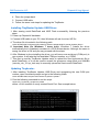
Updating Tinybooter:
1. After installing TinyBooter Updater USB Driver and recognizing the new COM port
number, open command prompt and go to the following folder
%GHI NETMF SDK%\ChipworkX\Firmware\TinyBooter Updater\
2. Run the following command to run the script:
ChipworkX_TinyBooter_Updater.bat COMx
where x is the number of newly created Serial Port. See example below:
Rev.4.3
Page 23 of 51
www.ghielectronics.com
GHI Electronics,LLC
ChipworkX User Manual
TinyBooter
3. When you run the batch file, if you get an Access Denied message from Windows. Try
to run the batch file as an Administrator, or copy the batch file to your desktop and run it
from there.
4. The script will run to upload the new TinyBooter bin file to serial DataFlash. This
process takes several seconds to complete.
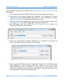
5. When it is done, logfile.log will be created and opened using notepad automatically. It
contains information about the updating process. Make sure the end of the file says
“Sent file & memory area content (....) match exactly!”
The following is an example logfile.log of a successful update:
6. Reset the system and then Tinybooter will execute. Make sure to update TinyCLR
firmware.
7. The system is now ready to deploy new managed applications.
6.2. ChipworkX firmware update through TinyBooter
The objective of this section is to provide simple steps to access TinyBooter on your
ChipworkX-based system from your PC, so you're ready to update ChipworkX firmware
using MFDeploy.
In the following steps, it is assumed that the user is using the USB access interface with
Rev.4.3
Page 24 of 51
www.ghielectronics.com
GHI Electronics,LLC
ChipworkX User Manual
TinyBooter
the GHI NETMF interface driver installed. Refer to ChipworkX access interface section for
more details.
1. First, install the latest GHI NETMF SDK (which includes ChipworkX firmware).
2. Insure there is no need to update the TinyBooter. This information is usually
mentioned in the GHI NETMF SDK release notes. If a new TinyBooter is needed,
update the TinyBooter then update the ChipworkX firmware.
3. Press the Up and Down buttons then reset to set the access interface. Refer to the
ChipworkX on boot up section to learn about the boot up sequence.
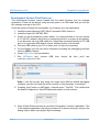
4. Run MFDeploy and select USB from the Device list, you should see
ChipworkX_ChipworkX in the dropdown.
5. Check the communication between MFDeploy and TinyBooter by pinging the
device. Press Ping and you should see this message:
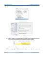
6. Now we can lead MFDeploy to the new ChipworkX firmware files. Click Browse and
direct MFDeploy to the firmware HEX files. These can be found under
ChipworkX\firmware folder in the SDK. The other files with “sig” extension must
exist in the same folder as the HEX files. Select ALL of the HEX files at once and
start deploying the firmware by pressing Deploy.
Rev.4.3
Page 25 of 51
www.ghielectronics.com
GHI Electronics,LLC
ChipworkX User Manual
TinyBooter
7. Loading the files takes about a minute. On completion, the firmware will execute.
Double check the version number to make sure the correct firmware is loaded.
8. Loading new firmware will not erase the deployed managed application. If you need
to erase the managed application, click Erase.
Important Note: After updating the ChipworkX firmware, if you see a message on the
LCD or on ChipworkX access debugging interface stating that you need to update the
TinyBooter, this means that the TinyBooter version is not suitable for the current
firmware. In this case, update the TinyBooter then update ChipworkX firmware again.
Rev.4.3
Page 26 of 51
www.ghielectronics.com
GHI Electronics,LLC
ChipworkX User Manual
ChipworkX Firmware
7. ChipworkX Firmware
ChipworkX firmware is the main piece of embedded software in the ChipworkX Module
which hosts .NET Micro Framework core with the required HAL drivers to provide the
various ChipworkX features a user can control with C#. A user deploys and debugs the
managed application code directly on ChipworkX Module from Microsoft Visual Studio
through ChipworkX debugging interface.
ChipworkX on boot up section provides the required information on how to choose an
access interface and how to access ChipworkX firmware.
ChipworkX firmware is different than TinyBooter or bootstrap loader, Bootstrap loader vs.
TinyBooter vs. ChipworkX firmware section lists the features and properties of each piece
of software.
User can update ChipworkX firmware through TinyBooter. Refer to TinyBooter to learn how
to update the Firmware. ChipworkX firmware can be updated with In-Field Update feature.
The end-user software interface that communicates with ChipworkX firmware is MFDeploy,
which comes with Microsoft .NET Micro Framework SDK and Microsoft Visual C# with
installed .NET Micro Framework SDK.
7.1. Getting Started with ChipworkX
The objectives of this section are to provide simple steps to setup your ChipworkX-based
system on your PC, so you're ready to develop your application on Visual Studio C#
with .NET Micro Framework.
All you need to start up
●
ChipworkX Development System.
●
USB Cable (included with the kit).
●
Microsoft Visual Studio 2010 or Microsoft Visual C# Express Edition (free download)
installed with latest updates.
●
Microsoft .NET Micro Framework SDK Version 4.1.
●
Latest GHI NETMF SDK, available on GHI Electronics website.
If you got a new ChipworkX Development System, it is recommended that you update
ChipworkX firmware and TinyBooter if needed, with the files available in the latest GHI
NETMF SDK within ChipworkX folder before you start these steps.
The suggested access interface in these steps is USB (the default on ChipworkX
Development System).
Rev.4.3
Page 27 of 51
www.ghielectronics.com
GHI Electronics,LLC
ChipworkX User Manual
ChipworkX Firmware
Development System First Power-up
The development system comes loaded with the latest firmware and an example
application. Power up the device using a power pack or a USB cable and you will see
the example running on the LCD.
Once the system is tested for functionality, try to deploy your own application.
1. Install the latest Microsoft .NET Micro Framework SDK Version 4.
2. Install the latest GHI NETMF SDK
3. Power up the development system board. It is recommended to use any regular
9~15 Volt DC adapter, with the inner connector positive, to power-up the system.
It can be power up over USB cable but it should be connected directly to PC USB
port or to a powered USB hub to ensure sufficient power for the board.
4. Connect USB cable to your PC on other end, if it was not connected.
5. On the Display you will see some information including the debugging interface
which is USB by default.
6. Install USB driver if not yet installed.
7. Run
MFDeploy
tool, choose
ChipworkX_ChipworkX in list.
USB
from
device
list
then
you'll
see
Note: if you did not see that string you might have different default debugging
interface, you did not install the driver correctly, or the processor is shutdown.
8. Pressing “ping” button on MFDeploy. It should return “TinyCLR”. This verifies that
the board is responsive. See MFDeploy description in next sections.
9. Open Visual Studio and start a new Micro Framework “console” application. This
is the simplest application that can be loaded. All it does is printing a string to the
debug output. Name your project MyConsoleApp
Rev.4.3
Page 28 of 51
www.ghielectronics.com
GHI Electronics,LLC
ChipworkX User Manual
ChipworkX Firmware
10. Visual Studio will now generate all needed project files. One of the files is called
Program.cs. Open it...
11. Place a breakpoint at Debug.Print line. You can do this by clicking on the line and
then pressing F9.
12. Compile the application. There should be no errors.
13. Go to the menu and select Project > MyConsoleApp Properties... and in the
new window select the Micro Framework tab. In the tab, there are options for
deployment. Select USB for transport and select ChipworkX_ChipworkX .
Rev.4.3
Page 29 of 51
www.ghielectronics.com
GHI Electronics,LLC
ChipworkX User Manual
ChipworkX Firmware
14. Press F5 (Debug). You will see how Visual Studio loads the application and runs
it. Visual Studio should pause at the breakpoint we placed in step 4.
15. Make sure you have the output window open. If not, open the window by
selecting View > Output.
Rev.4.3
Page 30 of 51
www.ghielectronics.com
GHI Electronics,LLC
ChipworkX User Manual
ChipworkX Firmware
16. Press F10 to step over Debug.Print and watch the output window. The output
window should display “Hello World!”
17. Press F5 and the code will continue executing until it reaches the end of the
program.
18. Now, try to modify the string to “Amazing Framework!” and run the program
again.
Rev.4.3
Page 31 of 51
www.ghielectronics.com
GHI Electronics,LLC
ChipworkX User Manual
ChipworkX Firmware
Adding GHI NETMF Library
1. Go to the Project tab and click Add Reference.
2. Let's add USB Host library. Select it and click OK.
3. Add "using" for the name space at the beginning of the file:
using GHIElectronics.NETMF.USBHost;
4. As an example, we will get a list of currently connected devices. Add this in Main()
method:
USBH_Device[] devices = USBHostController.GetDevices();
5. Similarly, you can use any other functionality provided by GHI library. Press F5 in
visual studio and the program will run.
If the program does not run, then there is something incompatible on your system.
Rev.4.3
Page 32 of 51
www.ghielectronics.com
GHI Electronics,LLC
ChipworkX User Manual
ChipworkX Firmware
For example, you're using a new/incorrect version of the GHI library and an
old/incorrect version of the firmware. This is simply resolved by upgrading the
firmware to the one included in your SDK and making sure the Added Reference is
from the SDK as well.
MFDeploy is helpful to investigate these errors as explained next.
Using MFDeploy, you can see debug messages, exceptions or errors from your device.
Make sure Visual Studio is not in debug mode. Open MFDeploy and make sure you can
ping as explained in previous steps. Now, Click on Target > Connect.
Now, reset your hardware and click Ping. You will see debug output of what the device
is doing, for example loading assemblies and any debug messages printed by your
application.
In case the program did not run because of incompatibility, the debug output will show
these errors. This is useful for debugging certain applications.
Note: If you Connect through MFDeploy, you cannot deploy using Visual Studio.
MFDeploy must be disconnected or closed before you can go back to Visual Studio.
Only one of these two programs can be connected to your platform at a time.
Rev.4.3
Page 33 of 51
www.ghielectronics.com
GHI Electronics,LLC
ChipworkX User Manual
ChipworkX Firmware
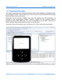
7.2. ChipworkX Emulator
.NET Micro Framework has a powerful emulator that can be extended or changed to suite
the developer's needs. This is useful as you can do most of the development and testing
before building the actual hardware.
ChipworkX has an emulator available that maps the buttons and LCD dimensions as
provided on the Development System. However, support for the extended features
provided by GHI (PWM, USB Host, etc.) are not supported in the emulator. Using any of
these extended features will result in an error on the emulator.
A user can choose the emulator from the Device list in Visual studio project properties.
Rev.4.3
Page 34 of 51
www.ghielectronics.com
GHI Electronics,LLC
ChipworkX User Manual
ChipworkX Features
8. ChipworkX Features
ChipworkX supports all of the necessary features of .NET Micro Framework with the
required HAL and PAL drivers such as Graphics, TCP/IP, SSL and FAT File System. .NET
Micro Framework SDK includes full documentation and examples about the usage of
these features with the related libraries.
Furthermore, ChipworkX supports other exclusive GHI hardware and software features
such as USB host, PPP, GPRS/3G, Database, RLP and Internal FAT storage. GHI NETMF
SDK includes the required library files with full documentation and examples about the
usage of these features with the related libraries.
The following sections clarify necessary guidelines about ChipworkX features.
8.1. Application Flash/RAM/EWR
8MB of external flash is available on ChipworkX Modules. External flash is used for
firmware, system assemblies, user deployment and EWR storage.
64MB of SDRAM comes standard with ChipworkX Module. Enough for applications
using .NET Micro Framework and SideShow.
Extended Week References (EWR)
EWR (Extended Week References) is a way for managed applications to store data on
FLASH memory. Stored data has priorities, if more data needs to be stored and the
flash EWR region is full, some lower priority data will be overwritten. Consult .NET Micro
Framework documentation for more details.
If more storage is needed, Internal 256MB Flash, SD memory cards and/or USB
memory devices can be used. EWRs do not work with removable media devices.
NAND Flash
256MB of NAND flash is used as FAT file system storage under .NET Micro Framework.
It can be accessed just like any other media, SD card or USB storage device.
8.2. Debugging Interface (Access Interface)
Access Interface with ChipworkX firmware is usually named NETMF debugging interface
which is the communication interface between ChipworkX firmware and the application
code terminal (Visual C# debugger). It can be configured as USB, serial port or Ethernet.
Access Interface section provides the required information on how to access ChipworkX
debugging interface.
Rev.4.3
Page 35 of 51
www.ghielectronics.com
GHI Electronics,LLC
ChipworkX User Manual
ChipworkX Features
Changing the debug interface might be necessary for some applications. The default
debug interface is USB, but some application might need to use the USB Client feature to
connect to PC as a different device, for example a USB Storage. In this case, you should
change the debug interface.
Other access interfaces can be enabled using software. Using GHI library, you can set the
interface and it is saved. So, it will keep this setting after you reset the device. Only
TinyCLR (Firmware) and TinyBooter interfaces can be changed. The Bootloader cannot be
changed using software.
You can force ChipworkX to ignore the software settings and use the default USB
interface. This is helpful in case the incorrect settings are stored. This is done by holding
Center and Down buttons upon startup.
If you are not able to access the device after setting the debug interface, for example it
was set incorrectly, you can reboot the device in bootloader mode, erase and update
TinyBooter and firmware again.
Software settings is done using GHI NETMF library under:
GHIElectronics.NETMF.Hardware.Configuration
8.3. Digital Inputs/Outputs
The module has 80 digital I/O pins that can be used in managed applications. All digital I/O
pins are 3.3V only. This means that signals coming from another circuit can NOT be higher
than 3.6V. All pins support input and output with pull-up feature.
All digital I/O pins are interrupt capable. Interrupt pins asynchronously call functions in
managed applications. Interrupts can be activated on rising or falling edges with optional
glitch filter. Enabling interrupts for both rising and falling edges is supported but in this
case the glitch filter is disabled.
Refer to the Pin-Out Description section for more information about Digital I/O assignment
to ChipworkX hardware pins.
The I/Os are numbered as in the following table:
Rev.4.3
AT91SAM9261S Peripheral IO
ChipworkX
Port Name
Pin name
IO number
PA
PA0...PA31
0..31
PB
PB0...PB31
32..63
PC
PC0...PB31
64..95
Page 36 of 51
www.ghielectronics.com
GHI Electronics,LLC
ChipworkX User Manual
ChipworkX Features
8.4. Serial Peripherals
Serial Port (UART)
One of the oldest and most common protocols is UART (or USART). ChipworkX
hardware exposes three UART ports
Serial Port AT91SAM9261S UART
Hardware Handshaking
COM1
Debug Unit DBGU
Not Supported
COM2
USART0
Not Supported
COM3
USART2
Supported
Important Note: Serial port pins have 3.3V TTL levels where the PC uses RS232
levels. For proper communication with RS232 serial ports (PC serial port), an RS232
level converter is required. One common converter is MAX232.
Note: If the serial port is connected between two TTL circuits, no level converter is
needed but they should be connected as a null modem. Null modem means RX on one
circuit is connected to TX on the other circuit, and vice versa.
Refer to the Pin-Out Description section for more information about UART signals
assignment to ChipworkX hardware pins.
SPI
ChipworkX supports two SPI Interfaces SPI1 and SPI2. SPI Bus is designed to interface
multiple SPI slave devices, the active slave is selected by asserting Chip Select line on
the relative slave device.
SPI1 is used to interface the touch screen controller, MS1053 codec and SD card.
Therefore, if the developer is using an additional SPI slave device through SPI1, this
device must use SPI bus only when its chip select signal is active and that could be
accomplished by dedicating one of the Digital I/Os to do this function in SPI
configuration ChipSelect_Port.
A good example is reading analog inputs of the touch screen controller and to control
VS1053 MP3 decoder chip on the development System. Example project source code
included in GHI NETMF SDK is a good reference on how to do so.
IMPORTANT NOTE: ChipworkX module uses SPI-based flash for bootstrap. This flash
is connected to SPI1 bus, SPI2 is completely free. A SPI bus master (ChipworkX) is
designed to work with multiple slaves. For example, ChipworkX Development System
uses SPI1 for flash, touch screen controller and MP3 decoder chip. Our WiFi module
uses SPI1 as well by default. They all work in sync because only one slave is selected
at any time. This is accomplished by passing the Chip Select pin along with SPI
configurations so the pin is selected only when data is being sent and then it is
automatically deselected.
Rev.4.3
Page 37 of 51
www.ghielectronics.com
GHI Electronics,LLC
ChipworkX User Manual
ChipworkX Features
If you are not sure of how SPI works or your slave cannot be deselected (doesn't have
Chip Select pin, SSEL) then you must use SPI2, which is completely free.
This applies to all SPI1 bus pins. Those are SPI1-MOSI, SPI1-MISO, SPI1-SCK.
Ideally, SPI1 can only be used when a developer has already used all pins and must
use SPI1; otherwise, SPI1 pins should be left unused by the developer.
Refer to the Pin-Out Description section for more information about SPI signals
assignments to ChipworkX hardware pins.
I2C
I2C is a two-wire addressable serial interface. ChipworkX supports one master I2C port.
Refer to the Pin-Out Description section for more information about I2C signals
assignments to ChipworkX hardware pins.
I2C on ChipworkX is implemented using sofware. Users should note these few points:
1. I2C blocks managed threads. It is recommended to use small data chucks.
2. The I2C clock rate is not accurate but this should not affect the I2C functionality. For
example, using 100Khz for clock will result in 70Khz.
3. Losing Arbitration is not supported.
4. Read and Write timeouts are not supported.
5. Using buses like SPI and UART is recommended over I2C.
One-wire Interface
Through one-wire, a master can communicate with multiple slaves using a single digital
pin. One-wire can be activated on any Digital I/O on ChipworkX.
This is available through GHI NETMF library.
8.5. Networking (TCP/IP)
Networking is a crucial part in today's embedded devices. .NET Micro Framework includes
a full TCP/IP stack with complete socket support for manged applications. ChipworkX
networking implementation includes PPP, WiFi, Ethernet, TCP/IP, SSL, HTTP, and Device
Profile for Web Services.
MAC address setting
User can use MFDeploy to update the correct MAC address before the device is
connected to a network. Network settings can also be changed dynamically from the
managed code.
Rev.4.3
Page 38 of 51
www.ghielectronics.com
GHI Electronics,LLC
ChipworkX User Manual
ChipworkX Features
NetworkInterface[] netif = NetworkInterface.GetAllNetworkInterfaces();
// Set new MAC address
byte[] newMAC = new byte[] { 0x00, 0x1A, 0xF1, 0x01, 0x42, 0xDD };
netif[0].PhysicalAddress = newMAC;
IP address (DHCP or static):
DHCP (dynamic) IP and Static IP are supported when using Ethernet or WiFi on
ChipworkX. If using dynamic IP, ChipworkX will not obtain IP lease at power up. DHCP
can only be enabled from software. MFDeploy has a DHCP enable option but it has not
effect on getting the IP lease on startup.
NetworkInterface[] netif = NetworkInterface.GetAllNetworkInterfaces();
// Get an IP address from DHCP server
if (netif[0].IsDhcpEnabled)
{
netif[0].RenewDhcpLease();
}
else
{
netif[0].EnableDhcp();
}
Ethernet
ChipworkX Module includes a 10/100 base PHY DM9000 with all required circuitry.
Users who wish to use Ethernet have to add an Ethernet connector with magnetic such
as J0026D21 or any other compatible connectors.
Refer to the Pin-Out Description section for more information about Ethernet signals
assignments to ChipworkX hardware pins.
GHI Electronics supplies a dedicated MAC address for each ChipworkX Module. The
address can be found on a sticker on the module.
Rev.4.3
Page 39 of 51
www.ghielectronics.com
GHI Electronics,LLC
ChipworkX User Manual
ChipworkX Features
Wireless LAN WiFi (IEEE 802.11b)
ChipworkX includes drivers for ZeroG ZG2100/ZG2101 SMT modules. Which are SPI
bus-based, low-priced and FCC certified. The only difference between ZG2100 and
ZG2101 is that ZG2100 hosts an on-board antenna and ZG2101 includes a connection
for an external antenna.
Note: The MAC address is available on the SMT module.
ZG2100 module front view
ZG2100 module back view
GHI Electronics LLC is an ZeroG authorized design partner:
To get started with ZeroG WiFi modules on ChipworkX, GHI Electronics offers NETMF
WiFi expansion that hosts ZeroG ZG2100 module. and can be easily plugged in
ChipworkX,ChipworkX or EMX development system.
http://www.ghielectronics.com/product/126
Rev.4.3
Page 40 of 51
www.ghielectronics.com
GHI Electronics,LLC
ChipworkX User Manual
ChipworkX Features
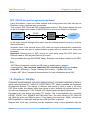
PPP (TCP/IP access through serial modems)
Using this feature, users can create sockets and communicate over links that are not
Ethernet, serial or wireless links for example.
This includes PPP Client with PAP authentication protocol. This feature allows the user
to dial in through serial modem (V.90/GPRS/3G) to access the Internet or Extranet.
Embedded
Master
PPP Client
TCP/IP
Serial Communication
Serial
Modem
Internet
In this case, network settings will be taken from the hosting terminal server (e.g. Internet
Service Provider).
Important Note: If the terminal server (ISP) does not require authentication credentials,
a user must use this type of communication anyway with any random user name and
password.
Important: Ethernet port or WiFi cannot be used when using GHI PPP Stack. but
Ethernet cable or WiFi physical link can be traced.
This is available through GHI NETMF library. Example code is also included in the SDK.
SSL
.NET Micro Framework includes an SSL stack to enable secure network
communication. The user must update the SSL seed through MFDeploy before
using SSL, MFDeploy > Target > Manage Device Keys > Update SSL Seed.
Consult .NET Micro Framework documentation for more information about SSL.
8.6. Graphics / Display
ChipworkX Module supports 16bit color displays natively. The default resolution is 480x272
which matches Sharp 4.3” (480x272) LQ043T1DG01 TFT display available on ChipworkX
Development System. This display is common and similar to what is used in the Sony
PSP. What makes this display better than others is that it embeds all required circuitry to
run with only supplying 5V, 3.3V, Ground, LCD digital signals and back light power.
Developers can use almost any digital TFT display. This is accomplished by connecting
HSYNC, VSYNC, CLK, ENABLE and 16Bit color lines. The color format is 5:6:5 (5Bits for
red, 6Bits for green and 5Bits for blue). If the display has more than 16Bits, connect the
MSB (high Bits) to ChipworkX and the extra LSB (low Bits) to ground.
Displays with VGA input (monitors) can be supported using a frame generator chip like
Rev.4.3
Page 41 of 51
www.ghielectronics.com
GHI Electronics,LLC
ChipworkX User Manual
ChipworkX Features
Chrontel's CH7025 to convert LCD signals into VGA analog signals with the suitable
timing.
Currently the highest supported resolution is 800x600. If your application requires a higher
resolution, please contact us.
Refer to the ChipworkX Development System schematic for more information about
hardware design (Back Light circuit, TFT signal connections).
Refer to the Pin-Out Description section for more information about TFT signals
assignments to ChipworkX hardware pins.
With ChipworkX graphics support, users can leverage .NET Micro Framework graphics
features such as:
•
Windows Presentation Foundation (WPF)
•
BMP, GIF and JPEG image files.
Consult .NET Micro Framework documentation for more information on graphics support.
Developer can either use the same TFT display or other ones. This can be achieved by
customizing the LCD controller registers to match the requirement of the new LCD.
Displays with VGA input (monitors) can be supported using a frame generator chip to
convert LCD signals into VGA analog signals with the suitable timing.
For more information about LCD controller registers refer to AT91SAM9261S User
Manual.
8.7. PWM
ChipworkX hardware includes a PWM output which is mainly utilized to control the LCD
back light illumination.
This is available through GHI NETMF library.
8.8. Touch Screen Control
By default, ChipworkX supports touch screen using the TSC2046 touch controller chip with
two analog inputs which are used to access the touch screen which is controlled though
SPI1.
Developers can support different kinds of touch screens and touch controllers easily by
writing a simple driver and exposing the position parameters to touch screen methods.
Refer to the Pin-Out Description section and ChipworkX Development System schematic
for more information about touch screen controller TSC2046 connections signals.
Rev.4.3
Page 42 of 51
www.ghielectronics.com
GHI Electronics,LLC
ChipworkX User Manual
ChipworkX Features
8.9. USB Device (Client)
USB Client (device) and USB Host are completely different. Many designers confuse USB when it comes
to host and device. USB Host is the master of the bus where all the work is done. USB devices are simple
compared to host and they can only connect/communicate with a host and not other devices. USB host and
device on ChipworkX are two separate peripherals, so there would be no conflict when using them both
simultaneously.
The USB client interface is usually used as an ChipworkX access interface for debugging
and application deployment through Microsoft Visual Studio. However, developers have
full control over the USB client interface. For example, the USB client can be made to
simulate a USB keyboard or USB mass storage.
Controlling a ChipworkX USB client requires intricate knowledge of how USB works. The
user should refer to .NET Micro Framework documentation for complete details on how to
use this feature.
Fortunately, GHI Electronics offers a USB Client library (available in the SDK) to ease
development and provide direct support for some USB devices, such as, Mass Storage
(Virtual Disk) and CDC (Virtual COM Port). The library is capable of creating a USB client
that's composed of multiple USB interfaces. Please refer to GHI NETMF Library for more
information.
ChipworkX Module contains USB host and USB client (both can work simultaneously).
Refer to the Pin-Out Description section for more information about USB device signals
assignment to ChipworkX hardware pins.
Important Notes:
•
Be CAREFUL when changing the USB configuration and settings, as you go on
with development and creating your USB device and connecting it to the PC,
Windows might save the device information in its registry. Therefore, if you change
the USB device settings/interfaces and connect it again, it might not work correctly.
Make sure to be careful with changing your USB device settings. You may also
need to delete all the settings from Windows registry manually.
•
By default, Micro Framework debug interface is USB. If you need to use the USB
Client feature to build a USB device, you should select a different debug interface
first (COM1).
USB cable connection detection
USB VBUS (USB power) can be connected, through a protection resistor, to any digital
I/O to detect the presence of a USB cable.
Rev.4.3
Page 43 of 51
www.ghielectronics.com
GHI Electronics,LLC
ChipworkX User Manual
ChipworkX Features
8.10. USB Host and Supported USB Drivers
USB Client (device) and USB Host are completely different. Many designers confuse USB when it comes
to host and device. USB Host is the master of the bus where all the work is done. USB devices are simple
compared to host and they can only connect/communicate with a host and not other devices. USB host and
device on ChipworkX are two separate peripherals, so there would be no conflict when using them both
simultaneously.
USB Host allows the use of USB Hubs, USB storage devices, joysticks, keyboards, mice,
printers and more. With ChipworkX supported class drivers, you don't have to worry about
the inner workings. For USB devices that do not have a standard class, low level USB
access is supported. ChipworkX Module contains USB host with two ports and USB client
(both can work simultaneously).
Refer to the Pin-Out Description section for more information about USB Host signals
assignment to ChipworkX hardware pins.
This is available through GHI NETMF library.
8.11. Storage Devices (Internal Flash, SD, USB) / File System
File System lets you create and manipulate files and folders on the connected SD and
USB storage devices.
With .NET Micro Framework V4.0, FAT32 and FAT16 are supported by NETMF. The user
should refer to .NET Micro Framework documentation for details on handling files and
folders.
Note: FAT32 and FAT16 formats are supported, but FAT12 is not. You can format your
storage device on a PC with a FAT32 or FAT16 option before using on ChipworkX.
Before using the storage devices and accessing them with NETMF, the user must mount
the file system first. This is done using the ChipworkX library provided with the SDK. SD
cards and USB storage devices are NOT mounted automatically.
Please refer to library documentation: GHIElectronics.NETMF.IO.PersistentStorage
Internal Flash Storage
ChipworkX Hardware has 256MB NAND Flash which is utilized as file storage with FAT
file system. The NAND is used only for File System operations were sector failure will
not cause the system to be unstable. NAND flash devices have a limited life span on
how many erases can be done on one sector. This should not be a problem for many
applications as the limits are 100,000 erase cycles minimum. Also, with wear leveling
support, this will dramatically increase the NAND life span.
SD/MMC Memory
SD and MMC memory cards have a very similar interface. ChipworkX Module supports
Rev.4.3
Page 44 of 51
www.ghielectronics.com
GHI Electronics,LLC
ChipworkX User Manual
ChipworkX Features
both cards and also supports SDHC (over 4GB) cards. ChipworkX uses SPI1 to access
SD/MMC cards and PA4 Digital I/O for chip select signal. There are two smaller
versions of SD cards, mini SD and micro SD. All card sizes are identical as far as the
interface. The only difference is the physical dimensions.
A user may be interested in mounting or unmounting the file system on the SD card
automatically when a SD card is inserted or ejected. To do this, there is a pin on the SD
card connector called Card Detect which works like a switch. Connect this to a GPIO
InterruptPort on ChipworkX and call mount, unmount appropriately.
USB Memory
Before proceeding, make sure you have an understanding of how USB devices are
inserted and detected on your .NET Micro Framework device. Refer to the USB Host
section.
Similar to SD cards, the user may be interested in mounting/unmounting the file system
on the USB drive automatically when a USB drive is inserted or ejected. To do this, you
can get events from ChipworkX about connection/disconnection of USB devices and
call mount, unmount appropriately.
8.12. Output Compare
Using output compare developers can generate different waveforms. This is available on
any digital output pin.
This is available through GHI NETMF library.
8.13. Database
ChipworkX supports SQLite which is useful for logging and retrieving data using standard
SQL queries. A database can be created in RAM or saved on Storage Media with file
system (SD,NAND or USB mass storage). Refer to ChipworkX.Database for reference on
creating databases in RAM or non-volatile memory.
GHI NETMF SDK includes a simple example code on how to use the database feature.
8.14. Power Control / Hibernate
Power Control
ChipworkX is running at 200MHz. However, the user can, using register access, change
the clock speed. This way, the processor will run slower and consume less power.
Hibernate
The user can put ChipworkX in hibernate mode through PowerState functionality in
Rev.4.3
Page 45 of 51
www.ghielectronics.com
GHI Electronics,LLC
ChipworkX User Manual
ChipworkX Features
Micro Framework. Only “DeepSleep” mode is supported. In this mode, the processor is
set into idle wait-for-interrupt mode in which the clock to the ARM core stops, reducing
the power used when the processor is not busy. Note that the rest of the device is still
clocked by the master clock. If needed, clocks of the unused peripherals can be
deactivated (through register access) to participate in power saving.
Here's an example to sleep and then wake up on an interrupt pin:
// Must enable an interrupt event on the user "wake up" pin.
InterruptPort wakeUpPin = new InterruptPort(ChipworkX.Pin.PA25, false,
Port.ResistorMode.PullUp, Port.InterruptMode.InterruptEdgeBoth);
wakeUpPin.OnInterrupt += new NativeEventHandler(wakeUpPin_OnInterrupt);
// Sleep. Specify waking up on GeneralPurpose IO
PowerState.Sleep(SleepLevel.DeepSleep, HardwareEvent.GeneralPurpose);
8.15. Real Time Clock
AT91SAM9261S includes a real-time clock that can operate while the processor is off. The
developer only needs to wire a 3V battery or a super capacitor to the VBAT pin. A 32KHz
crystal is already included in the ChipworkX module.
This is available through GHI NETMF library.
8.16. Battery RAM
There are 16 Bytes of RAM that is backed-up by battery. Data is retained on power loss.
The developer only needs to wire a 3V battery or a super capacitor to the VBAT pin.
This is available through GHI NETMF library.
8.17. Processor Register Access
ChipworkX Module allows direct access to the AT91SAM9261S registers. The user can
write, read or manipulate the bits as needed. This can be useful, enabling some features
that may not be already exposed.
This is available through GHI NETMF library.
8.18. JTAG access
ChipworkX hardware exposes JTAG which can be used to download different firmware or
to debug user defined native code (Runtime Loadable Procedure code).
8.19. Runtime Loadable Procedure RLP
A highly useful and unique feature in ChipworkX is allowing users to load their own
compiled native code (C or assembly) and run it directly through managed code. This
feature is similar to the use of DLLs on PCs. RLP can be used to implement processing
Rev.4.3
Page 46 of 51
www.ghielectronics.com
GHI Electronics,LLC
ChipworkX User Manual
ChipworkX Features
intensive and time-critical routines.
This is available through GHI NETMF library.
8.20. In-Field Update
This functionality allows devices that are deployed in the field to update their software
automatically without external help. This is very useful in remote and end users'
applications.
You can update the managed application only or the entire device (including GHI firmware
files). Also, this feature includes a managed C# bootloader that the user will provide. This
is different from the GHI low level bootloader that already exists on the device.
This is available through GHI NETMF library.
8.21. Watchdog
Watchdog is used to reset the system if it enters an erroneous state. The Watchdog is
enabled with a specified timeout. The user must keep resetting the Watchdog time counter
within this timeout interval or otherwise the system will reset.
This is available through GHI NETMF library.
Rev.4.3
Page 47 of 51
www.ghielectronics.com
GHI Electronics,LLC
ChipworkX User Manual
Advanced Users
9. Advanced Users
ChipworkX Module is based on the Atmel AT91SAM9261S microcontroller. With
ChipworkX firmware's register access feature, advanced users familiar with this
microcontroller, can manipulate the internal registers.
10. ChipworkX Design Consideration
10.1. Hardware
The following peripherals are recommended to be exposed from the module in any design,
possibly hidden from the end user:
•
Up, Down and Select button pins.
•
USB Device (Client).
IMPORTANT NOTE: ChipworkX module uses SPI-based flash for bootstrap. This flash is
connected to SPI1 bus, SPI2 is completely free. A SPI bus master (ChipworkX) is
designed to work with multiple slaves. For example, ChipworkX Development System uses
SPI1 for flash, touch screen controller and MP3 decoder chip. Our WiFi module uses SPI1
as well by default. They all work in sync because only one slave is selected at any time.
This is accomplished by passing the Chip Select pin along with SPI configurations so the
pin is selected only when data is being sent and then it is automatically deselected.
If you are not sure of how SPI works or your slave cannot be deselected (doesn't have
Chip Select pin, SSEL) then you must use SPI2, which is completely free.
This applies to all SPI1 bus pins. Those are SPI1-MOSI, SPI1-MISO, SPI1-SCK.
Ideally, SPI1 can only be used when a developer has already used all pins and must use
SPI1; otherwise, SPI1 pins should be left unused by the developer.
10.2. Software
ChipworkX firmware is only licensed to work on ChipworkX MINI9261I modules provided
by GHI Electronics, LLC. Please consult GHI Electronics for customized firmware for other
hardware designs.
Rev.4.3
Page 48 of 51
www.ghielectronics.com
GHI Electronics,LLC
ChipworkX User Manual
ChipworkX design Consideration
10.3. ChipworkX Placement
ChipworkX Module MINI9261I mounting is a standard SO-DIMM 200-pin.
A compatible SO-DIMM 200-pin connector is 1565917-4 from AMP.
Rev.4.3
Page 49 of 51
www.ghielectronics.com
GHI Electronics,LLC
ChipworkX User Manual
Appendix A: MFDeploy Tool
Appendix A: MFDeploy Tool
MFDeploy is a free tool from Microsoft that helps you deploy
Microsoft .NET Micro Framework applications to your hardware
devices. MFDeploy makes it easy for you to download the
firmware you are developing to your hardware. MFDeploy is
available in NETMF SDK. %Microsoft .NET Micro
Framework\vx.0 folder%\Tools\MFDeploy.exe
Detailed documentation about MFDeploy is available under .NET Micro Framework Help.
One of the great features of MFDeploy is authenticating loaded files. MFDeploy uses
public/private keys to verify files. This is a good feature for companies who want to make
sure they are the only ones who can load applications on the system. MFDeploy
documentation explains this feature in details.
Rev.4.3
Page 50 of 51
www.ghielectronics.com
GHI Electronics,LLC
ChipworkX User Manual
Legal Notice
Legal Notice
Licensing
ChipworkX Module is fully licensed for commercial use. The Module price covers the
commercial use of ChipworkX Module with .NET Micro Framework.
Disclaimer
IN NO EVENT SHALL GHI ELECTRONICS, LLC. OR ITS CONTRIBUTORS BE LIABLE FOR ANY
DIRECT, INDIRECT, INCIDENTAL, SPECIAL, EXEMPLARY, OR CONSEQUENTIAL DAMAGES
(INCLUDING, BUT NOT LIMITED TO, PROCUREMENT OF SUBSTITUTE GOODS OR SERVICES; LOSS
OF USE, DATA, OR PROFITS; OR BUSINESS INTERRUPTION) HOWEVER CAUSED AND ON ANY
THEORY OF LIABILITY, WHETHER IN CONTRACT, STRICT LIABILITY, OR TORT (INCLUDING
NEGLIGENCE OR OTHERWISE) ARISING IN ANY WAY OUT OF THE USE OF THIS PRODUCT, EVEN
IF ADVISED OF THE POSSIBILITY OF SUCH DAMAGE. SPECIFICATIONS ARE SUBJECT TO CHANGE
WITHOUT ANY NOTICE. GHI ELECTRONICS, LLC LINE OF PRODUCTS ARE NOT DESIGNED FOR
LIFE SUPPORT APPLICATIONS.
ChipworkX is a Trademark of GHI Electronics, LLC
.NET Micro Framework, Visual Studio, MFDeploy, Windows Vista, Windows SideShow are registered or
unregistered trademarks of Microsoft Corporation.
Other Trademarks and Registered Trademarks are Owned by their Respective Companies.
Rev.4.3
Page 51 of 51
www.ghielectronics.com