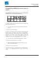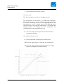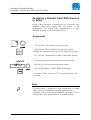
1
zirkon / zirkon XL
User manual
Release:
Ausgabe:
2.5
2005-11-08
interstage
Phistersvej 31, 2900 Hellerup, Danmark
Telefon 3946 0000, fax 3946 0040
www.interstage.dk
- pro audio with a smile
Copyright
All rights reserved. Permission to reprint or electronically reproduce any document or
graphic in whole or in part for any reason is expressly prohibited, unless prior written
consent is obtained from the Lawo AG.
All trademarks and registered trademarks belong to their respective owners. It cannot be
guaranteed that all product names, products, trademarks, requisitions, regulations,
guidelines, specifications and norms are free from trade mark rights of third parties.
All entries in this document have been thoroughly checked; however no guarantee for
correctness can be given. Lawo AG cannot be held responsible for any misleading or
incorrect information provided throughout this manual.
Lawo AG reserves the right to change specifications at any time without notice.
© Lawo AG, 2005
Contents
Contents
CONTENTS
PREFACE
Manual Structure
Typographical Markers
Conventions of the Notes
WARNING NOTES
INTRODUCTION: THE ZIRKON SYSTEM
Features of the zirkon system
Components of the zirkon system
System block diagram
CONTROL ELEMENTS, WHAT IS WHERE?
Channel module
Central module
zirkonXL Central Module
OPERATING CONCEPT
Basic operating concept
Channel module
Central module
Assigning a channel strip with sources
Summing bus assignment
Audiocontrol
Pre-amplification (GAIN) mono sources
Pre-amplifying (GAIN) line sources stereo in general
Pre-Amplification (GAIN) Microphone sources stereo
Equalizer
Dynamics section (dyn)
Limiter (lim)
Insert
Delay
Saving of configurations, PFL
Preparing the Chipcard for Save and Load
Storing a setup
Loading a Setup
Internal Saving of a Setup
Deleting a Setup
Loading a Setup
PFL mode
OPERATING CONCEPT ZIRKONXL
zirkon / zirkon XL User manual
Release 2.5
3
7
7
9
10
11
15
15
16
17
19
19
21
22
25
25
25
26
27
28
29
30
33
34
34
36
39
39
41
41
43
43
44
44
46
46
48
50
Contents
Basic operating concept
Channel module
Central module
Assigning a Channel Strip With Sources or Sums
Assignment
Removing a Source from the Channel Strip
Alternative Method of Channel Access
Summing Bus Assignment
Simple Bus Assignment
Bus Assignment with SEND Gain
Bus Assignment on the Channel Strip
Audio Control
GAIN Mono Source Line
GAIN Line Source Stereo
GAIN Mono Source Microphone
Gain Stereo Source Microphone
Equalizer
DYN
Limiter
Insert
Delay
Saving and Loading of Setups
Saving of Internal Snapshots
Loading of Internal Snapshots
Saving of Snapshots on Compact Flash Cards
Loading Snapshots from the Compact Flash Card
Setting Up the PFL Mode
Radio automation
MAINTENANCE AND SERVICE
System page (http:// )
DSP card information
Sync Information
Slot Information
Panel Information
Supplementary Information
Server Connections
Client Connections
Control Panel Modules: Configuring and Testing
Channel module 950/41:
CAN SPEED
FADER KAL
TESTS
POWER TEST
Release 2.5
50
50
51
52
52
53
53
53
53
54
55
56
57
58
60
61
61
64
68
70
72
72
73
73
74
76
77
78
79
79
80
81
81
81
81
81
81
82
82
83
83
85
85
zirkon / zirkon XL User manual
Contents
KEY TEST
SELF TEST
Central module 950/42:
CAN SPEED
POTI KAL
KEY TEST
SELF TEST
POWER TEST
950/46 zirkonXL Central Unit
Version Query Software
Self Test
Key Test
Calibrating Fader and Potentiometers
Changing the CAN Speed
950/50 Key20, 950/51 TB12 and 950/53 Key20 Desktop
Activating the Servicemode
Lamp Test
Button Test
Cleaning the operating surface
Replacing the lithium battery
Defective modules
ACCESSORIES
Power supply unit for console modules
Redundant PSU for the system unit
19” Push button module (KS16)
GLOSSARY
zirkon / zirkon XL User manual
Release 2.5
85
87
88
89
90
91
91
91
93
93
93
94
96
98
99
100
100
100
101
101
102
103
103
103
103
105
Warning Notes
Features of the zirkon system
Preface
This manual is subdivided into individual, self-contained
chapters that can be studied independently from each
other.
Basically, every chapter is structured in a general
introduction which is followed by topics that include
description or instruction sequences.
Parallel descriptions or interrelations between
described elements or functions are cross-referenced.
the
Manual Structure
The manual structure is explained by the following brief
descriptions of the individual chapters’ contents.
Chapter 1 Warning Notices
Includes general warnings about the handling of lowvoltage devices and first aid in case of electric shock.
Chapter 2 Introduction about the zirkon
Offers a brief overview over the features and the
components as well as a block diagram that illustrates the
system structure.
Chapter 3 Control Surface Modules - What is where?
Explains buttons, light emitting diodes (LEDs) and rotary
controls of the surface modules.
Chapter 4 Operating Concept
Describes the operating elements and gives instructions
for operation.
Chapter 5 Operating the zirkonXL
Matches chapter 4 but applied at zirkonXL
Chapter 6 Maintenance and Service
Shows how to obtain system information and how
maintenance and cleaning is carried out; it also gives
instructions for smaller tests.
Chapter 7 Accessories
zirkon / zirkon XL User manual
Release 2.5
7/ 45
Warning Notes
Features of the zirkon system
Lists accessories e.g. a redundant power plug and highquality LCD push-button strips.
Chapter 8 Glossary
Lists the used technical terms.
8/ 45
Release 2.5
zirkon / zirkon XL User manual
Warning Notes
Features of the zirkon system
Typographical Markers
For easy handling and orientation with this manual at hand
you will find here some explanations about the most
important typographical markers.
Chapter
The headlines are marked by bold and large font. The
headlines structure the topics to guarantee fast
orientation.
1. Instruction
The instructions are listed with numbers. These numbers
serve for showing you the reasonable sequence of actions.
This way you have always an overview over the complete
instruction sequence.
Result
The results are written in italic letters. They inform about
intermediate as well as final results to give you the chance
to identify errors at an early stage.
Marginal Note
Marginal Note
The marginal note serves as eye-catcher. Next to the
marginal note you will find useful tips, notes or warnings.
About warnings you will learn more in the paragraph
conventions.
zirkon / zirkon XL User manual
Release 2.5
9/ 45
Warning Notes
Features of the zirkon system
Conventions of the Notes
This symbol is followed by useful tips!
Tip
Note
This symbol signifies that something is pointed out to you.
Notes include useful suggestions or cross-references to
records not included in this document.
This symbol appears when something must be observed
strongly. Not observing the warnings can cause heavy
damages of the device and perilous bodily injuries. Please
absolutely observe notes with this symbol.
10/ 45
Release 2.5
zirkon / zirkon XL User manual
Warning Notes
Features of the zirkon system
Warning Notes
Attention:
Read all notes with this “attention” symbol before
installing the device. Observe all these notes during
installation. Please observe also all other operation and
application notes.
Attention:
Check the device and the accessories with regard to
transport damages.
A device damaged mechanically or by the intrusion of
liquids must not be connected to the mains supply or
must be disconnected from it immediately by pulling the
power plug.
Attention:
The device must be grounded.
If the device is not operated with a mains power supply
unit please use only such line cords with three-leads as
provided with the delivered product.
Attention:
By removing parts of the casing, shields, etc., live parts
are laid open. Therefore you must strictly observe the
following safety instructions:
•
Manipulations inside the device must be carried out
by qualified service personell only under observance
of the applicable regulations.
•
Inside the device are no user-servicable parts.
Attention:
Before removing parts of the casing the device must be
switched off and disconnected from the mains supply in
any case.
zirkon / zirkon XL User manual
Release 2.5
11/ 45
Warning Notes
Features of the zirkon system
•
Before opening the device the power supply
capacitor must be discharged with a suitable
resistor.
•
Components that carry heavy electrical loads like
power transistors and resistors should not be
touched until cooled off to avoid burns.
Attention:
Servicing unprotected and operating devices can be
carried out only by instructed qualified personell at their
own risk. The following instructions must be observed:
•
Never touch bare wires or circuitry
•
Use insulated tools only
•
Do not touch metal semi-conductor casings as they
can bear high voltages.
Attention:
First Aid (in case of electric shock):
•
Separate the person as quickly as possible from the
electric power source:
o
Switch off the equipment
o
Unplug or disconnect the mains cable
o
Push the person away from the power source by
using dry insulating material (such as wood or
plastic)
Attention:
If the person is unconscious:
•
Check the pulse
Reanimate the person if respiration is poor.
•
Lay the body down and turn it to one side (recovery
position), call for a doctor immediately.
After having sustained an electric shock, always consult a
doctor.
12/ 45
Release 2.5
zirkon / zirkon XL User manual
Warning Notes
Features of the zirkon system
Attention:
Do not touch the person or his/her clothing before power
is turned off, otherwise you stand the risk of sustaining
an electric shock as well!
zirkon / zirkon XL User manual
Release 2.5
13/ 45
Introduction: the zirkon system
Features of the zirkon system
Introduction: the zirkon system
The zirkon system offers a solution for small and mid-sized
broadcasters to operate fully digital studios. The
components are also suited for remote studios and the
operation in OB vans.
Features of the zirkon system
For these applications, the zirkon provides the following
essential features:
•
Fully modular design
Allows favourable spares
maintenance.
pooling
and
fast
•
Intuitive operation
Also by non-trained staff.
•
Digital and analogue interfaces
Derive from high-quality mixing consoles; their
number can be increased easily (up to system
limits).
•
Control panel size is scalable in 4-fader-steps.
•
Flat control panel for fitting into a table.
•
Signal processing in the system unit
is performed in a 19’’ system frame with 3RU or
6RU which is designed for installation in equipment
rooms. This avoids noises by cooling and heat
dissipation.
•
The system unit can be operated also without
control panel.
In case of a control panel failure, no audio
interruption is caused. After replacing the defect
part, all operating elements and displays are
restored. The work can continue trouble-free.
•
Graphical PC surface
A graphical PC user interface allows to programme
the system very customer-specifically. Functions like
talkback, redlight, studio switch and many other
wishes can be realised.
zirkon / zirkon XL User manual
Release 2.5
15/ 45
Introduction: the zirkon system
Components of the zirkon system
•
Motor faders are standard
The motor faders allow the transparent operation in
combination with a radio automation system
(connection of automation via serial protocol,
RS422).
•
CAN bus connection
Control panel and system unit are connected via
CAN bus. 19’’ 1RU button panels (KS16) can be
also integrated.
•
Simple installation
The system is cabled via RJ45 plug-in connectors.
•
56/64-channel MADI interface
The system can be extended by this interface. The
interface is designed redundantly.
Components of the zirkon system
Fundamentally, a system consists of one System Unit and
at least two control panel modules (Central Module and
Channel Module).
The system unit includes the masterboard and a number
of analogue and/or digital interfaces. The motherboard
performs the signal processing. The interfaces serve for
integrating the studio environment.
With the central module you operate monitoring
functions, many programmable special functions and the
signal processing of individual input signals. The channel
module includes four channel strips. Each channel strip
is fitted with one motor fader and five buttons. You can
connect up to nine channel modules to the system.
16/ 45
Release 2.5
zirkon / zirkon XL User manual
Introduction: the zirkon system
System block diagram
System block diagram
The block diagramme shows a simple zirkon system with
system unit, central module and three channel modules.
The service PC allows an easy configuration but is not
needed for operating the console.
zirkon / zirkon XL User manual
Release 2.5
17/ 45
Control elements, what is where?
Channel module
Control elements, what is where?
All control elements are positioned on the central module
or the channel modules. Thus all functions are provided on
the clearly designed control panel.
Channel module
All channel strips in the channel module are designed
identically. This allows to assign any kind of signals
(microphone/line/transmission line) to any channel strip.
(1) Three LEDs at the top indicate the signal status,
thus providing a quick overview.
•
You identify an overload when the top diode blinks
or when it is on. In this case please adjust the input
signal gain to not jeopardise the signal quality.
•
The middle diode shows
integrated active limiter.
the
activity
of
the
•
The bottom lamp indicates whether an input signal
is supplied. It lights up in the signal clock and has a
responding threshold of -20dB.
(2) The operation of the four freely programmable
buttons is defined by the selected operating modes.
If you have questions about the configuration please
ask your network administrator!
(3) The middle section of the channel strip carries the
faders. These are motor faders fitted with tracks of
conductive plastic. The faders are maintainance-free.
The scale ranges from -∞ to +9.
(4) The respective channel is indicated by the selflabelling button (access button).
•
The button label shows the source name (input
signal) and the time. This is a big help in on-air
scheduling, particularly for devices without a time
display (recorders, microphones, record players,
etc.).
zirkon / zirkon XL User manual
Release 2.5
19/ 45
Control elements, what is where?
Channel module
(5) The rotary control above the access button serves
for the setting of any parameter in the channel strip.
• When handling the rotary control the display of the
access button changes. It shows no longer source
name and time but the rotary control function and
the set value instead.
•
20/ 45
The rotary control is used for all sources to set the
gain in the channel. This way, inputs with different
volume can be adapted to the mixing console. For
microphone channels, the gain before digital
conversion can be set.
Pushing the rotary control allows the setting of
panorama/balance.
Release 2.5
zirkon / zirkon XL User manual
Control elements, what is where?
Central module
Central module
This control panel module can be integrated in every
zirkon system only once. It includes buttons for operating
monitoring, talkback equalizer and dynamics. Furthermore
it is possible to programme buttons for the summing bus
assignment. Established configurations can be managed
with the built-in chipcard reader/writer.
(1) These 24 freely programmable buttons are ordered
in six groups with four buttons each to establish
functional groups. This allows to separate e. g.
monitoring selection and talkback optically and with
regard to position.
(2) The bottom section is equipped with two freely
programmable volume controls. The two rotary
controls can be programmed for setting the
monitoring level as well as for functions like
monitoring, headset volume, loudspeaker volume etc.
(3) The top section includes twelf self-labelling (access)
buttons. In the default status these keys are assigned
with the pre-configured functions. They can be freely
programmed and allow e. g. the assignment of
channels to summing buses or special operations
(remote function with foldback).
• With selecting a channel via the access button of a
channel module the buttons of the central module
are labelled according to the source. (See chapter
“Operating concept - audio control“)
(4) With the rotary controls positioned vertically above
the access buttons you can set parameters offered
according to the source.
•
The settings are explained in detail in the chapter
“Operating concept - audio control”).
(5) A chipcard reader/writer is integrated in the top
section of the central module.
• With this reader/writer you can store your own
settings and load them next time.
For more about using the chipcard please consult the
respective chapter.
Attention
Insert the chipcard always with the chip away from your
body into the chipcard reader. Do not force the chipcard
into the slot as this may destroy the chipcard or the
reader.
zirkon / zirkon XL User manual
Release 2.5
21/ 45
Control elements, what is where?
zirkonXL Central Module
Attention
Extract the card from the reader only after the LED to the
right was out for at least 3 seconds and you stopped
operations using the card (Save, Recall).
zirkonXL Central Module
Technically trained users may have the zirkonXL central
module installed instead of the standard central module.
For direct setting of the parameters the zirkonXL module
offers more control elements and displays.
5
EQ/HP/LP
CHANNEL
DYNAMICS
1
1
SOURCE
Global Control
7
INSERT
BUS
6
2
1
9
17
2
10
18
3
11
19
4
12
20
5
13
21
7
AUX
1
AUX
2
AUX
3
AUX
4
6
14
22
29
30
31
32
33
34
35
36
AUX
5
AUX
6
AUX
7
AUX
8
7
15
23
37
38
39
40
41
42
43
44
AUX
9
AUX
10
AUX
11
AUX
12
8
16
24
45
46
47
48
49
50
51
52
AUX
13
AUX
14
AUX
15
AUX
16
AUX
17
AUX
18
AUX
19
AUX
20
53
54
55
56
BUS SEND
26
25
4
27
28
3
The central module is structured in the different sections
mentioned below. Snapshots can be stored and recalled
via compact flashcard (Type 1).
22/ 45
Release 2.5
zirkon / zirkon XL User manual
Control elements, what is where?
zirkonXL Central Module
(1) This section is for setting channel parameters. This
requires taking the channel into access first. The
fader and the two buttons below correspond to those
of the channel strip. Thus all relevant audio
parameters can be operated in the central module.
(2) The “Global Control” section allows global settings
as well as saving and recalling snapshots.
(3) Three configurable volume controls allow controlling
different channels. These potentiometers are with left
and right deadstop.
(4) In addition to the fixed assigned functional blocks
there are 56 buttons that can be freely configured, e.
g. for functions like monitoring, CRM and remote
controls. The two incremental encoders with alpha
displays are designed for future software extensions.
(5) The top end of the module hosts the chipcard reader
for compact flash memory cards (type 1). They must
offer a capacity of at least 64 MB.
Attention
Insert the chipcard into the reader always with the tactile
edge directed towards your body. Do not try to force it
into the slot which may cause twisting of the wrap
connectors or destroying the track.
Attention
Extract the card from the reader only after the LED to the
right was out for at least 3 seconds and you stopped
operations using the card (Save, Recall).
(6) Sum assign keys; with these keys sources can be
assigned to suming busses
(7) future extension
zirkon / zirkon XL User manual
Release 2.5
23/ 45
Operating concept
Basic operating concept
Operating concept
The operating concept of the zirkon system has two aims:
•
Easy and confident operation of the on-air system
also when under pressure - also by untrained staff
•
Integration of customer-specific functions in the
mixing console which is standardised to the greatest
possible extent
These aims were achieved by doing without a complex
channel-strip operation. Only those functions indispensable
for a radio programme are positioned on the channel strip,
all others are operated on the central module. This allowed
a clear design of the channel strips in the channel modules
which guarantees an easy access to the mixing console
also for untrained users.
Basic operating concept
Channel module
Dominating operating elements of the zirkon are the
faders. Lawo offers motor faders that make it easy to work
with radio automation systems (SAS). When using a SAS
the fader position indicates always the actual situation.
When setting up the system you can choose between two
scales. They come as inlay with every channel module.
Fader scale “9”
The 0dB position of the faders in this scale is clearly
marked. The maximum position of the faders is at +9dB
which matches the headroom of analogue and digital
audio interfaces.
•
Only use the range between 0dB and +9dB to adjust
signals of a particularly low level to the other mixing
console signals.
zirkon / zirkon XL User manual
Release 2.5
25/ 45
Operating concept
Basic operating concept
Attention:
When you simply open the respective fader to +9dB while
mixing a radio programme there will be distortions!
The motorfaders allow to drive fully automated fades.
This works via radio automation or a programmed START
button. The user can always watch the actual fader
position and can intervene if required.
With activating a programmed START button the fader
drives immediately to the marked 0dB position. This
guarantees a precise play-back of programme elements.
Fader scale “0”
The working point is at the top deadblock of the fader
track. Push the programmed “Start” button and the fader
moves to the top end.
The fader allows only to set attenuation and no
amplification.
Central module
With the access button you release functions in the
central module that are not supplied in the channel strip
(Button shows red). These functions refer always to the
currently selected channel strip. Press the access button
again to deselect the channel strip.
26/ 45
Release 2.5
zirkon / zirkon XL User manual
Operating concept
Assigning a channel strip with sources
Assigning a channel strip with sources
According to configuration, the channel strips are preassigned with signals/sources. If you want a different
signal to be assigned to the channel strip please proceed
as follows:
1. Keep the LCD button in the channel strip pressed
(> 5 sec)!
After about 3-4 secs the LCD display of the central module
changes. The display in the LCD control section shows all
available sources (11 sources max.)
2. Press the LCD button with the required source!
The source is now assigned to the channel strip.
3. Releasing the button in the channel strip before
selecting a new source establishes the previous
status!
I cannot assign a new source!
A channel strip is open or the source is already assigned!
Close
?
the fader of the channel strip and carry
out the steps 1 and 2 again! For security
reasons it is not possible to select a new source
while the fader is open.
Assign a source not yet assigned!
zirkon / zirkon XL User manual
Release 2.5
27/ 45
Operating concept
Summing bus assignment
Summing bus assignment
Depending on how your zirkon system is programmed you
can perform a summing bus assignment.
1. Press the summing definition button (e. g. AUX
DEF/ MAIN DEF)!
You are now in the mode for the summing bus assignment.
2. Press the channel-strip LCD button of the source
you want to select.
The source can be now configured for the summing bus.
3. Use the rotary control in the channel strip for setting
the amplification (AUX SEND LEVEL)
The signal is now ready for assignment. The following
signalling apply:
Green:
not assigned (OFF)
Red: assignment pre fader (PRE FADER) –
The input signal is directly added to the respective
sum after a possible processing (EQ/DYN/LIM) but
without being affected by the fader position.
Yellow:
28/ 45
assignment after fader (POST FADER).
Release 2.5
zirkon / zirkon XL User manual
Operating concept
Audiocontrol
Audiocontrol
After assigning a source to a channel strip you can now set
the audio parameters.
1. Press the LCD button of the channel strip!
The access buttons in the central module change their labels.
The following parameters for signal processing are available:
•
Pre-amplification (GAIN)
•
Equalizer (EQ)
•
Compressor (COMP)
•
Limiter (LIM)
2. Press the LCD labeled with the parameter you want
to adjust!
The access button shows now the assigned parameters with
the currently set value.
3. Turn the rotary control positioned above the LCD
button!
The settings of the parameter change.
Depending on which source you selected only certain
parameters are available. For example, you can only
adjust the analogue input amplification for analogue
microphone channels.
Note
The following signalling rule applies for the audio control
if not declared otherwise in the following text:
GREEN:
ready for operation
RED:
active
zirkon / zirkon XL User manual
Release 2.5
29/ 45
Operating concept
Audiocontrol
Pre-amplification (GAIN) mono sources
The button GAIN (bottom left on the button section) is
special within the select-buttons for the signal processing:
The bottom line shows in addition the name of the source
accessed for being edited.
1. Press the button “gain”
The button shows red. The top button row is labelled as
shown above. You can now set the parameter.
The first three buttons (MIC, RUMBLE und 48V) are only
available for souces that include a microphone amplifier.
The rotary control positioned above the button MIC sets
the input amplification before the analogue/digital
conversion.
The setting range is –70dB to 0dB.
The actual pre-amplification of the input board 941/51 is
70dB to 10dB. The amplification in the display section
from 9dB to 0dB is 10dB.
Here it is also possible to use microphone inputs for line
signals. This is in parallel operation with the rotary
control of the channel strip (for sources of the type
microphone)
The highpass filter RUMBLE is operated the same way.
•
The cut-off frequency is selected with a rotary
control and can be set to 40, 80 or 140Hz.
2. Push the rotary control positioned above the button
“RUMBLE”!
The button shows red. The high-pass filter is active on this
channel.
30/ 45
Release 2.5
zirkon / zirkon XL User manual
Operating concept
Audiocontrol
The phantom power supply for condenser microphones is
set the same way.
3. Press the rotary control above the button 48V!
The button shows red. The phantom power is active.
zirkon / zirkon XL User manual
Release 2.5
31/ 45
Operating concept
Audiocontrol
The parameter GAIN adjusts, in contrast to MIC, the input
gain digitally, i. e. after the analogue/digital conversion.
The setting range is -30 ... +9 dB.
With this parameter you can equalise different volume
levels of the sources to the mixing console so that in the
fader positions of 0dB all sources reach a more or less
equal volume. The operation runs parallel with that of the
rotary control in the channel strip.
4. Press the button GAIN!
The value is reset to the normal 0dB-position.
The function PHASE cannot be set via the rotary control.
5. Press the button “phase”!
For mono sources a phase reverse of 180° is carried out. For
stereo sources only the phase of the right channel is reversed
by 180°!
This function allows to correct a wrong cabling or setting
up special microphone arrangements. The normal status
of this function is OFF.
The rightmost button is labeled according to the type of
source either with balance BAL (stereo) or panorama PAN
(mono).
6. Turn the rotary control positions above the button
"pan” resp. “bal”!
The channel strip is positioned in the stereo sum.
32/ 45
Release 2.5
zirkon / zirkon XL User manual
Operating concept
Audiocontrol
Pre-amplifying (GAIN) line sources stereo in
general
The selection for stereo sources is similar to that of the
mono sources. One difference lies here in the function
BALANCE (bal) instead of PANORAMA (pan).
In addition there exists here the possibility to adjust the
stereo base width (basis).
1. Turn the rotary control positioned above the button
“basis”!
The stereo base width changes.
An input select switch allows to select how the system will
further process the stereo input signal. Select between:
stereo, left to both, right to right, mono and MS to XY
converter. The latter is the center signal of the left
channel and the side signal of the right channel. Via
summation matrix they are assembled to a L-R signal.
2. Turn the rotary control above the button “stereo”.
The labels on the LCD display are changing.
3. After selecting the required mode confirm it with a
push on the LCD button.
The button colour changes to red.
The active selection is indicated by red button colour.
Stereo is the default setting and remains green when
active.
zirkon / zirkon XL User manual
Release 2.5
33/ 45
Operating concept
Audiocontrol
Pre-Amplification
sources stereo
(GAIN)
Microphone
For this source type, the settings of high-pass-filter and
phantom supply are overlayed by the operation of input
mixer and stereo base.
mi c
70 db
st er eo
basi s
gai n
MI C ST
eq
dyn
gai n
0 db
phase
on
i nser t
bal
CARD
and
SNSHOT
For setting the high-pass filter proceed as follows:
1. Push gently on the incremental encoder above the
input mixer selection (stereo).
The display of the LCD button changes to that of the highpass filter.
Carry out the settings for the high-pass filter as described
before. For changing over to the input mixer operation
proceed as follows:
2. Push gently on the incremental encoder above the
LCD button.
The display returns to the original label.
Switching between base width and phantom power is also
done by pushing on the incremental encoder.
Equalizer
If an equalizer is programmed for the selected source or
sum the audio control shows the button “eq”.
1. Push the button “eq”!
All parameters appear in the top row (see illustration).
34/ 45
Release 2.5
zirkon / zirkon XL User manual
Operating concept
Audiocontrol
How to activate the equalizer:
2. Press the button EQ ON.
The equalizer is activated within a source.
The individual parameters are operated as follows:
3. Rotate the rotary control to change the
amplification.
4. Push and turn the rotary control to change the
frequency.
This is signalled by an inverse display of the frequency
parameter.
5. Press the access buttons (MID 1-3) to switch the
function of the rotary control over to the settings of
the Q factor.
Here, the parameter is also displayed inverse. Pushing the
LCD button again re-establishes the basic status.
6. With LOW and HIGH you alternate between the filter
modes!
LOW: HP – SHLV /HIGH: LP – SHLV
As the modes LP and HP are pure filter functions, only
frequencies can be set.
In the equalizer section the source format is irrelevant as
for stereo sources the parameters are automatically
coupled.
zirkon / zirkon XL User manual
Release 2.5
Note
35/ 45
Operating concept
Audiocontrol
Dynamics section (dyn)
A dynamics section may be integrated for a source or sum
as further sound designing module. The dynamics section
includes a gate, an expander and a compressor.
1. Press the button “DYN ON”!
The dynamics section is active.
The individual sound designing modules (gate, exp und
comp) must be switched on separately.
With the rotary control you further adjust the output signal
level. The setting is also displayed on the button.
2. Press the button “gate-on”!
The “GATE” is activated.
3. Turn the rotary control positioned over the button
“gate”!
The attack time of the gate is set.
4. Push and rotate the rotary control positioned over
the button “gate”!
The release time of the gate is set.
5. Push the button “exp on”!
The expander is activated.
36/ 45
Release 2.5
zirkon / zirkon XL User manual
Operating concept
Audiocontrol
6. Turn the rotary control positioned above the button
“exp on”!
The threshold parameter is changed.
zirkon / zirkon XL User manual
Release 2.5
37/ 45
Operating concept
Audiocontrol
7. Push and turn the rotary control!
The ratio is set!
The time constant is set like in the gate section.
The compressor of the zirkon is of RMS-near character.
This allows to give a more compact impression of voices
and noises. For using it also in a running programme, the
characteristic line is rotated around the working point
during the ratio setting (see diagramme). This allows the
setting without the danger of level breakdown by
displacement of the characteristic line.
8. Turn the rotary control positioned above the left
compressor button!
The attack parameter is set.
9. Push and rotate to change the release time.
10. Push the right button to activate the compressor.
11. Turn the rotary control positioned above the right
button to change the threshold value.
38/ 45
Release 2.5
zirkon / zirkon XL User manual
Operating concept
Audiocontrol
Limiter (lim)
The limiter can be programmed in sources and sums like
the previously described sound designing modules.
Preferably, the limiter should be placed within summing
buses to prevent overmodulation. The characteristics are
that of a transient limiter for effectively limiting volume
peaks.
1. Push the button “lim on”!
The limiter is activated!
2. The parameter release time is set with the rotary
control positioned above the button REL!
3. With the rotary control positioned above the button
THRS you change the threshold value!
Insert
If insert devices are configured the option insert appears
for sources. Mono insert devices can be assigned only to
mono sources. If a stereo insert device is assigned to a
mono source only the left channel is used.
PRE
EQ
gai n
CD 1
eq
zirkon / zirkon XL User manual
OFF
i nser t
Release 2.5
39/ 45
Operating concept
Audiocontrol
1. Turn the incremental encoder above the top left LCD
button for selecting the insert device.
The names of the insert devices are shown in the display
below.
2. Push the LCD button for confirming your selection.
The two top left LCD buttons turn red as confirmation.
Insert device OFF indicates that no insert device is
selected and the signal is passed on directly to the next
effect unit.
Attention
If selected for use in a channel, the insert device is taken
automatically out of any other channel.
After selecting an insert device it is possible to define
three possible positions within the signal processing
chain:
•
PRE EQ: after gain before signal processing
•
POST EQ: between equalizer and dynamics unit
•
POST DYN: between dynamics unit and limeter
If an effect unit is not configured the pick-up is displayed
nonetheless and is identical with another pick-up.
3. For selecting the position turn the incremental
encoder above the second LCD button from the
right.
The button label changes between PRE EQ, POST EQ and
POST DYN. When arriving at the currently active position the
light turns red.
4. Push the LCD button for activating the selected
position.
The LCD button shows red.
40/ 45
Release 2.5
zirkon / zirkon XL User manual
Operating concept
Saving of configurations, PFL
Delay
For sources or sums delays may be configured.
del
on
MAI N 1
dyn
0
ms
0
met er
lim
del ay
0
f r ames
The delays can be set parallely in ms, meters or frames.
5. Turn the incremental encoder above the LCD
buttons labelled with ms, meter or frames.
The delay value is increased or decreased. The respective
value in ms, meters or frames is displayed on the three LCD
buttons.
6. Activate now the delay function by a push on the
button “del on”.
When the function is activated the button shows red.
Attention
Do not use the function if the channel is open and on-air.
Altering the times may cause zipper noises.
Saving of configurations, PFL
The zirkon allows you to save and load your setups. The
zirkon offers the possibility to save the setups internally or
on chipcards. With this function you can minimise your
preparation time.
Every system comes with four chipcards.
Each chipcard can save one setup; internally you can save
up to five setups. Every setup includes the following
settings:
•
Control surface assignment
zirkon / zirkon XL User manual
Release 2.5
41/ 45
Operating concept
Saving of configurations, PFL
•
Settings and modes of the AUX send level
•
Settings of the sound designing modules (EQ, DYN,
LIM)
Storing the sound designing modules facilitates to save
different settings for different presenters.
42/ 45
Release 2.5
zirkon / zirkon XL User manual
Operating concept
Saving of configurations, PFL
Preparing the Chipcard for Save and Load
Speedy insertion of the chipcard starts the reading. This
is indicated by the illuminated LED on the chipcard
reader.
1. Insert the chipcard speedily into the chipcard
reader!
The read process starts (LED is on). The following display
appears on the LCD buttons:
LOAD
DATA
SAVE
DATA
PFL
SUM
EXI T
Attention
Insert the chipcard always with the chip away from your
body into the chipcard reader. Do not force the chipcard
into the slot as this may destroy the chipcard or the
reader.
Attention
Extract the card from the reader only after the LED to the
right was out for at least 3 seconds and you stopped
operations using the card (Save, Load).
Storing a setup
With SAVE DATA you store the current settings.
1. Push the button “SAVE DATA”!
The current settings are saved!
zirkon / zirkon XL User manual
Release 2.5
43/ 45
Operating concept
Saving of configurations, PFL
Loading a Setup
With LOAD DATA you can load a setup. As for channelstrip assignments, open channels are not overwritten.
This allows loading a new surface while on air. Channels
open during the loading of a setup can be manually
loaded afterwards.
1. Push the button „LOAD DATA“!
2. Select a setup you want to load!
The required setup is loaded.
If LOAD DATA is not displayed either the setup on the
card is of a different system or the card does not contain
data.
Internal Saving of a Setup
The zirkon allows internal saving and recalling five setups.
Recalling is possible either via one of the freely
configurable functions or LCD buttons.
1. Access a stereo source.
The displays of the LCD-buttons change to the “Audio
Control” labelling.
st er eo
gai n
CD 1
eq
basi s
gai n
0 db
i nser t
phase
on
bal
CARD
and
SNSHOT
2. Push the LCD button with the label “CARD &
SNSHOT”
The LCD displays change their labels.
44/ 45
Release 2.5
zirkon / zirkon XL User manual
Operating concept
Saving of configurations, PFL
SNAP
SHOT
PFL
PFL
EXI T
3. Push the LCD button with the label “SNAP SHOT”.
The LCD display changes in the menu for snapshot
management.
MEMORY
1
MEMORY
2
MEMORY
3
l oad
save
er ase
MEMORY
4
MEMORY
5
back
4. Push and hold the button “Save”.
The button colour turns to red and remains red as long as you
hold the button.
5. Select a memory and push the respective button
“MEMORY 1 set”, “MEMORY 2 set” or “MEMORY X
set”.
The colour of the respective button changes during the saving
process to red. The label of the selected memory is changing.
MEMORY
1
set
MEMORY
2
MEMORY
3
l oad
save
er ase
MEMORY
4
MEMORY
5
back
The label “MEMORY X set” means that memory space on
this setup is occupied.
zirkon / zirkon XL User manual
Release 2.5
45/ 45
Operating concept
Saving of configurations, PFL
Deleting a Setup
Go to the menu “Setup Management” (see “Saving of
Setups” steps 1-3).
1. Push and hold the button “erase”.
The colour changes to red.
2. Select a memory “MEMORY X SET”.
The memorysetup is deleted and the label changes to
“MEMORY X“.
Loading a Setup
Depending on the configuration, a setup can be recalled
via logic function or via the menu “Setup Management“.
Carry out steps 1-3 of the description “Saving of Setups”.
MEMORY
1
set
MEMORY
2
MEMORY
3
l oad
save
er ase
MEMORY
4
MEMORY
5
back
1. Push and hold the button “load”.
The button shows red.
2. Push the button of the desired memory “MEMORY X
set”.
The setup is recalled and the standard surface reappears.
Attention
Depending on the configuration loading setups may take
over three seconds. During this process it is not possible
to load further setups – the operation is blocked.
46/ 45
Release 2.5
zirkon / zirkon XL User manual
Operating concept
Saving of configurations, PFL
Attention
Depending on the configuration the fader values are
loaded as well or they aren’t. Consider this when recalling
setups while on-air.
zirkon / zirkon XL User manual
Release 2.5
47/ 45
Operating concept
Saving of configurations, PFL
PFL mode
The PFL mode offers options to be selected.
1. Access a stereo source.
The LCD-button display changes to the “Audio Control”
labelling.
st er eo
gai n
CD 1
eq
basi s
gai n
0 db
i nser t
phase
on
bal
CARD
and
SNSHOT
2. Push the LCD button with the label “ CARD &
SNSHOT”
The LCD displays change their labelling.
SNAP
SHOT
PFL
PFL
EXI T
3. Push the left button (here labelled with “PFL PFL”)
for changing the PFL mode.
The label of the LCD button changes, the PFL function (see
below) works accordingly.
The following modes are offered:
48/ 45
•
PFL: pre-listen releasing. Opening the channel
cancels the active PFL in this channel.
•
PFL SUM: pre-listen sum. Opening the channel
cancels the active PFL in this channel.
Release 2.5
zirkon / zirkon XL User manual
Operating concept
Saving of configurations, PFL
•
PFL R: pre-listen releasing. With opening the
channel changes the mode to “prepared”. After
closing the channel the mode “pre-listen” is active
again.
•
PFL SUM R: pre-listen sum. Apart from that like
PFL R
•
PFL AW: like PFL SUM but it is additionally possible
to activate the PFL at opened fader. PFL remains
active after closing the fader.
4. This menu is left using EXIT.
Attention
Depending on the configuration it requires a certain PFL
mode for operation. Please consult your configurator.
zirkon / zirkon XL User manual
Release 2.5
49/ 45
Operating Concept zirkonXL
Basic operating concept
Operating Concept zirkonXL
The operating concept of the zirkonXL is geared to the
requirements of a technically trained user:
•
Fast access to a multitude of parameters combined
with a clear overview
•
If the central module is positioned in the centre all
audio parameters can be set while sitting in the
sweet spot.
•
Integration customer-specific functions into a largely
standardised mixing console.
For approaching these aimes the decentral work is reduced
to the essentials. This led to a clear design of the channel
strips.
Basic operating concept
Channel module
Dominating operating elements of the zirkon are the
faders. Lawo offers motor faders that make it easy to work
with radio automation systems (SAS). When using a SAS
the fader position indicates always the actual situation.
When setting up the system you can choose between two
scales. They come as inlay with every channel module.
Fader scale “9”
The 0dB position of the faders in this scale is clearly
marked. The maximum position of the faders is at +9dB
which matches the headroom of analogue and digital
audio interfaces.
•
50/ 45
Only use the range between 0dB and +9dB to adjust
signals of a particularly low level to the other mixing
console signals.
Release 2.5
zirkon / zirkon XL User manual
Operating Concept zirkonXL
Basic operating concept
Attention:
When you simply open the respective fader to +9dB while
mixing a radio programme there will be distortions!
The motorfaders allow to drive fully automated fades.
This works via radio automation or a programmed START
button. The user can always watch the actual fader
position and can intervene if required.
With activating a programmed START button the fader
drives immediately to the marked 0dB position. This
guarantees a precise play-back of programme elements.
Fader scale “0”
The working point is at the top deadblock of the fader
track. Push the programmed “Start” button and the fader
moves to the top end.
The fader allows only to set attenuation and no
amplification.
Central module
With the access button you release functions in the
central module that are not supplied in the channel strip
(Button shows red). These functions refer always to the
currently selected channel strip. Press the access button
again to deselect the channel strip.
zirkon / zirkon XL User manual
Release 2.5
51/ 45
Operating Concept zirkonXL
Assigning a Channel Strip With Sources or Sums
Assigning a Channel Strip With Sources
or Sums
Using a sum requires ist assignment to a channel strip
whereas sums don’t. Sums are also active in the
background. For setting their parameters it is also
required to assign sums to a channel strip.
Assignment
1. Push the LCD button in a channel strip.
On the display above the fader in the zirkonXL surface
appears the channel nummer of the LCD button you pressed.
2. Turn the incremental encoder in the block “Source”
SOURCE
MI C 1
On the display appear the avaialable sources and sums.
Turn until you see the required source name.
3. Push the button “TAKE” below the display.
The button “TAKE” shows red. This shows that the entry was
accepted.
Note
A source that is assigned to the surface with its fader
open cannot be assigned to another channel strip.
Likewise a source cannot be replaced if a fader is open.
Ebenso kann eine Quelle durch eine andere ersetzt.
52/ 45
Release 2.5
zirkon / zirkon XL User manual
Operating Concept zirkonXL
Summing Bus Assignment
Removing a Source from the Channel Strip
The operating steps correspond to that of the surface
assignment apart from selecting the source “REMOVE”
and confirming with “TAKE”.
Alternative Method of Channel Access
Usually, a source is accessed by pushing the LCD button
in the channel strip (see above). Alternatively it is possible
to access a channel strip on the zirkonXL central unit.
Working with method allows you to stay in the centre of
your workplace / the sweet spot.
1. Turn the incremental encoder above the fader of the
zirkonXL central unit.
The number in the display to the left changes. The button
“TAKE” shows green.
2. Adopt the channel strip number of the display by a
push on the button “TAKE”.
The button shows red shortly and then goes out. Now the
channel strip and the respective source are “taken in access”.
Summing Bus Assignment
The zirkonXL offers three ways for summing bus
assignment resp. for their control. Each way is best for
certain purposes.
Simple Bus Assignment
This is the fastest way to find out to which sums a source
is assigned.
1. Push the LCD button of the channel strip you want
to access.
zirkon / zirkon XL User manual
Release 2.5
53/ 45
Operating Concept zirkonXL
Summing Bus Assignment
The display above the fader in the central unit shows the
channel number and on the display of the block “Source”
appears the source name.
BUS
AUX
1
AUX
2
AUX
3
AUX
4
AUX
5
AUX
6
AUX
7
AUX
8
AUX
9
AUX
10
AUX
11
AUX
12
AUX
13
AUX
14
AUX
15
AUX
16
AUX
17
AUX
18
AUX
19
AUX
20
2. Keep pushing the button “FC ASSN” until it lights up
green.
The buttons, labelled here with AUX 1 – AUX 20, show the
sum assignments of this source.
•
Green: the source is NOT assigned to this sum.
•
Red: the source is pre-fader assigned to this sum.
•
Yellow: the source is after-fader assigned to this
sum.
3. Push one of the buttons AUX 1 – AUX 20 for
assigning a source to a sum.
The button colour changes according to the colour code
described above.
Bus Assignment with SEND Gain
This way allows setting the sum assignment and the
source SEND gain on one sum on the central module.
1. Push the LCD button of the channel strip you want
to access.
The display above the fader in the central unit shows the
channel number and on the display of the block “Source”
appears the source name.
54/ 45
Release 2.5
zirkon / zirkon XL User manual
Operating Concept zirkonXL
Summing Bus Assignment
2. Keep pushing the button “FC ASSN” until it lights up
yellow.
All buttons AUX 1 – AUX 20 but one light up in green, only
one lights up in red.
3. Select the desired sum via the buttons AUX 1 – AUX
20.
The respective button lights up red. The display in the block
“Bus Send” shows the send gain in dB and the button next to
the incremental encoder shows the assignment status.
BUS
AUX
1
AUX
2
AUX
3
AUX
4
AUX
5
AUX
6
AUX
7
AUX
8
AUX
9
AUX
10
AUX
11
AUX
12
AUX
13
AUX
14
AUX
15
AUX
16
AUX
17
AUX
18
AUX
19
AUX
20
•
Green: the source is NOT assigned to this sum.
•
Red: the source is pre-fader assigned to this sum.
BUS SEND
•
Yellow: the source is after-fader assigned to this
sum.
0
4. Turn the incremental encoder to change the SEND
gain.
The value of the display changes.
5. Push the button next to the incremental encoder for
assigning or deassigning a source.
Bus Assignment on the Channel Strip
This option allows a fast overview about what sources on
the visible layer are assigned to a sum.
1. Keep pushing the button “FC ASSN” until it lights up
red.
All buttons AUX 1 – AUX 20 light up in green.
2. Select the desired bus via the buttons AUX 1 – AUX
20.
The respective button lights up red and the LCD buttons in
the channels change the labels and the colour accordingly.
•
Green: the source is NOT assigned to this sum.
•
Red: the source is pre-fader assigned to this sum.
zirkon / zirkon XL User manual
Release 2.5
55/ 45
Operating Concept zirkonXL
Audio Control
•
Yellow: the source is after-fader assigned to this
sum.
3. Turn the incremental encoder on the channel strip
to the required amplification.
The LCD display shows the value.
4. Press the LCD button for activating or deactivating
the sum assignment.
The colour of the LCD button changes according to the status.
Audio Control
The audio parameters are set largely via the central unit.
They are either source- or sum-related. All following
operational steps require an accessed source or sum and
also, in parts, this processing module to be configured.
56/ 45
Release 2.5
zirkon / zirkon XL User manual
Operating Concept zirkonXL
Audio Control
GAIN Mono Source Line
CHANNEL
1. Turn the incremental
encoder labelled
Mic/Line for setting the
digital gain. Push the
encoder to switch
between analog (Mic LED
on) and digital (Mic LED
off) gain.
0
0
The display next to it shows the
value. The level meter shows the
level of the currently selected
source.
Note
The working level is indicated by a line in the middle of
the scale. The level peaks shall move between the top and
the bottom mark.
2. Turn the incremental encoder labelled
Pan/Bal/Width for setting the stereo-sum
panorama.
The display to the left shows the setting numerically.
•
-12 - -1: left
•
0: centre
•
1 – 12: right
3. Push the button “Phase” for turning the input signal
by 180°.
The button lights up red when the function is active.
zirkon / zirkon XL User manual
Release 2.5
57/ 45
Operating Concept zirkonXL
Audio Control
GAIN Line Source Stereo
1. Turn the incremental encoder labelled Mic/Line for
setting the digital gain. Push the encoder to switch
between analog (Mic LED on) and digital (Mic LED
off) gain.
The display next to it shows the value. The level meter shows
the level of the currently selected source.
Note
The working level is indicated
by a line in the middle of the
scale. The level peaks shall
move between the top and
the bottom mark.
CHANNEL
2. Turn the incremental
encoder labelled
Pan/Bal/Width for
setting the stereo-sum
panorama.
0
The display to the left shows
the setting numerically.
•
-12 - -1: left
•
0: centre
•
1 – 12: right
0
3. Push the incremental
encoder for setting the
base width.
The LED “Width” lights up red. The display shows the current
setting.
•
0: the input signal is turned mono
•
5: Left and right are sounded unaffected.
•
10: generates an excess width of the stereo signal
4. Turn the incremental encoder for changing the
parameter.
58/ 45
Release 2.5
zirkon / zirkon XL User manual
Operating Concept zirkonXL
Audio Control
The value on the display changes.
5. Push the incremental encoder for setting the
balance.
The LED “Width” goes out, the display shows the pan value.
6. Push the button “Phase” for turning the phase of the
right input signal by 180°.
The button lights up red when the function is active.
7. Push the button “L->B“.
The button shows red. The left audio input signal is assigned
to the left and right path of the channel.
8. Push the button “L->B” again.
The button lights up green again. Left and right are used again.
“R->B” works analogically.
9. Push the button “Mono” for changing the input
signal directly into a mono signal.
The button lights up red.
10. Push the button “MS” for activating the MS decoder.
The button lights up red.
With the MS decoder, the left input is regarded as centre
signal and the right path is regarded as side signal which
is changed to a stereo signal with a left and a right
channel.
Note
This function can be activated any time there is an
emergency also when the fader is open.
zirkon / zirkon XL User manual
Release 2.5
59/ 45
Operating Concept zirkonXL
Audio Control
GAIN Mono Source Microphone
The settings correspond to that of the mono source line
but in addition it is here possible to set the microphone
input parameters:
1. Turn the incremental encoder “Rumble” for
selecting the high-pass filter.
The LEDs “40“, „80“ and „120“ blink according to your
selection.
2. Push the same incremental encoder to confirm your
selection.
The blinking is replaced by constant light.
3. Push the incremental encoder “Mic/Gain” for setting
the mode from digital gain to microphone gain.
The LED “Mic” lights up when the mode microphone gain is
active.
4. Turn the incremental encoder “Mic/Gain” for
controlling the gain.
The value on the display changes.
Note
Watch the modulation level; see gain mono source line.
5. Pushing the incremental encoder “Mic/Gain again
switches back to the mode for digital gain.
The LED “Mic” goes out.
6. Push the button “48” for activating the phantom
supply at the input.
The button lights up red.
60/ 45
Release 2.5
zirkon / zirkon XL User manual
Operating Concept zirkonXL
Audio Control
Attention
Not every signal source agrees with the phantom supply
of 48V at the output. It may be destroyed by applying it.
Please check before what is connected to the input.
Gain Stereo Source Microphone
This source type is much alike that of a stereo source line.
Additional parameters are:
•
Rumble
•
Mic
•
48V
These parameters are described under “Gain Mono
Source Microphone”.
Equalizer
The zirkon offers a number of equalizer units that can be
assigned to individual sources. Thus operating an EQ is
only for configured sources possible. Every EQ includes
three fully parametric bands and two shelving filters that
can be switched between high- and low-pass.
1. Access a source with a configured EQ.
The displays of this block show the current parameter
settings.
zirkon / zirkon XL User manual
Release 2.5
61/ 45
Operating Concept zirkonXL
Audio Control
EQ/HP/LP
500
1k6
6k3
0
0
0
2. Push the button EQ for switching on this processing
unit.
The button “EQ” lights up red.
Attention
Switch on the equalizer unit only when the gain is
switched to “0”. Other values may cause sudden sound
changes or level jumps when switching on.
Attention
Do not overlay bands at the equalizer with one gain each
as this may cause in internal overmodulation of the
digital signal.
3. Turn the incremental encoder “Gain” for changing
the gain of a band.
The updated parameter value is displayed.
4. Turn the incremental encoder “Freq/Q(/Shlv)“ for
changing the frequency of the band.
The updated parameter value is displayed.
The displayed parameter is the centre frequency.
62/ 45
Release 2.5
zirkon / zirkon XL User manual
Operating Concept zirkonXL
Audio Control
5. Push the incremental encoder “Freq/Q(Shlv)“.
The LED with the label “Q”lights up. The mode of the
incremental encoder is switched for setting the band quality.
6. Turn the same incremental encoder for adapting the
parameter values.
The display of the control surface is refreshed.
7. Push the incremental encoder again for returning to
the frequency setting.
The LED “Q” extinguishes.
8. Push the LP/HP button for operating the high-pass
and low-pass filters.
The LED of the button lights up red. The display of the middle
frequency band extinguishes.
EQ/HP/LP
180
12k5
0
0
On this block view the high-pass filter is on the left and
the low-pass filter on the right side.
9. Turn the incremental encoder “Freq/Q/Shlv“ for
setting the threshold frequency.
The display on the control surface is refreshed.
zirkon / zirkon XL User manual
Release 2.5
63/ 45
Operating Concept zirkonXL
Audio Control
10. Turn the incremental encoder “Gain” for changing
the gain of the shelving filter.
The display on the control surface is refreshed.
11. Push the incremental encoder “Freq/Q/Shlv” for
switching the mode from shelving to filter.
Either the LED “HP” or the LED “LP” light up and the display
above shows the function.
12. Turn the incremental encoder “Freq/Q/Shlv” for
changing the threshold frequency.
The display shows the changes.
DYN
Like the EQ the sound desiging unit DYN can be
configured for a source. DYN includes the functions GATE,
EXP and COMP.
Note
The threshold level refers always to the set working level.
1. Select a source for which this element is configured.
The display of the block lights up and the current parameter
values are displayed.
64/ 45
Release 2.5
zirkon / zirkon XL User manual
Operating Concept zirkonXL
Audio Control
82
- 60
- 20
1. 4
2.
0
Push the DYN button for switching the dynamics
unit on.
The “DYN” button lights up red.
In this step, the individual elements are not yet activated
thus you neither hear nor measure a level difference.
Note
Acquaint yourself how to work with the dynamics unit and
how it reacts on the operation before going on-air or
starting a recording.
Attention
When switching on the dynamics unit not before being
“on-air” you have to observe input level and parameter
settings for avoiding larger level jumps.
zirkon / zirkon XL User manual
Release 2.5
65/ 45
Operating Concept zirkonXL
Audio Control
Note
Always set the attack times smaller than the release
times as the time base is the same for both parameters.
Note
The level meter DYN shows the activity of the dynamics
unit. Upward moving means amplification, downward
moving means attenuation.
3. Push the button “GATE ON” for activating the gate.
The button lights up red, the function “gate” is active in
combination with the red illuminated button DYN.
4. Turn the incremental encoder ”Att/Rel” in the left
column for setting the attack time.
The parameter value is shown by the display to the encoder’s
left. The time is displayed in ms.
5. With a push on the same incremental encoder you
switch to the release time.
The LED “Rel” lights up red. The display shows the current
value in ms.
6. Turn the same incremental encoder for changing the
release time value.
The value is shown in the display.
7. Push the incremental encoder again and you return
to the attack-time display.
The LED “Rel” extinguishes.
8. Turn the incremental encoder “Thresh” for setting
the threshold.
The display to its left shows the value in dB.
9.
66/ 45
Push the button “EXP” – “View” for checking the
parameter values of the expander.
Release 2.5
zirkon / zirkon XL User manual
Operating Concept zirkonXL
Audio Control
The button lights up red. The displays in the left column show
now the values.
10. Push the button “EXP ON” for activating the
expander.
The button lights up red.
DYNAMICS
82
- 50
- 20
1: 1
1. 4
0
11. Turn the incremental encoder “Thresh” for setting
the expander threshold and turn the incremental
encoder “Ratio” for setting the expander ratio.
The threshold values are displayed in dB and the ratio is given
as relative value.
12. Operating the compressor works in the same way as
operating e. g. the gate. Parameters are:
•
Attack time in msec
•
Release time in msec, reached by a push on the
incremental encoder “Att/Rel” (LED “Rel” must be
active).
•
Threshhold in dB
•
Ratio is represented as [Display]:1
zirkon / zirkon XL User manual
Release 2.5
67/ 45
Operating Concept zirkonXL
Audio Control
The characteristic curve of the compressor is optimised
for radio on-air. The ratio pivot point moves around the
working point and not around the threshold which is more
common. This allows adapting the ratio without having to
change the level considerably.
13. If required, use the incremental encoder below the
PPM for reducing the output level of the dynamics
unit.
The display to the left shows the attenuation.
Limiter
Like for the dynamics or the equalizer units it is possible
to configure limiters for dedicated sources or sums.
1. Select a source or sum offering a configured limiter.
The display shows the current setting.
68/ 45
Release 2.5
zirkon / zirkon XL User manual
Operating Concept zirkonXL
Audio Control
0
0
2. Push the “LIM” button for activating the limiter.
The button lights up red.
3. Turn the incremental encoder “Thr/Rel” for setting
the threshold.
The parameter on the display is changing.
4. Push the incremental encoder for setting the
parameter “release time”.
The LED “Rel” lights up; the display shows the current time in
ms.
5. Turn the incremental encoder for changing the
parameter.
The display is changing.
zirkon / zirkon XL User manual
Release 2.5
69/ 45
Operating Concept zirkonXL
Audio Control
6. Push the incremental encoder for returning to the
setting “threshold”.
The LED “Rel” extinguishes.
Note
The attack time is for the limiter always minimal and
cannot be changed.
Note
The LED bar with the label LIM above the block indicates
the limiter activity. As the control works as attenuation
the bar moves downwards.
Insert
The option appears for sources if insert devices are
configured on the zirkon system. Mono insert devices can
be assigned only to mono sources. If a stereo insert
device is assigned to a mono source only the left channel
will be used.
INSERT
7. Select a source.
The “INSERT” display names the currently selected insert
device. OFF means that no insert device is active.
8. Turn the incremental encoder “Insert” for selecting
an insert device.
The display shows the device name. The button TAKE lights
up yellow.
9. When the desired device is selected confirm the
selection by pushing the TAKE button.
70/ 45
Release 2.5
zirkon / zirkon XL User manual
Operating Concept zirkonXL
Audio Control
The button TAKE lights up red.
Insert device OFF means that no insert device is selected
and the signal is transferred directly to the next sound
designing module.
Attention
When using the insert device in a channel and selecting
another channel, the insert device is taken out of the first
channel and used only in the latter one.
After selecting an insert device it is possible to define
three possible positions within the signal processing
chain:
•
PRE EQ: after gain before signal processing
•
POST EQ: between equalizer and dynamics unit
•
POST DYN: between dynamics unit and limeter
If an effect unit is not configured the pick-up is displayed
nonetheless and is identical with another pick-up.
10. Turn the incremental encoder “Insert” for reaching
the position select function.
The display changes to PRE EQ, POST EQ and POST DYN.
11. Turn the incremental encoder for selecting the
position.
The button label changes between PRE EQ, POST EQ and
POST DYN. When reaching the currently active position the
background light turns red.
12. A push on the TAKE button activates the currently
selected position.
The TAKE button lights up red.
13. Push the incremental encoder INSERT for returning
to the select function for the insert device.
The display is changing.
zirkon / zirkon XL User manual
Release 2.5
71/ 45
Operating Concept zirkonXL
Saving and Loading of Setups
Delay
For sources or sums delays may be configured.
0
The settings can be carried out in ms, meters or frames.
1. Push the respective button for selecting the unit for
which you want to set the delay.
The active unit (=button) shows red.
2. Turn the incremental encoder “Time”.
The delay value is increased or decreased. The respective
value is shown on the display.
3. Push the button “DELAY” for activating the delay
function.
The button shows red when the function is active.
Attention
Do not possibly use the function if the channel is open
and on-air. Changing the delays may lead to zipper
noises.
Saving and Loading of Setups
Snapshots are handled in the block “Global Control”.
72/ 45
Release 2.5
zirkon / zirkon XL User manual
Operating Concept zirkonXL
Saving and Loading of Setups
Global Control
Saving of Internal Snapshots
The zirkon allows saving five internal snapshots.
1. Push and hold the button “SAVE”.
The button lights up red as do the buttons MEM 1 – 5.
2. Select a memory (1-5) and push the respective
button MEM 1-5.
During the saving process the respective button lights up red.
The remaining MEM 1-5 buttons extinguish.
3. Release the button “SAVE”.
The saving procedure is completed.
Loading of Internal Snapshots
1. Press and hold the button “LOAD.
The “LOAD” button lights up red. The buttons MEM 1-5 show
green.
2. Select the memory and push the respective button
“MEM X”.
The selected “MEM X” button and the “LOAD” button are red
during the loading process.
zirkon / zirkon XL User manual
Release 2.5
73/ 45
Operating Concept zirkonXL
Saving and Loading of Setups
3. Release the “LOAD” button.
Attention
Depending on the configuration loading setups may take
over three seconds. During this process it is not possible
to load further setups – the operation is blocked.
Attention
Depending on the configuration the fader values are
loaded as well or they aren’t. Consider this when recalling
setups while on-air.
Saving of Snapshots on Compact Flash
Cards
The portable medium for saving and loading up to 128
snapshots for the zirkonXL is a Compact Flash Card.
Requirements for a compatible Compact Flash Card:
•
Type 1
•
Min. 64 MB
Attention
Compact Flash Cards with snapshots of the zirkon must
not inserted into a PC or any other device.
These devices reformat the card and thus the snapshots
are deleted.
Attention
Compact Flash Cards that are used in other devices must
not be inserted into the zirkon as the zirkon system
automatically reformats the card to the internal format.
Attention
During the saving or loading process the Compact Flash
Card must not be extracted out of the slot. This is
indicated by the signalling on the Global Control section
as well as by the blinking LED next to the card reader.
74/ 45
Release 2.5
zirkon / zirkon XL User manual
Operating Concept zirkonXL
Saving and Loading of Setups
1. Insert the chipcard with the chip away from your
body into the chipcard reader..
Attention
Do not force the chipcard into the slot as this may
destroy the chipcard or the reader. When inserting the
card correctly it should work without much effort.
The LED next to the card slot flashes twice.
DYNAMICS
The button “MEMCARD” lights up green and the display
shows a number.
Global Control
1*
2. Turn the incremental encoder “SEL” for selecting a
memory.
The number in the display is changing. A “*” behind a
number indicates that this memory is occupied with a
snapshot.
3. Push and hold the button “MEMCARD”.
zirkon / zirkon XL User manual
Release 2.5
75/ 45
Operating Concept zirkonXL
Saving and Loading of Setups
The button “ MEMCARD” lights up red.
4. Push additionally the button “SAVE” and then
release both buttons simultaneously.
During the saving process, the buttons “MEMCARD” and
“SAVE” show red. The LED of the card reader is blinking.
After the saving process the buttons “MEMCARD” and
“SAVE” show green.
The occupied memory is now marked with a “*”.
Loading Snapshots from the Compact Flash
Card
With the Compact Flash Card you can save and load
snapshots.
1. Insert the Compact Flash Card into the card reader.
Attention
Observe the notes regarding the use of the Compact
Flash Card as described for saving.
2. Turn the incremental encoder “SEL” and select the
desired memory.
The memory number is shown in the display to the left.
Note
Only occupied memories can be loaded.
Attention
Load only those snapshots created on the system or on
compatible systems.
Compatible means that sources of the same name were
configured with the same sound designing modules.
3. Press and hold the button “MEMCARD”.
76/ 45
Release 2.5
zirkon / zirkon XL User manual
Operating Concept zirkonXL
Setting Up the PFL Mode
The button “MEMCARD” shows red.
4. Push additionally the button “LOAD” and release
both buttons simultaneously.
The buttons “MEMCARD” and “LOAD” light up red while the
snapshot is loaded. Afterwards the buttons show green.
Setting Up the PFL Mode
The zirkon allows switching the PFL mode.
1. Push the button “PFL MODE”
The button lights up red. The display below changes to
“PFLx” or “SUMx”.
2. Turn the incremental encoder “SEL” for selecting
the required PFL mode.
The label on the display is changing.
The entries have the following meanings:
•
PFL: pre-listen releasing. Opening the channel
cancels the active PFL in this channel.
•
PFLR: pre-listen releasing. With opening the channel
changes the mode to “prepared”. After closing the
channel the mode “pre-listen” is active again.
•
PFLA: like PFL SUM but it is additionally possible to
activate the PFL at opened fader. PFL remains
active after closing the fader.
•
PFLSUM: pre-listen sum. Opening the channel
cancels the active PFL in this channel.
•
SUMR:
PFL R.
pre-listen
sum.
Apart
from
that
like
3. Push the button “PFL MODE” for activating the
selected PFL MODE and for returning to the initial
state.
The button “PFL MODE” lights up green.
zirkon / zirkon XL User manual
Release 2.5
77/ 45
Operating Concept zirkonXL
Radio automation
Radio automation
The serial interface (RS422) at the Central Board of the
System Unit allows to connect a radio automation system.
This is an easy way to hand over the faderstart functions of
the console to the system, to activate a fader
automatically with starting a playlist or to use one of the
many special functions (programme switch, redlight,
unoccupied cycle time, etc.) in the context of console and
radio automation.
Activating these features requires the programming of the
source names which have to be exactly the same in the
zirkon system and the radio automation. With starting the
radio automation, the system occupies these sources on
the mixing console. From this time on the radio
automation controls these channel strips and cooperates
with the user on the control panel.
The actual functions of the radio automation depend very
strongly on the radio automation system. Partly, the
functions are restricted to faderstart, other systems
control even the programme switch.
The serial protocol is available on request.
78/ 45
Release 2.5
zirkon / zirkon XL User manual
Maintenance and service
System page (http:// )
Maintenance and service
System page (http:// )
The zirkon system allows to monitor the system status via
a website. To this end the master board includes an
integrated web server.
The following points must be observed when establishing
the link with a “crosscable”:
•
TCP/IP – address (see configuration)
•
The option “Use of a Proxy Server” in the web
browser must be deactivated. Otherwise the access
is prevented by looking for a “Proxy”.
•
No link of the type telecommunication header record
or VPN should be initialised automatically by the
computer.
Important
When integrating the zirkon in the radio station network
please consult the network administrator.
The system page is reached this way:
1. Enter the IP address in your web browser! Example:
http://192.168.101.240 (settings ex works)
The system page is opened.
zirkon / zirkon XL User manual
Release 2.5
79/ 45
Maintenance and service
System page (http:// )
The system page shows static and current data. The
current data are grouped under the heading “snapshot”.
This information refers always to the time of the last page
update.
DSP card information
Local Date and Local Time show the system time and the
date. The addition NTP indicates that a connection with a
NTP server is established.
Every master board works with three voltages. The current
value can be found out under the entries Voltage 1, 2, and
3. Nominally, Voltage 1 is 1.8 V, Voltage 2 is 3,3 V and
Voltage 3 is 12 V.
Temperature displays the temperature of the master
board in Celsius.
Note
The temperature of 947/81 should not exceed 45° C.
This indicator does not give information about the
temperature in the rest of the frame or in the rack.
It can be only used to find out a tendency.
80/ 45
Release 2.5
zirkon / zirkon XL User manual
Maintenance and service
System page (http:// )
Sync Information
SyncCard: Madi: Wordclock: Intern: present enable active
Slot Information
This table represents the plug-in cards of the DALLIS
frame. Under “slot” you find the number of the slot. Card
ID signifies the module number. Card type gives a short
term of the card type.
Panel Information
Representation of the panels that are configured and that
are. actually connected and switched on. The columns
correspond to those described under “Slot Information”.
Supplementary Information
This part shows general statistic system information.
Deskname displays the console name that is entered in
the configuration. Last Restart shows date and time.
Server Connections
The entries in this category represent the connections that
link
one
system
with
the
other.
IP Address names the address of the target system. Mode
indicates the link type. Status Connected denominates an
active link. Not Connected indicates error.
Client Connections
Represented are here links initiated by other systems.
Under IP Address it is possible to identify systems.
zirkon / zirkon XL User manual
Release 2.5
81/ 45
Maintenance and service
Control Panel Modules: Configuring and Testing
Control Panel Modules: Configuring
and Testing
The modules 950/41 and 950/42 offer a service menu for
servicing and configuring. Before reaching this menu
please carry out the following settings:
1. Unplug the RJ45 cables (CAN bus) from the control
panel modules!
2. Unplug the power supply units of the modules!
3. Set the hex switch to the position “0”!
The modules are prepared for the tests.
4. Plug in the power supply units again!
5. Connect the modules with the RJ45 cable again!
Depending on the module type the test menu appears now.
Channel module 950/41:
82/ 45
•
VERSN shows the software number.
•
DATE is the date the software was created.
•
UNLOCK leads to further menus.
•
CAN SPEED
With the menu “CAN SPEED” you can display and
change the speed of the bus.
Release 2.5
zirkon / zirkon XL User manual
Maintenance and service
Channel module 950/41:
•
FADER KAL
Calibrating the motor faders.
•
TESTS
Further menu for different system tests.
CAN SPEED
500k
QUI T
SAVE
UNLOCK
The left LCD button shows the current speed of the CAN
bus interface.
1. Turn the rotary control to adjust the speed! (500k,
100k, 10k)
All components of a CAN bus must be set to the same
rate or no communication is possible.
Note
2. Push the “SAVE” button to adopt the selected
settings!
3. Push the “QUIT” button to reach the main menu!
FADER KAL
START
KAL
Tip
QUI T
SAVE
UNLOCK
The automated calibrating of faders is only necessary
after replacing a fader. After an operating time of about
two years a fader calibration is recommended. Apart from
that it is not necessary. This way you start the calibrating
procedure.
1. Press the button “START KAL”!
zirkon / zirkon XL User manual
Release 2.5
83/ 45
Maintenance and service
Channel module 950/41:
The calibrating starts. The calibrating is finished when the
display of the “START KAL” button changes to “FADER
READY”.
2. Push the button „SAVE” to adopt the new measured
results!
3. Push the button “QUIT” to reach the main menu!
84/ 45
Release 2.5
zirkon / zirkon XL User manual
Maintenance and service
Channel module 950/41:
TESTS
In this sub menu you can choose from the following tests.
POWER TEST
This test switches all lamps on. It is integrated for the
Lawo system test.
1. Press the button “POWER TEST” to start the test!
All lamps light up.
2. Press the button “UNLOCK” to abort the test!
KEY TEST
This test checks the function of the buttons.
1. Press the button “KEY TEST” to start the test.
The test is running. Please follow the instructions:
2. Push all buttons of the channel module one after the
other!
The LEDs under the buttons light up.
3. Turn the rotary control positioned above the LCD
buttons!
The LEDs flicker according to the rotation direction.
4. You quit the test by pressing the button “UNLOCK”!
zirkon / zirkon XL User manual
Release 2.5
85/ 45
Maintenance and service
Channel module 950/41:
On the third button from the left appears the label “QUIT”..
5. Confirm the button “QUIT”!
86/ 45
Release 2.5
zirkon / zirkon XL User manual
Maintenance and service
Channel module 950/41:
SELF TEST
1. Push the button “SELF TEST”!
This is an automated test. The motor faders drive up and
down, all LEDs light up one after the other, and on the LCD
displays all pixels are switched on in lines one after the other.
2. Quit the test by pushing the button “UNLOCK”!
zirkon / zirkon XL User manual
Release 2.5
87/ 45
Maintenance and service
Central module 950/42:
Central module 950/42:
88/ 45
•
VERSN shows the software number.
•
DATE is the date the software was created.
•
UNLOCK leads to further menus.
•
CAN SPEED
With the menu “CAN SPEED” you can display and
change the speed of the bus.
•
POTI KAL
Calibrating the potentiometers.
•
KEY TEST
This test checks the function of the buttons.
•
SELF TEST
This test checks the LCD-buttons.
•
POWER TEST
This test checks all lamps.
Release 2.5
zirkon / zirkon XL User manual
Maintenance and service
Central module 950/42:
CAN SPEED
The left LCD button shows the current speed of the CAN
bus interface.
1. Turn the rotary control to adjust the speed! (500k,
100k, 10k)
All components of a CAN bus must be set to the same
rate or no communication is possible.
Note
2. Push the “SAVE” button to adopt the selected
settings!
3. Push the “QUIT” button to reach the main menu!
zirkon / zirkon XL User manual
Release 2.5
89/ 45
Maintenance and service
Central module 950/42:
POTI KAL
Tip
The calibrating of potentiometers is only necessary after
replacing a potentiometer. After an operating time of
about two years a potentiometer calibration is
recommended. Apart from that it is not necessary. Start
the calibrating procedure as soon as the above LCDdisplay appears.
1. Turn the potentiometer “Monitor 1” and “Monitor 2”
anti-clockwise to the left dead-stop!
2. Push the buttons “UNLOCK” and READY”
simultaneously!
The new measurement is accepted.
3. Turn the potentiometers “Monitor 1” and “Monitor
2” clockwise to the right dead stop!
4. Push the buttons UNLOCK and “SAVE”
simultaneously.
The calibrating is finished.
90/ 45
Release 2.5
zirkon / zirkon XL User manual
Maintenance and service
Central module 950/42:
KEY TEST
This test checks the function of the buttons.
1. Press the button “KEY TEST” to start the test.
The test is running. Please follow the instructions:
2. Push all buttons of the channel module one after the
other!
The LEDs under the buttons light up.
3. Turn the rotary control positioned above the LCD
buttons!
The LEDs flicker according to the rotation direction.
4. You quit the test by pressing the button “UNLOCK”!
On the fourth button from the left appears the label “QUIT”.
5. Confirm the button “QUIT”!
SELF TEST
1. Push the button “SELF TEST”!
This is an automated test. All LEDs light up one after the
other, and on the LCD displays all pixels are switched on in
lines one after the other.
2. Quit the test by pushing the button “UNLOCK”!
POWER TEST
This test switches all lamps on. It is integrated for the
Lawo system test.
1. Press the button “POWER TEST” to start the test!
zirkon / zirkon XL User manual
Release 2.5
91/ 45
Maintenance and service
Central module 950/42:
All lamps light up.
2. Press the button “UNLOCK” to abort the test!
92/ 45
Release 2.5
zirkon / zirkon XL User manual
Maintenance and service
950/46 zirkonXL Central Unit
950/46 zirkonXL Central Unit
Version Query Software
Directly after switching on the central unit its software
version of can be read on the block “Source”.
SOURCE
ZBF3KAL
1. Turn the incremental encoder “SOURCE” for finding
out the software version and the date.
The data appear on the display to the left.
Self Test
In this test all displays are blinking automatically. The
motor fader are moving automatically up and down.
INSERT
KALPROG
1. Turn the incremental encoder “Insert” until the
display shows “SELFTEST.
zirkon / zirkon XL User manual
Release 2.5
93/ 45
Maintenance and service
950/46 zirkonXL Central Unit
2. Push the button “TAKE”.
The central module elements are blinking and the fader is
moving.
3. Push the button “TAKE” on the Insert block for
terminating the self test.
The central module surface stops blinking and the fader stops
moving.
Note
For the blinking of the buttons all LEDs are switched on.
The small buttons have red and green LEDs, the large
buttons have white, red and green LEDs. Mind that during
the test all buttons have an approximate colour.
Key Test
This test allows checking buttons, incremental encoders,
faders and the volume knobs individually.
INSERT
KEYTEST
1. Turn the incremental encoder until the display
shows the word “KEYTEST”.
2. Push the button “TAKE”.
3. Push a small button but not the button “TAKE”.
As long as a button is pushed all LEDs of the button light up.
4. Drehen Sie an einem Inkrementalgeber
94/ 45
Release 2.5
zirkon / zirkon XL User manual
Maintenance and service
950/46 zirkonXL Central Unit
The respective display shows an increasing bar. This is at the
same time the display test.
5. Turn the incremental encoder “Rumble”.
With each click the LEDs are switched on and off individually.
6. Turn the incremental encoder “ACCESS”.
With each click the double-seven segments display shows
counting up or down.
7. Push on one of the buttons below the fader.
The fader moves up and the LEDs of the buttons light up.
8. Release the button afterwards.
The fader moves down, the LEDs extinguish.
9. Touch the fader knob.
The buttons below the fader light up red – touch sense ok!
10. Move the fader manually up and down.
The left LED bar in the block “Channel” shows the position, i.
e. at the top dead stop of the fader light up all LEDs of the bar.
11. Turn the volume knob “MONITOR 1”.
The right LED bar in the block “Channel” shows the position.
At the left dead stop – all LEDs off; at the right dead stop – all
LEDs on.
12. Turn the volume knob “MONITOR 2”.
The LED bar DYN indicates the position. The performance
corresponds to “MONITOR 1”.
13. Turn the volume knob “MONITOR 3”.
The LED bar LIM indicates the position. The performance
corresponds to “MONITOR 1”.
zirkon / zirkon XL User manual
Release 2.5
95/ 45
Maintenance and service
950/46 zirkonXL Central Unit
14. Push the button “TAKE” in the block “Insert” for
terminating the button test.
The display returns to its initial point.
Calibrating Fader and Potentiometers
This process generates the conversion table of the
resistance track.
Note
Carry out after the following criteria are fulfilled:
•
Long transportation
•
Regularly after two years in operation
INSERT
FADERKAL
1. Turn the incremental encoder “Insert” until the
display shows “FADERKAL”.
2. Push the button “TAKE”.
The block EQ shows now the following instructions:
96/ 45
Release 2.5
zirkon / zirkon XL User manual
Maintenance and service
950/46 zirkonXL Central Unit
EQ/HP/LP
POT
TURN
LEFT
3. Turn the volume knobs “MONITOR” 1, 2 and 3 to
the left dead stop.
4. Push the button “EQ”.
The display in the block EQ changes.
EQ/HP/LP
POT
TURN
RGHT
5. Turn the volume knobs “Monitor” 1, 2 and 3 to the
right dead stop.
6. Push the button “EQ”.
zirkon / zirkon XL User manual
Release 2.5
97/ 45
Maintenance and service
950/46 zirkonXL Central Unit
Attention
When pushing and holding the button “EQ” do not touch
the fader until the calibrating process is finished.
Otherwise the measurement could be erroneous. This
may have a negative effect on the operation.
Now starts the automated calibrating of the motor fader. It
takes about 20 – 30 seconds. The fader moves first slowly
down and afterwards first quickly and afterwards slowly up.
Calibrating is finished when the fader has reached the wide
scale marks and the display in the block “EQ” has changed to
the following:.
EQ/HP/LP
SAVE
VAL
7. Push the button “EQ” for saving the values. If you
don’t want to save then push the button “TAKE” in
the block “Insert”.
After saving, all displays change to the initial situation.
Changing the CAN Speed
Corresponding to the console configuration for the master
board it is possible to change the CAN speed also in this
control panel.
1. Turn the incremental encoder “Insert” to the menu
point “CANSPEED”.
98/ 45
Release 2.5
zirkon / zirkon XL User manual
Maintenance and service
950/50 Key20, 950/51 TB12 and 950/53 Key20 Desktop
INSERT
CANSPEED
2. Push the button “TAKE” for activating the function.
The display “Source” shows the current setting.
3. Turn the incremental encoder “Source” to the
desired value (10, 100 or 500) according to your
configuration.
The display of the block “Source” shows the set value.
4. Push the button “TAKE” in the block “Source” for
adopting this value.
The control panel adopts the value, resets and moves forward
to the basic setting.
950/50 Key20, 950/51 TB12 and
950/53 Key20 Desktop
The 19’’/1RU control panel offers a service mode for
testing buttons and lamps.
Attention
Test only when the system is not in operation or when it
is not on-air or in a production as interruptions on the
control panel bus may occur.
zirkon / zirkon XL User manual
Release 2.5
99/ 45
Maintenance and service
950/50 Key20, 950/51 TB12 and 950/53 Key20 Desktop
Activating the Servicemode
1. Unplug the two RJ45 plugs (CAN IN and OUT) from
the control panel for operating the device stand
alone.
2. Unplug the PSU from the distribution strip for
switching off the device.
If a lamp was switched on it will no longer show.
3. Turn the address switch to the address “0”.
4. Wait another 5 seconds to be sure that the PSU is
fully discharged.
5. Replug the PSU into the distribution strip.
Now the service mode is activated, no lamp is on.
Lamp Test
1. Push the button to the far left (MF-KEY 1).
The buttons begin to light up in the same colour and
brightness and switch after about 2 seconds to another colour
or brightness.
2. Push the button to its right (MF-KEY 2) for
terminating the lamp test.
All LEDs extinguish.
Button Test
1. Push MF-Key 3 for starting the button test.
2. Push one of the buttons.
The button you pushed lights up.
3. Push the same button again.
100/ 45
Release 2.5
zirkon / zirkon XL User manual
Maintenance and service
Cleaning the operating surface
The colour of the button is changing.
4. Hold the same button.
The colour is changing automatically.
5. Push until the button goes out.
6. Push another button.
You can test another button only if no LED is lit up.
7. Unplug the PSU from the distribution strip for
switching the device off.
Cleaning the operating surface
For cleaning the control panel of the console please use
technical cleaning cloths with the following features:
•
Antistatic
•
Fluff-free
•
Without emery pieces
Important
Warning!
Liquids must not enter the electronic circuitry!
Do not clean the mixing console with sharp instruments!
We use the cleaning cloths “Technical Cleaner” by Coolike
( http://www.coolike.com ).
Replacing the lithium battery
The master board in the system unit is fitted with a lithium
battery. This battery guarantees that your data remain
saved also when the system is switched off. As a
precaution to prevent malfunctioning we recommend to
replace the battery after about eight years. For this
replacement, please send the respective central board to
your service point.
zirkon / zirkon XL User manual
Release 2.5
101/ 45
Maintenance and service
Defective modules
Defective modules
Warning!
The devices contain no user-serviceable or configurable
parts!
Therefore:
•
Do not open the devices. Maintenance works inside
the devices are not necessary.
In case of an evident hardware defect please send the
defective device with a detailed description of the fault
(see enclosures) to your service point.
Note
102/ 45
Modules sent to our service-points that are not defective
cause much work and high costs. Please check yourself
carefully beforehand whether the failure is caused rather
by an erroneous configuration, operation or connection.
Thank you!
Release 2.5
zirkon / zirkon XL User manual
Accessories
Power supply unit for console modules
Accessories
Power supply unit for console modules
For the supply of central module and channel module
high-quality power supply units (PSU) are available. These
are adapted especially to the supply of these console
modules and perform permanent operation. The PSU is
delivered with country-specific adapters for many socketsystems.
Redundant PSU for the system unit
The 3RU as well as the 6RU system unit can integrate an
optional second PSU. This works in parallel operation and
takes over the full load in case of failure of the other PSU.
The PSUs are hot-pluggable and can be replaced while the
system is working.
19” Push button module (KS16)
In addition to the central module and up to 9 channel
modules, the zirkon can be extended via the CAN bus of
the system by up to five 19’’ 1RU push button modules of
the Lawo diamond programme. These devices include 16
self-labelling and freely programmable buttons. One
button can be defined as “SHIFT” button so that
alternatively 15 programmable buttons are available in two
layers.
Furthermore, this control panel offers eight opto-couplers,
eight relays (contact: 1 x shutter) and four connectors for
potentiometers. All functions can be programmed freely.
Thus, this control panel is suited optimally for remote
talkback panels, matrix controls and remote controls, or
as problem-solver for difficult cases of application.
The power is supplied with 230V by the integrated PSU.
zirkon / zirkon XL User manual
Release 2.5
103/ 45
Glossary
Glossary
Access
= to access, to take into access
For editing a channel it has to be taken into access and thus
be made the active channel that can be edited in the central
control section.
AFL
After Fader Listen
This mode includes the relative volume while monitoring and
allows the sound evaluation and settings of the channel.
Display
Alpha-numeric display, here used for a LED-DOT matrix.
Assign
= to assign, assignment
Assigning a DSP channel to a fader resp. the direct or
indirect summing bus assignment for the channel in access.
The operation assign is based on the fact that the required
channel is in access.
ATM
Asynchronous Transfer Mode (Packing of signals in small
portions commonly used and highly standardised network
protocol)
Attack- Time
1) Musical instruments differ in the time (attack time) their
tone needs to develop the full level.
2) The attack time defines the duration over which the level
of the input signal is measured. The more time was chosen
the more delayed the module (gate, expander, compressor,
limiter) reacts.
Auto on
All modules selected for automation are in the status Auto
on.
Aux
Auxiliary = reserve
Aux and number signifies an auxiliary channel which can be
used as additional output e. g. to effect modules.
Aux- MasterChannel
= Auxiliary master channel
This channel type offers an additional sum output signal. The
input of the aux master channel is fix-connected with the
respective aux summing bus. and cannot edited by the
matrix. The signal processing includes the same range like a
summing channel with insert point and direct out.
The output signal of the aux master is available at the direct
out. It is positioned at the end of the signal processing chain.
It is not possible to access a summing bus from an aux
master channel.
Aux- Return
Auxiliary return = auxiliary input which is used as return for
the effect signal of an effect module. An aux return offers
usually no or only a simplified sound regulation and cannot
be assigned to an aux send channel. For separate control of
the effect signal and assignment to a monitor the aux return
should be used for effects only when better equipped
channels are occupied.
zirkon / zirkon XL User manual
Release 2.5
105/ 45
Glossary
Aux- Send
Auxiliary send = auxiliary output
Auxiliary output of a mixer for any part of any channel. With
the auxiliary outputs you define the effect parts and the
monitor level independently for any channel. The auxiliary
output is linked with the input of the effect processor or the
input of the monitor amplifier (or its equalizer). A mixer
includes in every channel strip several aux fader for the mix
on the auxiliary outputs. They are positioned PF or AF.
Balance
Ratio of the level between left and right channel of a stereo
signal. Weighting the signal to the left means the diminishing
of the level on the right.
Band pass filter
Serial connected high and low pass filter that lets pass only
frequences between these two limiting frequency, i. e. a
frequency band of a defined bandwidth.
Bandwidth
Frequency band or range of frequences that can pass a
system or device e. g. a filter given in Hertz. Often octave is
given as unit whereby the next higher octave equals the
doubling of the frequency.
Bargraph
Optical display instrument in shape of a LED bar.
Bypass
Mode for evading a signal processor. The bypass switches off
the module and the signal passes unprocessed.
Channel
Channels are defined as mono or stereo. Apart from channel
types used for the processing of audio signals exists also the
type master that containes no individual audio signal but is
used for controlling assigned slave channels.
Channel cassette
Operating elements in the channel strip are combined in the
channel cassettes (e. g. Unit Processing).
Control panel
Part of the mixing console that includes the control modules,
display instruments, operating elements, etc.
Core
Core of the system (Lawo core includes routing system and
DSP)
Crosstalk
attenuation
Problem caused mainly by electromagnetic induction. The
proper signal of a channel appears attenuated also in
neighbouring channels. The quality of the separation is given
in dB, i. e. the difference between the level of the proper
signal and the crosstalk-level.
Cue point
Point of time during automated operation at which a certain
signal is to be played.
Cueing
Monitoring or a tape during the modes fast forward wind or
rewind.
dB
dB describes ratios, like percentage does. As long as dB is
not completed by a reference, e. g. dB(A) it works as a
factor, i. e. a number multiplied with another.
dBr
106/ 45
Dezibel
Relative voltage level according to the following equation:
Release 2.5
zirkon / zirkon XL User manual
Glossary
dBr=20lg U2/U1
dBu
Measure of the absolute voltage level based on 0,775 Volts.
0 dBu equals 0,775 V (RMS).
The radio house norm level of +6 dBu is 1,55 V
The studio level of +4 dBu is 1,228 V
Delay
Modulation effect based on the delayed play-back of the
input signal. The signal is delayed and combined with the
original signal.
Direct- Out
The direct out supplies the signal of a channel directly. The
pick-up is carried out usually after mute switch, which means
also after fader. It is positioned at the end of the signal flow
in the channel strip (after insert point and sound control.
Drop- Out
Interruption of the audio signal caused by an error in the
signal transfer or recording.
DSP
Digital Signal Processor
Central processing unit in a digital signal processor on a
board. The DSP is used for processing of data in realtime,
which means it can permanently receive, process and give
out data without interruption. This allows also a permanent
reverberation.
Dynamic parameters Real audio parameters like e. g. fader or equalizer, the
dynamics unit or the pan/bal module.
Equalizer
An equalizer is used for adjust imbalances of the frequency
response of the amplitude (equalising non-linearities of the
frequency response).
Fader
Potentiometer often for gain adjustments
FC
Free Control
Control elements that can be individually assigned by the
user.
Filter
Device or circuitry which changes the frequency response of
the amplitude (ЈEqualizer)
Floor
This value defines by which amount the input signal is
diminished when it falls below a certain threshold.
fps
Frames per second
The Ј SMPTE timecode subdivides the time in hours,
minutes, seconds, and frames.
Gain
The gain control serves for the adjustment of the level to the
requirements, i. e. an increase of the gain leads to an
amplification, whereas a reduction leads to an attenuation.
GPI/O
Actually GPI→General Purpose Interface
GUI
Graphical User Interface
Screen unit for performing a multitude of settings and
zirkon / zirkon XL User manual
Release 2.5
107/ 45
Glossary
configurations.
Headroom
Modulation reserve, usually at +9dB (Germany)
High pass filter
Frequences above a defined limiting frequency can pass this
filter type, frequences below this value are attenuated with a
certain edge steepness.
High pass filter
Filter in the input of microphone amplifiers and gain faders
to suppress rumbling noises that occur when stepping noises
penetrate as impact sound the mic housing via the mic
tripod.
Hold
Gate and expander allow to keep open the ЈVCA for a
certain time after the falling below the threshold. This
parameter is named hold; the respective time is the hold
time.
HP
Horizontal pitches Ј 5,08 mm resp. 0,2 inch
Incremental encoder A knob that can be turned in both directions without
mechanical endstop. The input is relative.
Input- channel
This channel type is used to edit supplied external sources
individually. The input channel receives its source signal via
matrix. The output signal is usually routed with the consoleinternal summing buses to groups, sums or also tracks.
Insert point
Connection (combined input and output) that routes an
amplified signal into an effect device and back again into the
signal path.
Insert return = Input of the insert point
Insert send = Output of the insert point
IT
Internationales Tonspurverfahren = international sound
Last access
Function to return to the channel accessed last.
LCD button
Liquid Crystal Display button – here: a button with an
illuminated LCD in contrast to a button with a fixed label.
Level control
Serves for displaying the input signal (input level) to be set
by gain control or fader that level peaks do not cause
distortions but the basic noise (signal to noise ratio) is
drowned.
LFE
Low Frequency Effect = a channel for certain surround
formats.
Locator
Remote functional unit at a tape recorder that allows an
automated finding of certain tape positions. With the locator
you define the tape positions (locator points or locator
positions) at which for certain tracks the tape recorder
switches from play to record and vice versa while playing.
Low pass filter
Frequencies below a defined limiting frequency can pass this
filter type, those above are attenuated with a certain edge
steepness.
108/ 45
Release 2.5
zirkon / zirkon XL User manual
Glossary
MADI
Multi-channel Audio Interface; digital interface for combining
audio signals of 56 channels. This format serves for the
transfer between digital mixing consoles and DASH
recorders.
Main sum- channel
This channel type serves for generating the main out signal.
The input of the main sum channel is connected fix with the
respective summing bus.
The signal processing has practically the same range like an
input channel incl. insert point or direct out. The output
signal of the main sums is supplied at the direct out which is
positioned at the end of the signal processing chain.
From a main sum channel it is not possible to access
summing buses (ASSIGN bus assignment).
Master
Operating element that rules over other elements of the
same type by definition and assignment.
Merge mode
Mode in which two data streams or tracks of MIDI data are
merged to one track or one signal.
Meter
= Display instrument
MIDI
Musical Instrument Digital Interface
Manufacturer spanning digital interface which is seen as the
standard for the realtime data transfer between different
musical instruments.
Module
With regard to the zirkon it signifies the combination of
display instrument, LED bar and operating element(s) for
setting and monitoring parameters.
Monitor
Loudspeaker box used by musicians or presenters on stage
or in the studio for monitoring themselves.
Monitor channel
This channel type is used for integrating optimally a
connected multichannel machine with the console. For this
purpose the monitor channel includes two signal paths:
The summed signal of the track summing bus is supplied to
the multitrack machine via direct output of the channel and
the matrix (track send).
The output signal of the machine (track return) is routed via
matrix to the input of the monitor channel and allows the
editing of the monitor mix. With the console-internal buses,
this signal is routed to groups or sums.
Notch- Filter
Generates a steep-edged notch in the frequency response of
the amplitude and thus a high Q factor with a frequency
controlled freely. This filter type is well suited for
suppressing disturbing noises with a clearly defined
frequency.
On air
= Radio programme is being broadcasted
Overload
System is strained at the input with too large a level → nonlinear distortion
zirkon / zirkon XL User manual
Release 2.5
109/ 45
Glossary
Panning
Also stereo tremolo
Effect which causes the signal to move automatically within
the stereo basis (left-right).
Panning table
Table which contains already defined points of the signal
within the stereo basis.
Panorama
Stereo basis
The stereo effect is generated when identical sounds are
perceived in the centre between two loudspeakers. The level
ratio between the two channels (position of the mono signal
within the stereo basis) defines the panorama position of a
signal.
Peak- type- filter
also bell-type filter
The filter curve corresponds with a Gauß curve or bell.
Amplification or attenuation are performed around the filter
frequency. The bandwidth is defined by the Q factor. Bell
type filters are typically used for mid-range controls and
parametric equalizers.
PFL
Pre Fader Listening
The activated channels can be monitored with the
headphones without being influenced by the position of the
channel fader. As with the PFL function the channels remain
unchanged, they are used for controlling during the concert
or a recording.
Phantom power
Power supply for condenser microphones. The mixing
console supplies the microphone with the necessary power of
48V via the symmetrical audio cable.
Q- Faktor
The bandwidth of a bell filter which is calculated as
dimensionless ratio of middle frequency and bandwidth. The
larger the ratio the better is the quality and the smaller the
controlled frequency band.
Ratio
Compression or expansion ratio in a dynamic processor.
Release- Time
Time the level needs to die away completely.
Reset
= Warmstart
Resets the system to the status after switching it on.
Return
Return line or auxiliary input of the effect signal, e. g.
reverberator.
Routing
Signal routing
The routing of a way from input to output of a mixing
console.
RU
Rack Units Ј 44,45 mm resp. 1,75 inch
Sampling rate
Speed during collecting the measured values during the
sampling
Send
Ј Aux- Send
Send channel that serves for editing by external signals.
110/ 45
Release 2.5
zirkon / zirkon XL User manual
Glossary
Sensing
Function: multiple use of an operating element by touching it
Shelving- Filter
Shelving filters are used usually for bass and treble controls.
The frequency response of this filter type is characterised by
lower edges and resembles with an increase to a steep and
with a decrease to a softly hanging cow’s tail.
Sigma
Signalmatrix
Tool for programming project specific special functions, i. e.
freely programmable buttons can be individually defined by
sigma programming.
Slope
Rise or fall within a curve with regard to an envelope.
SMPTE
Abbreviation for Society of Motion Picture and Television
Engineers
Standardised protocol for the synchronisation of audio and
video technology ЈTimecode
SRC
Sample Rate Converter
Sum
Signal mixed together with a mixing console from different
input signals with the purpose of further editing.
TDM
Time division multiplex, picking up a signal from a data
stream
Telephone hybride
Device for the level adjustment of a 2-wire phone line (tone
line with two wires for bidirectional talk and for one message
or comment line) to a telephone mixing console without
acoustic feedback.
Threshold
Parameter that defines for the compressor the gain above
which a gain reduction is triggered. For gate and expander it
is the level below which a reduction is triggered.
Tiny channel
Audio channel without signal processing.
Unit
This general expression signifies the complete range of all
units of a console that are accessable (channel, fader, ...)
VCA
Abbreviation for Voltage Controlled Amplifier.The VCA serves
lesser for the amplification of audio signals but rather for
their exactly dosed attenuation.
Sources:
Jürg Jecklin, „Musikaufnahmen”, 2 Auflage, Franzis Unterhaltungs-Elektronik
Michael Dickreiter, „Handbuch der Tonstudiotechnik” Band 1/2” , 5 Auflage, K.G.
Saur
Jan Friedrich Conrad, „Taschenlexikon”, PPV
Jan Friedrich Conrad, „Recording”, PPV
zirkon / zirkon XL User manual
Release 2.5
111/ 45
Glossary
Friedrich Guthmann, „Lexikon der Tontechnik”
„KEYBOARDS”, Magazin für Musik und Computer, Ausgaben 12/00, 01/01, 02/01
User Manual mc² series (Version 1.7)
112/ 45
Release 2.5
zirkon / zirkon XL User manual
interstage
Phistersvej 31, 2900 Hellerup, Danmark
Telefon 3946 0000, fax 3946 0040
www.interstage.dk
- pro audio with a smile
Lawo AG
Rastatt / Germany
Telephone: +49 7222 1002-0
Web: www.lawo.de