1
Operating Instructions
Betriebsanleitung
ProcessCalibrator
GB
ProzessKalibrator
D
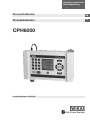
CPH6000
ProzessKalibrator CPH6000
ProcessCalibrator
CPH6000
GB Operating Instructions ProcessCalibrator
Betriebsanleitung ProzessKalibrator
Seite 56 - 110
Information
This symbol provides you with information, notes and tips.
Warning!
This symbol warns you against actions that can cause injury
to people or damage to the instrument.
2
WIKA Operating Instructions ProcessCalibrator
11069023 05/2006 GB/D
D
Page 4 - 55
ProcessCalibrator
CPH6000
Contents
11069023 05/2006 GB/D
1.
1.1
1.2
1.3
2.
3.
3.1
3.2
4.
4.1
4.2
4.3
5.
5.1
5.2
5.3
5.4
5.5
6.
6.1
7.
8.
8.1
8.2
8.3
9.
9.1
9.2
9.3
9.4
10.
10.1
10.2
10.3
10.4
10.5
10.6
10.7
11.
11.1
12.
13.
14.
15.
16.
17.
18.
GB
General
4
5
General safety instructions
7
Safety information for the CPH6000 rechargeable battery
8
General product information
Charging the internal battery
10
Connecting of CPT6000 reference pressure sensor
12
12
Mechanical connections
13
Electrical connections
Electrical connections to the CPH6000 DigitalConsole
14
15
Electr. connections for potential-free contact pressure switches
16
Electrical connections for a 2-wire test item
17
Electrical connections for a 3-wire test item
Basic settings and requirements
18
18
Examples: Test and calibration assembly (with test pumps)
18
Requirements for test assemblies with the CPH6000
20
Important device settings for calibrations using calibration mode
20
Unit and resolution
21
Zero error or offset correction
User interface
22
22
General user instructions for configuration of operating modes
Menu structure (MEASUREMENT/CALIBRATION/
SWITCH TEST)
23
Display description
24
Device status message briefly after switching on the CPH6000 24
25
Display contents for the operating modes
28
Contents of the SETUP-MENUS
Operating modes
30
30
MEASUREMENT mode
32
MEASUREMENT mode with test item
34
CALIBRATION mode
42
PRESSURE-SWITCH TEST mode
SETUP-Additional menu options
44
44
Function
45
CPH-Info
46
Reference Sensor
47
Ref. Sensor List
48
CPH-Settings
49
Interface
49
Clear CalData
Troubleshooting measures
50
50
Table: Fault description and measures
Re-calibrating and servicing
52
Transport of the system
52
Storage of the system
53
Placing out of service
53
Specification
54
Accessories
54
Addresses
111
WIKA Operating Instructions ProcessCalibrator
3
ProcessCalibrator
CPH6000
GB 1. General
In the following chapters detailed information on the ProcessCalibrator CPH6000
and its proper use can be found.
Should you require further information, or should there be problems which are not
dealt within detail in the operating instructions, please contact the address listed
on the last page.
Factory calibration of the instrument is according to relevant international standards.
The warranty period for the CPH6000 ProcessCalibrator is 24 months according to
the general terms of supply of ZVEI.
The guarantee is void if the appliance is put to improper use or if the operating
instructions are not observed or if an attempt is made to open the appliance.
We also point out that the content of these operating instructions neither forms
part of an earlier or existing agreement, assurance or legal relationship nor is meant to change these. All obligations of WIKA Alexander Wiegand GmbH & Co. KG
result from the respective sales contract and the general business terms of WIKA
Alexander Wiegand GmbH & Co. KG.
WIKA is a registered trade mark of WIKA Alexander Wiegand GmbH & Co. KG.
Names of companies or products mentioned in this handbook are registered trade
marks of the manufacturer.
We reserve the right to effect reasonable changes on the basis of technical improvements.
Any reproduction of this manual or parts thereof by any means is prohibited.
Version key regarding firmware and respective manual.
Firmware
31.08.05
34.10.05
© 2005 Copyright WIKA Alexander Wiegand GmbH & Co. KG
4
WIKA Operating Instructions ProcessCalibrator
11069023 05/2006 GB/D
Manual
V 1.1
V 1.2
ProcessCalibrator
CPH6000
1.1 General safety instructions
GB
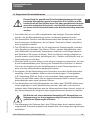
This device has been designed and tested in accordance with the
relevant safety regulations for electronic devices. However, its
trouble-free operation and reliability cannot be guaranteed unless
the standard safety measures and special safety advise given in
this manual is followed when using the device.
1. The system must only be operated by trained and authorised personnel who
know the manual and can work according to them.
2. Trouble-free operation and reliability of the device can only be guaranteed so
long as the device is not subjected to any climatic conditions other than those
stated under “Specification“.
3. The CPH6000 always has to be handled with the care required for an electronic
precision instrument (protect from humidity, impacts, strong magnetic fields,
static electricity and extreme temperatures, do not insert any objects into the
instrument and its openings). The device and sensors must be handled with
care (don‘t throw, hit, etc.). Protect plugs and sockets from contamination.
4. If the device is moved from a cold to a warm environment, condensation may
cause the equipment to fail. You should therefore ensure the device temperature
has adjusted to the ambient temperature before trying to switch it on.
5. If the instrument is to be connected to other devices (e.g. via serial interface)
care must be taken when designing the equipment connections. It is possible
that internal wiring within the external device (e.g. connection of GND to Earth)
may cause excessive voltages which could harm or destroy the instrument or
other connected devices.
6. The mains plug of the battery charger unit powering the CPH6000 must always
be accessible when connected to a power outlet, i.e., you must be able to pull
the plug from the power outlet without difficulty, at any time. However if
possible, for safety reasons, it should be operated without the battery charger
attached.
11069023 05/2006 GB/D
If the device is operated with a faulty mains power supply (e.g.
short circuit from mains voltage to output voltage) this could
result in dangerous voltages at the device (e.g. at the sensor
socket or serial interface).
7. Significant electromagnetic radiation can adversely affect the measuring signal
of the reference sensor (and therefore also the test item) or even disrupt the
display of the signal completely.
WIKA Operating Instructions ProcessCalibrator
5
ProcessCalibrator
CPH6000
GB 8. The display window is made of glass (which can splinter). Unless there is no
possibility of this glass breaking during operation, anyone in the close vicinity of
the equipment, must wear eye protectors, both before and during operation.
9. Test and calibration assemblies must always be constructed and also dismantled in an unpressurised state (atmosphere).
10. If the CPH6000-Pressure Sensor is used for applications with oil as the fluid
media, then subsequent use with fuels or gases is prohibited, since this could
cause an explosion and risks harm to both people and machinery.
11. If the equipment is damaged and might no longer operate safely, then it should
be taken out of use and securely marked in such a way so that isn‘t used
again.
Operator safety may be at risk if:
There is visible damage to the device
The device is not working as specified
The device has been stored under unsuitable conditions for an extended
period of time.
If there is any doubt, please return the device to the manufacturer for repair or
maintenance.
11069023 05/2006 GB/D
12. Customers must not attempt to alter or repair the device themselves. Please
return the device to the manufacturer for any repair or maintenance.
13. Any operation not included in the following instructions or outside the
specifications must not be attempted.
6
WIKA Operating Instructions ProcessCalibrator
ProcessCalibrator
CPH6000
1.2 Safety information for the CPH6000 rechargeable battery
GB
The electrolytes within the CPH6000s rechargeable batteries are
inflammable. If there is any visible leakage the equipment must be
kept away from ignition sources and should be wrapped in
absorbent cloths.
If there is any contact with this electrolyte it should be removed
by rinsing thoroughly with clean water.
If it comes into contact with the eyes - Do not rub them
If it comes into contact with the skin - soap should also be used.
Medical assistance should be sought immediately!
11069023 05/2006 GB/D
In the case of fire, the incineration gases are irritating and
poisonous.
If this occurs appropriate action must be taken and immediate
medical assistance sought!
WIKA Operating Instructions ProcessCalibrator
7
ProcessCalibrator
CPH6000
GB 1.3 General product information
Application
The CPH6000 Process Calibrator unites the advantages of a compact,
handheld instrument with the extensive functionality of a laboratory calibration
instrument. In this way, everyday tasks in the field become particularly simple
such as measuring, testing or calibrating pressure measuring instruments
(including generating certificates) and also testing pressure switches.
Reference pressure sensors
There are numerous reference pressure sensors for the CPH6000 Process
Calibrator, with an accuracy of 0.025 % and measuring ranges from 250 mbar to
1000 bar to choose from, they can be interchanged on the instrument quickly
and without the need for tools. The pressure sensor employed can also be
mounted remotely using an extension cable. When the CPH6000 is switched on,
the attached reference pressure sensor is recognized automatically, so that no
further configuration is needed.
11069023 05/2006 GB/D
Instrument features:
The instrument has 3 operating modes: MEASURING/CALIBRATION/SWITCH
TEST, which each offer the maximum possible user-convenience in relation to
the application.
In order to power the test specimens and to read their measurement signals,
the instrument has various electrical inputs and outputs, which are all shielded
from harsh field conditions by captive protective covers. In the operating mode
“MEASURING (with test specimen)“ and “CALIBRATION“ the measured values
of both the reference pressure sensor and the test specimen are displayed, as
well as their deviation in both current pressure units and in %. In this way the
operator is immediately informed whether the test specimen meets the accuracy-class or not. The difference between these two modes is that the calibration
data in the “CALIBRATION“ mode are stored internally and can later be transferred onto printable certificates, using software (PrintCal or EASYCal).
The CPH6000 Process Calibrator has both an RS-232 and a USB interface,
selectable via menu, to enable the transfer of this data to a PC.
The instrument is powered by an internal rechargeable Lithium-Ion battery,
which can be recharged using the battery charger supplied.
8
WIKA Operating Instructions ProcessCalibrator
ProcessCalibrator
CPH6000
11069023 05/2006 GB/D
SETUP menu
The SETUP menu, accessed using the SETUP key, allows you to select and
configure the desired operating mode (MEASURING/CALIBRATION/SWITCH
TEST), to recall a stored function or to change general instrument settings e.g.:
the menu language.
WIKA Operating Instructions ProcessCalibrator
9
GB
ProcessCalibrator
CPH6000
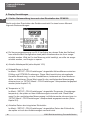
GB 2. Charging the internal battery
The mains plug of the battery charger unit powering the CPH6000 must always
be accessible when connected to a power outlet, i.e., you must be able to pull the
plug from the power outlet without difficulty, at any time. However if possible, for
safety reasons, it should be operated without the battery charger attached.
Use with a defective power supply unit (e.g. short-circuit from
mains voltage to the output voltage) can produce lethal voltages
within the equipment!
The equipment is delivered with the batteries 25 % - 50 %charged and they should
first be fully charged before initial operation. The battery level status (charge in %)
is briefly indicated as the equipment is turned on, and/or it can be viewed via the
“SETUP-Additional Menu Options, CPH-Settings“ (see chapter 10.5) during operation.
The temperature during charging must be between 10 °C and 45 °C.
When the mains lead/battery charger is connected to the CPH6000,
the rechargeable battery will be charged, even if the CPH6000 is
turned off.
The battery level during storage or shipping should be between
30 % - 50 %.
When the battery charger is not in use, its power supply plug should be disconnected from the mains socket. Do not leave the battery charger attached
to the rechargeable battery longer than one day, since overloading can shorten
its lifespan. If, after 24 hours, the rechargeable battery isn't fully charged, you
should contact the manufacturer. When unused, a fully charged battery will lose
its charge over time.
10
WIKA Operating Instructions ProcessCalibrator
11069023 05/2006 GB/D
Only use the battery charger approved by the manufacturer.
ProcessCalibrator
CPH6000
Extreme temperatures have an adverse effect on battery charging. As a result,
the battery may first need to be either cooled or warmed, as appropriate.
When the battery is nearly empty, the message "low BAT" appears in the lower
info display. With 0 % battery level, the equipment automatically switches itself
off and must then be recharged using the battery charger.
Do not use a damaged or worn battery charger.
Keep the equipment between 15 °C and 35 °C.
Equipment with either a warm or a cold battery might not operate fully.
11069023 05/2006 GB/D
In particular, Li-Ion rechargeable batteries operate poorly under 0 °C.
WIKA Operating Instructions ProcessCalibrator
11
GB
ProcessCalibrator
CPH6000
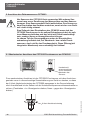
GB 3. Connection of CPT6000 reference pressure sensors
Only use CPT6000 Series sensors! Using other sensors can
damage both the CPH6000 and the sensors. Switch the
instrument off before changing sensors. Unless the sensor is
properly connected before the equipment is switched on, it may
not be correctly identified by the instrument.
When the CPH6000 is switched on, the CPT6000 must be
mounted in the position in which the measurements will be made
and must not be subjected to any pressure, but rather should be
at atmospheric pressure. For Gauge-Pressure sensors, there is a
pressure-equalising vent in the top of the sensor under the plastic
fitting. This vent (with integrated membrane) must remain
absolutely clear!
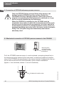
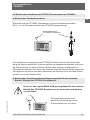
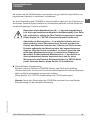
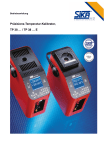
3.1 Mechanical connection of CPT6000 pressure sensors to the CPH6000
Manual quickconnectin enabling easy changeof sensors
6-sided anti-rotation stop
12
WIKA Operating Instructions ProcessCalibrator
11069023 05/2006 GB/D
To fit the CPT6000 pressure sensor, it must be placed, connecting thread first, in
the hexagonal sensor bracket of the instrument, so that the 6-sided anti-rotation
stop of the CPT6000 sits accordingly in the sensor bracket. Subsequently, the sensor can be secured with the hand-operated, quick-connect mechanism.
(tighten = turn clockwise; release = turn anti-clockwise)
ProcessCalibrator
CPH6000
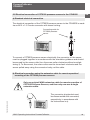
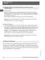
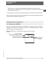
3.2 Electrical connection of CPT6000 pressure sensors to the CPH6000
GB
a) Standard electrical connection
The electrical connection of the CPT6000 pressure sensor to the CPH6000 is made
via an M12 x 1.5 Circular connector with screw-locking.
Connecting cable for
CPT6000 pressure
sensor
To connect a CPT6000 pressure sensor electrically, the connector on the sensor
must be plugged together in accordance with the orientation guidance and should
be secured by the screw collar (turn the screw collar clockwise without overtightening it). To disconnect, the screw collar must be turned anti-clockwise and the
sensor pulled away using the connector body, not the cable.
b) Electrical connection using the extension cable for remote operation/
mounting of the CPT6000 pressure sensors
Only use original WIKA extension cable for remote operation of
CPT6000 Pressure Sensors, and then only ever use a single
extension cable.
11069023 05/2006 GB/D
The connector plug/socket must
be disconnected and connected,
respectively, in accordance with
the instructions in a).
WIKA Operating Instructions ProcessCalibrator
13
ProcessCalibrator
CPH6000
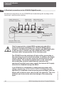
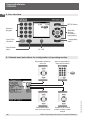
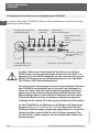
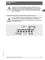
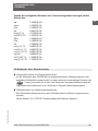
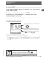
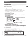
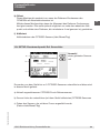
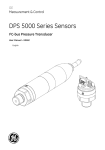
GB 4. Electrical connections to the CPH6000 DigitalConsole
All electrical connections for the CPH6000 are located along the top edge of the
instrument (see the picture below).
Supply Voltage 24 V*
(activated trough Menu)
Measurement
Input* Voltage
Measurement input*
current or Switch Test
Mains Input/Charger
socket (Battery is charged
automatically)
Interface Port; USB
or RS-232 (selected
through Menu)
Connector cable for the
CPT6000 pressure sensor
* Connectors: 4 mm test sockets
Only the appropriate, original WIKA components should be
connected to these electrical ports. (Only the WIKA battery
charger to the Mains Input/Charger socket, only WIKA test cable
to the laboratory sockets and only a WIKA RS-232 or USB
interface cable, as appropriate, to the interface port).
If the CPH6000 is configured for reading test specimens with
voltage outputs (e.g.: 0-1 V / 0-2 V / 0-5 V / 0-10 V) and no test
specimen is connected to the measuring input (voltage), then the
display will not show a zero value for the test specimen. This is intentional, and is due to the electrical design of the measuring
input.
14
WIKA Operating Instructions ProcessCalibrator
11069023 05/2006 GB/D
The CPH6000 must be switched off before either connecting or
disconnecting any of the electrical cables. In addition, the supply
voltage marked on the power supply unit must match the local
mains voltage. The measuring inputs must not be overloaded
electrically (see technical specifications) and when test
specimens have their own power supply, the internal 24 V supply
must also be disabled through the Menu.
ProcessCalibrator
CPH6000
The internal 24 V power supply must not be short-circuited and
nor should the maximum output current through the circuit
exceed 50 mA. (In addition, the current should not drop below
20 mA in order to ensure accurate current measurement)
GB
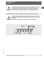
4.1 Electrical connections for potential-free contact pressure switches
Only potential-free (passive) switches, as shown in the drawing
and using the supplied test cable, should be connected to the
CPH6000.
A current or voltage input could damage the CPH6000.
11069023 05/2006 GB/D
potential-free
Switch
WIKA Operating Instructions ProcessCalibrator
15
ProcessCalibrator
CPH6000
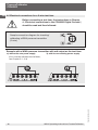
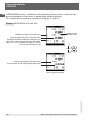
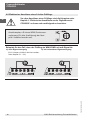
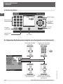
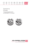
GB 4.2 Electrical connections for a 2-wire test item
Before connecting a test item, the instructions in Chapter
4, “Electrical connections to the CPH6000 Digital Console“,
should be read and then followed.
Sample connection diagram for checking/
calibrating a WIKA pressure transmitter
(2-wire).
Example with a WIKA pressure transmitter with mA output as the test item:
b) with its own existing power supply
11069023 05/2006 GB/D
a) without its own power supply
(24 V must be activated via the Menu;
see Chapter 9.1 - 9.4)
16
WIKA Operating Instructions ProcessCalibrator
ProcessCalibrator
CPH6000
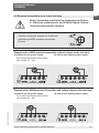
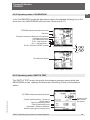
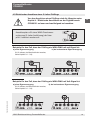
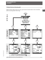
4.3 Electrical connections for a 3-wire test item
GB
Before connecting a test item, the instructions in Chapter
4, “Electrical connections to the CPH6000 Digital Console“,
should be read and then followed.
Sample connection diagram for checking/
calibrating a WIKA pressure transmitter
(3-wire).
Example with a WIKA pressure transmitter with mA output as the test item:
a) without its own power supply
(24 V must be activated via the Menu;
see Chapter 9.1 - 9.4)
b) with its own existing power supply
Example with a WIKA pressure transmitter with voltage output as the test item:
b) with its own existing power supply
11069023 05/2006 GB/D
a) without its own power supply
(24 V must be activated via the Menu;
see Chapter 9.1 - 9.4)
WIKA Operating Instructions ProcessCalibrator
17
ProcessCalibrator
CPH6000
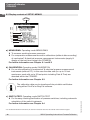
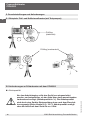
GB 5. Basic settings and requirements
5.1 Example: Test and calibration assembly (with test pump)
mA
Test Item (electrical)
Test Item (mechanical)
5.2 Requirements for test assemblies with the CPH6000
Before starting any task, the CPH6000 should be switched on
briefly to determine that there is sufficient charge in the battery.
(Battery level in %). The battery level is indicated briefly after
powering up in a device-status message (see Chapter 8.1). 100 %
battery charge will allow approximately 8 hours of instrument
operation.
18
WIKA Operating Instructions ProcessCalibrator
11069023 05/2006 GB/D
Battery level
ProcessCalibrator
CPH6000
Initially the test assembly must be mechanically constructed and, if necessary,
electrically connected (both in accordance with the previous Chapters).
GB
Before switching the CPH6000 on, it should be ensured that the test assembly is
not pressurised (System is vented to atmosphere) and that the equipment is correctly assembled (correct mounting position).
In particular, assemblies with small measuring ranges (e.g. < 1 bar)
are orientation dependent (i.e. the mounting position influences
the measured signal considerably). This can be compensated, if
necessary, using the Tare function (see Chapter 10.1 “SETUPAdditional menu options: Functions“).
Absolute-pressure measuring ranges < 1 bar are, by definition, in
an overload condition at atmospheric pressure. Therefore no
measured value appears in the display, but rather 3 dashes,
indicating a pressure outside of the measuring range of the
attached sensor. If the pressure is reduced, so that it falls within
the permissible measuring range, then the measured value
appears in the display. Since absolute pressure measuring ranges
< 1 bar are always “overloaded“ at atmospheric pressure, for
these measuring ranges the “Overload“ time limit function is
deactivated in the “SETUP“ menu option: Reference Sensor“ (see
Chapter 10.3).
Compensation for height differences
If a significant elevation difference exists between the Reference Sensor
(CPH6000) and the test specimen, then the pressure difference, based on the
head pressure, can be compensated automatically via the menu.
(See Chapter 10.5 “SETUP-Additional menu options: CPH-Settings“).
11069023 05/2006 GB/D
Note: After switching on the CPH6000, a brief device status message
appears showing the current settings.
WIKA Operating Instructions ProcessCalibrator
19
ProcessCalibrator
CPH6000
GB 5.3 Important device settings for calibrations using calibration mode
Calibration date
The instrument has an integral real-time clock with date. The current date of a
calibration is stated later in the calibration certificate. Before starting a
calibration you must ensure that the internal date of the CPH6000 is correct
(see Chapter 10.5 “SETUP-Additional menu options: CPH-Settings“).
Note: After switching on the CPH6000, a brief device status message
appears showing the current settings.
Calibration temperature
On calibration certificates for pressure measuring instruments, the ambient
temperature during the calibration is also always stated along with the calibration data. Therefore, the current ambient temperature can be entered into the
CPH6000 via its menu so that it can later be included on the calibration certificate. Before starting a calibration you must ensure that the temperature value
set in the CPH6000 corresponds to the ambient temperature (see Chapter
10.5 “SETUP-Additional menu options: CPH-Settings“).
Note: After switching on the CPH6000, a brief device status message
appears showing the current settings.
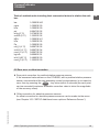
5.4 Unit and resolution
11069023 05/2006 GB/D
After selecting one of the Main Menu Items (e.g.: MEASURING, CALIBRATION
or SWITCH TEST) from the “SETUP“ menu (press “SETUP“ key), using the menu
Option: “Unit“, and its associated submenu respectively (move the cursor to “Unit“
and press the right or left arrow), you can select the unit and adjust its resolution
(see Chapter 9: “Operating modes“).
20
WIKA Operating Instructions ProcessCalibrator
ProcessCalibrator
CPH6000
Table of available units including their conversion factors in relation the unit:
bar:
bar
mbar
hPa
psi
inHg (0 °C)
cmHG (0 °C)
MPa
kPa
Pa
mH2O (4 °C)
cmH2O (4 °C)
mmH2O (4 °C)
kg/cm2
inH2O (60 °C)
mmH2O (0 °C)
1.00000E+00
1.00000E-03
1.00000E-03
6.89475E-02
3.37690E-02
1.33322E-02
1.00000E+01
1.00000E-02
1.00000E-05
9.80670E-02
9.80670E-04
9.80670E-05
9.80665E-01
2.48800E-03
1.33322E-03
5.5 Zero error or offset correction
Zero point correction for positive/relative pressure sensors
If the measured value shown on the CPH6000, with a positive/relative pressure
sensor connected and the test assembly vented to atmosphere, is not equal to
zero, then by pressing the CLEAR - key twice (within 5 seconds) the zero point
can be corrected (maximum allowable correction value is twice the magnitude
of the accuracy class).
11069023 05/2006 GB/D
Offset correction for absolute pressure sensors
An offset correction for absolute pressure sensors can be made via the menu
(see Chapter 10.3 “SETUP-Additional menu options: Reference Sensor“).
WIKA Operating Instructions ProcessCalibrator
21
GB
ProcessCalibrator
CPH6000
GB 6. User interface
SETUP-Menu
Numeric
Keypad
Selection
& Input
Activation
(navigation)
Input Confirmation
1 stage/step
back
Clear/Delete
Input
On / Off
6.1 General user instructions for configuration of operating modes:
Parameter selection
from list
Input of parameter +
input confirmation
+
ENTER
Parameter selection from sub-menu
22
Selection of current
cursor position within
menus
WIKA Operating Instructions ProcessCalibrator
11069023 05/2006 GB/D
}
ProcessCalibrator
CPH6000
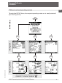
7. Menu structure (operating modes)
GB
Through the SETUP-Menu, the required operating mode can be easily selected
(see drawing below) .
SETUP-Menu
SETUP
SELECT
SELECT
SELECT
SELECT
Configuration
SELECT
Operating
Arbeitsmodi
Modes
11069023 05/2006 GB/D
SELECT
opt.
Changing the test item display is possible
(Pressure <--> electrical signal) via
WIKA Operating Instructions ProcessCalibrator
23
ProcessCalibrator
CPH6000
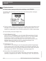
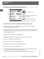
GB 8. Display description
8.1 Device status message briefly after switching on the CPH6000
Immediately after switching on the instrument, the following status messages
appear briefly:
a->
b->
c->
d->
e->
f->
a) The 24 V supply voltage (accessed from the top edge of the instrument) can be
switched on or off during the configuration of each operating mode. If it is not
needed for a measurement, then it should be switched off, in order to save energy.
b) Current battery level (see Chapter 10.5)
c) Height difference in [mm]
In the “SETUP \ CPH-Settings“ menu the height difference between the test
specimen and the CPT6000 pressure sensor can be set. This value prompts
an automatic correction calculation based on a head pressure, which
compensates for the pressure difference. This value must be correct for the
following measuring procedure and/or be altered accordingly in the
“SETUP \ CPH-Settings“ menu (see chapter 5.2).
e) Current date of the integrated real-time clock
The date in the real-time clock, which is also later noted within the calibration
certificate, is adjusted via the “SETUP \ CPH-Settings“ menu. This value must
24
WIKA Operating Instructions ProcessCalibrator
11069023 05/2006 GB/D
d) Temperature in [°C]
In the “SETUP \ CPH-Settings“ menu the temperature (ambient temperature)
can be entered, which is also later recorded on the calibration certificate. This
value must be correct for the following measuring procedure and/or be altered
accordingly in the “SETUP \ CPH-Settings“ menu (see chapter 5.2)
ProcessCalibrator
CPH6000
be correct for the ensuing measuring procedure and/or be altered accordingly in GB
the “SETUP \ CPH-Settings“ menu (see chapter 5.2).
f) Calibration date for the electrical measurement inputs to the CPH6000
(Year/Month/Day)
After the status message the display reverts to the screen for the operating mode
used last (see following chapter 8.2).
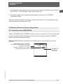
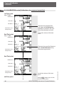
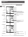
8.2 Display contents for the operating modes
8.2.1 Operating mode: MEASURING
When a CPH6000 with a CPT6000 pressure sensor connected to it is first switched
on, the instrument (after displaying a brief status message) switches to MEASURING mode (see following picture).
Display: MEASURING with Reference pressure sensor only (without test item)
Measuring range of CPT6000
reference-pressure sensor (the one
currently connected)
pressure unit
(can be set
via menu)
11069023 05/2006 GB/D
Current measured-value of the
reference pressure sensor
WIKA Operating Instructions ProcessCalibrator
25
ProcessCalibrator
CPH6000
GB In MEASURING mode, in addition to the reference-pressure value, a test item can
also be displayed on the screen in parallel (see following picture).
For configuration instructions, please see Chapter 9.1 and 9.2
Display: MEASURING with test item
pressure unit
(of test item)
Measuring range of the test item
Current measured-value of the test item
Deviation/Difference between reference and
test item in the selected pressure Units and,
either, in % of the measuring range (% FS) or
% of measured-value (% rd)
Pressure signal (test item)
P
switchable
I/U
Output signal (type) of the test item
Current value of the output signal (test item)
11069023 05/2006 GB/D
Electr. signal (test item)
26
WIKA Operating Instructions ProcessCalibrator
ProcessCalibrator
CPH6000
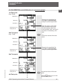
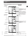
8.2.2 Operating mode: CALIBRATION
GB
In the CALIBRATION mode the data shown above the (dashed dividing) line is the
same as in the “MEASURING with test item“ Mode (see 8.2.1).
CPT6000 reference pressure sensor
Test item
Deviation between reference and test item
Calibration set-point
True calibration value
P-01: test item No. 1
}
<01>: test point No. 1
ID-No: test item IDENT number
{
{
P
Pressure signal (test item)
switchable
I/U
True test item signal
Electr. signal: test item
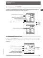
8.2.3 Operating mode: SWITCH TEST
The SWITCH TEST mode, along with the reference pressure sensor data (see
MEASURING mode), displays the Status and Switching Points of the pressure
switch.
11069023 05/2006 GB/D
CPT6000 reference pressure sensor
Current switch position / pressure
switch status
Opening switching point
Closing switching point
Hysteresis / distance between
Switch opening and closing point
WIKA Operating Instructions ProcessCalibrator
{
pressure unit
(can be set
via menu)
27
ProcessCalibrator
CPH6000
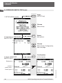
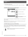
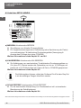
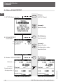
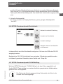
GB 8.3 Display contents of SETUP-MENUS
SETUP
a ->
b ->
c ->
d ->
e ->
f ->
g->
h->
i->
j->
a) MEASURING: Operating mode MEASURING
To measure working/process pressures
For comparative measurements and/or calibrations (without data recording)
of mechanical* & electrical pressure measurement instruments (supply &
display of the test item through the CPH6000)
For further information see Chapter 9.1 and 9.2
b) CALIBRATION: Operating mode CALIBRATION
For on-site calibration of mechanical* & electrical pressure measurement
instruments (without PC). In this case the data sets (for up to 16 test
specimens, each with up to 32 test points including Date & Time) are
recorded within the CPH6000.
For further information see Chapter 9.3
c) SWITCH TEST: Operating mode SWITCH TEST
For the easy checking/verification of pressure switches, including automatic
calculation of the switch hysteresis.
For further information see Chapter 9.4
* For mechanical indication instruments, the test item measured value must be entered via the Numeric Keypad.
28
WIKA Operating Instructions ProcessCalibrator
11069023 05/2006 GB/D
The calibration data can be transferred into printable certificates
using either PrintCal or EasyCal software.
ProcessCalibrator
CPH6000
d) Functions: Operating functions such as:
Tare: Offset correction for reference pressure sensors
Min/Max: Minimum/Maximum memory
Alarm: Min/Max alarm (visual & audible)
Filter: Smoothing the signal of the reference sensor
For further information see Chapter 10.1
GB
e) CPH-Info: General CPH6000 instrument data such as:
Calibration data for the electrical measurement inputs
Firmware number
Serial-No. of the device
For further information see Chapter 10.2
f) Reference Sensor: Data for the currently connected reference pressure
sensor such as:
Measurement range
Accuracy class
Sensor measurement type
Information in the event of reference sensor overpressure
Calibration data for the reference sensor
For further information see Chapter 10.3
g) Reference Sensor list:
List of the stored reference sensors that can be attached and calibrated.
For further information see Chapter 10.4
11069023 05/2006 GB/D
h) CPH Settings:
Info: on battery level
Display options of: Menu language, system time / system clock, displaybrightness, powersave function (automatic energy saving mode; see
Chapter 10.5)
Entry/Input options:
- ambient temperature during the calibration (see Chapter 5.2)
- height difference between reference and pressure sensor
(see Chapter 5.2).
For further information see Chapter 10.5
i) Digital Interface:
Switch between USB and RS-232 digital interfaces incl. baud rate entry
For further information see Chapter 10.6
j) Clear CalData:
All stored calibration data will be deleted (Clear complete storage space)
For further information see Chapter 10.7
WIKA Operating Instructions ProcessCalibrator
29
ProcessCalibrator
CPH6000
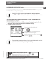
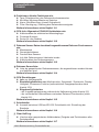
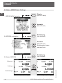
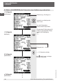
GB 9. Operating modes
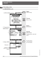
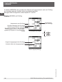
9.1 MEASURING mode
1. SETUP-MENU access
SETUP
Press
(SETUP-key)
Choose
(Menu-item)
2. Preparation for
MEASURING
SELECT
a
b
c
d, e
f
g
h
i
3. Mode: MEASURING
Select
(the option)
Choose
(Menu-item);
Configuration, see next
page
SELECT
Confirmation
(of the inputs)
Reference ->
30
11069023 05/2006 GB/D
pressure unit
(can be set via
menu)
WIKA Operating Instructions ProcessCalibrator
ProcessCalibrator
CPH6000
9.1 MEASURING mode
GB
In order to switch the instrument into “MEASURING“ mode, follow the instructions
on the previous page.
The following is a more detailed explanation of Point: “2. Preparation for
MEASURING“
a: Test item type and respective test item measurement signal: [----] for measurement without test specimen
b: Lower limit of test item measuring range
c: Upper limit of test item measuring range
d: Measurement accuracy of the test item in % FS (with respect to the span) or
% rd (with respect to the measured value)
e: Measurement accuracy of the test item in %
f: Units & resolution (Sub-menu)
Choose & select (standard units)
via
SELECT
Customer-specific units; with respect to
bar (Input via Numeric Keypad)
Display resolution in operating mode via
(back with BACK
)
Short info
11069023 05/2006 GB/D
g: Measurement type for the test item (relative or absolute)
h: Test medium (pneumatic -> gas & hydraulic -> oil)
i: Power supply for test item (on/off) [If no external supply is required for the
test item, “OFF“ should be selected to conserve energy]
xxx
0.00
ENTER
Current coursor position; alter via
} Parameter-selection from list or menu via
Parameter input using numeric keypad
CLEAR
Input confirmation
Clear input
WIKA Operating Instructions ProcessCalibrator
31
ProcessCalibrator
CPH6000
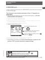
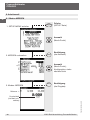
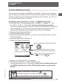
GB 9.2 MEASURING mode (with test item)
SETUP
1. SETUP-MENU access
Press
(SETUP-key)
Choose
(Menu-item)
SELECT
2. Preparation for
MEASURING
a
b
c
d, e
f
g
h
i
Select
(the option)
Choose
(Menu-item);
Configuration, see next
page
SELECT
3. Mode: MEASURING
Confirmation
(of the inputs)
Reference ->
P
Deviation ->
Pressure signal (test item)
32
I/U
switchable
Electr. signal (test item)
WIKA Operating Instructions ProcessCalibrator
11069023 05/2006 GB/D
Test Item ->
ProcessCalibrator
CPH6000
9.2 MEASURING mode (with test item)
GB
To switch the instrument into “MEASURING“ mode (with test item display the test
signal as an electrical signal or as a pressure), in order to carry out a comparative measurement / Calibration without measured-value recording, then follow the
instructions on the previous page.
The following is a more detailed explanation of Point: “2. Preparation for
MEASUREMENT“
a: Test item and respective test item signal [0 ... 20 mA / 4 ... 20 mA / 0 ... 1 V /
0 ... 2 V / 0 ... 5 V / 0 ... 10 V / or mechanical for pressure gauges]
If a comparative measurement with a mechanical gauge (test item) is being
made, then the gauge‘s measured value should be entered via the numeric
keypad and confirmed with ENTER.
b: Lower limit of test item measuring range
c: Upper limit of test item measuring range
d: Measurement accuracy of the test item in % FS (with respect to the span) or
% rd (with respect to the measured value)
e: Measurement accuracy of the test item in %
f: Units & resolution (Sub-menu)
Choose & select (standard units)
via
SELECT
Customer-specific units; with respect to
bar (Input via numeric keypad)
Display resolution in operating mode via
(back with BACK
)
Short info
11069023 05/2006 GB/D
g: Measurement type for the test item (relative or absolute)
h: Test medium (pneumatic -> gas & hydraulic -> oil)
i: Power supply for test item (on/off) [If no external supply is required for the
test item, “OFF“ should be selected to conserve energy]
xxx
0.00
ENTER
Current coursor position; alter via
} Parameter-selection from list or menu via
Parameter input using numeric keypad
CLEAR
Input confirmation
Clear input
WIKA Operating Instructions ProcessCalibrator
33
ProcessCalibrator
CPH6000
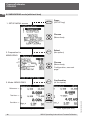
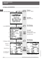
GB 9.3 CALIBRATION mode
SETUP
1. SETUP-MENU access
Press
(SETUP-key)
Choose
(Menu-item)
SELECT
2. Preparation
CALIBRATION
a
b
c
d
e
f
g, h
i
j
k
l
m
n, o
p
Select
(the option)
Choose
(Menu-item);
Configuration, see next
page
SELECT
3. Mode: CALIBRATION
Confirmation
(of the inputs)
Reference ->
Test item ->
P
Pressure signal (test item)
34
I/U
switchable
Test item No. & ->
Test point No.
Electr. signal (test item)
WIKA Operating Instructions ProcessCalibrator
11069023 05/2006 GB/D
Deviation->
ProcessCalibrator
CPH6000
9.3 CALIBRATION mode
GB
In order to put the instrument into “CALIBRATION“ Mode, the procedure on the
previous page should be followed.
The following is a more detailed explanation of Point: “2. Preparation for CALIBRATION“
a: No. of the calibration, and therefore the test item (up to 16 calibrations, each
with up to 32 test points, can be predefined and then recorded).
b: Test Item and respective Test Item signal [0 ... 20 mA / 4 ... 20 mA / 0 ... 1 V /
0 ... 2 V / 0 ... 5 V / 0 ... 10 V / or mechanical for pressure gauges]
c: ID-No. of the test item
d: Measuring point No. of the test item
e: Lower limit of test item measuring range
f: Upper limit of test item measuring range
g:h: Measurement accuracy of the test item in % FS (with respect to the span) or
% rd (with respect to the measured value)
i: Units & resolution (Sub-menu)
Choose & select (standard units)
via
SELECT
Customer-specific units; with respect to
bar (Input via numeric keypad)
Display resolution in operating mode via
(back with BACK
)
Short info
11069023 05/2006 GB/D
j: Measurement type for the test item (relative or absolute)
k: Test medium (pneumatic -> gas & hydraulic -> oil)
l: Power supply for test item (on/off) [If no external supply is required for the
test item, “OFF“ should be selected to conserve energy]
m: No. of test point x
n: Optional “Delay Time“ [sec] to conform with DKD requirements. (see under 9.3)
o: Value of test point x (Input via numeric keypad)
(Test point x+1 and x-1 can be accessed respectively using “
“)
p: True value of the test item (will be recorded during the calibration)
xxx
0.00
ENTER
Current coursor position; alter via
} Parameter-selection from list or menu via
Parameter input using numeric keypad
CLEAR
Input confirmation
Clear input
WIKA Operating Instructions ProcessCalibrator
35
ProcessCalibrator
CPH6000
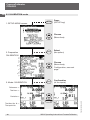
GB 9.3 CALIBRATION mode (preparing the test points of a calibration)
1st Test point
(defining)
Calibration / Test item No. 1
Choice from menu item:
“Set“-value
No. of the test point
Set point ot the test point
1st Test point
(defined)
ENTER
}
Input of the test point (e.g.:
0 bar) via numeric keypad &
confirmation
with
<---
Test point No. 1 = 0 bar
<-- to proceed to 2nd test point
(using returns you to the
previous test point)
11069023 05/2006 GB/D
2nd Test point
(defining)
xth Test Point
(defining)
36
WIKA Operating Instructions ProcessCalibrator
ProcessCalibrator
CPH6000
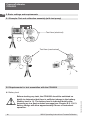
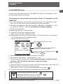
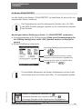
9.3 CALIBRATION mode (preparing the test points of a calibration)
GB
This example clarifies the definition of several test points/pressure steps within a
calibration. It is possible to prepare up to 16 calibrations, each with up to 32 test
points.
Calling up menu items:
Via SETUP & calling up menu item: CALIBRATION (see Chapter 9.3)
Enter the desired/required test points in the way described on the previous page.
Test items with electrical output (4 ... 20 mA, etc.) have to be calibrated according
to the indication of the reference. This means: the pressure has to be set in such
away that the reference value is equal to the set value.
Sometimes it is difficult to adjust the pressure precisely according to the set value,
therefore besides the true value (test item) and set value the current reference value
is also stored.
With the help of the software “PrintCal“ it is then possible to state either true value
(test item) and set value or true value and corresponding reference value in the
calibration certificates.
11069023 05/2006 GB/D
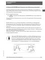
If the calibration is to follow DKD requirements, the measured value for
the following test point should not be recorded before a defined time
has passed (e.g. 30 sec.), consisting of load-change time and steadystate time (see figure A: Calibration Cycle to DKD Directive 6-1 for
measurement uncertainty > 0.6 % of measuring range).
Figure A
WIKA Operating Instructions ProcessCalibrator
37
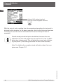
ProcessCalibrator
CPH6000
GB
Optional DKD waiting time [sec]
Input via numeric keypad & confirmation with
ENTER
With the entry of such a waiting time, the acceptance/recording of a test point is
blocked for this duration. (In the above example, after the first test point has been
recorded, 30 seconds must be waited before the second test point can be
recorded.)
Should already stored test points be deleted, because the new
calibration has less test points than the previous one, the “CLEAR“
button has to be pressed. This will delete the current and all following test points. (The erasing procedure will take some seconds.)
11069023 05/2006 GB/D
Note: For deleting the complete stored calibration data all at once
please see Chapter 10.7.
38
WIKA Operating Instructions ProcessCalibrator
ProcessCalibrator
CPH6000
11069023 05/2006 GB/D
GB
WIKA Operating Instructions ProcessCalibrator
39
ProcessCalibrator
CPH6000
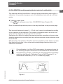
GB 9.3 CALIBRATION mode (Calibration of a pressure transmitter)
1st Test point
(e.g. 0 bar)
Reference ->
Test item ->
Deviation ->
Test item no. & ->
Test point no.
ENTER
2nd Test point
(e.g. 1 bar)
Generate the specified Setpoint acc. to the Reference
(establish a pressure free condition/Atmosphere) and with
<-record the values of this test
point
Reference ->
Test item ->
Deviation ->
Generate the specified Setpoint
acc. to the Reference using
the pressure generator
Test item no. & ->
Test point no.
2nd Test point
Reference ->
Test item ->
Test item no. & ->
Test point no.
ENTER
xth Test point
40
record the values of this test
point
(using BACK returns you to the
previous test point)
WIKA Operating Instructions ProcessCalibrator
11069023 05/2006 GB/D
Deviation ->
ProcessCalibrator
CPH6000
9.3 CALIBRATION mode (Calibration of a pressure gauge)
GB
1st Test point
(e.g. 0 bar)
Reference ->
Generate the specified Setpoint acc. to the test item
using the pressure generator
Test item ->
Deviation ->
If the set value = 0 bar establish a pressure free condition/Atmosphere (test item
must indicate 0 bar; zero-point
correction if necessary) and
with
Test item no. & ->
Test point no.
2nd Test point
(e.g. 1 bar)
ENTER
Reference ->
<--record the values of this test
point
Test item ->
Deviation ->
Generate the specified Setpoint acc. to the test item
using the pressure generator
Test item no. & ->
Test point no.
2nd Test point
Reference ->
Test item ->
11069023 05/2006 GB/D
Deviation ->
Test item no. & ->
Test point no.
ENTER
xth Test point
WIKA Operating Instructions ProcessCalibrator
record the values of this test
point
(using BACK returns you to the
previous test point)
41
ProcessCalibrator
CPH6000
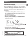
GB 9.4 PRESSURE-SWITCH TEST mode
SETUP
1. SETUP-MENU access
Press
(SETUP-key)
Choose
(Menu-item)
SELECT
2. Preparatin of PRESSURESWITCH TEST
Select
(the option)
a
b
Choose
(Menu-item); Configuration,
see next page
SELECT
3. Mode: PRESSURESWITCH TEST
Confirmation
(of the inputs)
Reference ->
current - >
switch point
Before the Pressure-Switch-test
42
After the Pressure-Switch test
WIKA Operating Instructions ProcessCalibrator
11069023 05/2006 GB/D
Switch point -> {
ProcessCalibrator
CPH6000
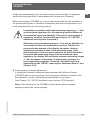
9.4 PRESSURE-SWITCH TEST mode
GB
In order to switch the instrument into “PRESSURE-SWITCH TEST“ mode, follow
the instructions on the previous page.
The SWITCH TEST function is not suitable for electronic switches,
e.g.: PNP- or NPN switches, but is only for mechanical, volt-free switches.
The following is a more detailed explanation of Point: “2. Preparation for
PRESSURE SWITCH TEST“
a: Power supply for test item (on/off) [If no external supply is required for the
test item, “OFF“ should be selected to conserve energy]
b: Units & resolution (Sub-menu)
Choose & select (standard units)
via
SELECT
Customer-specific units; with respect to
bar (Input via numeric keypad)
Display resolution in operating mode via
(back with BACK
)
Short info
11069023 05/2006 GB/D
The calculated measured values of the two switching points and the
hysteresis can be reset by pressing the “0“ key.
xxx
0.00
ENTER
Current coursor position; alter via
} Parameter-selection from list or menu via
Parameter input using numeric keypad
CLEAR
Input confirmation
Clear input
WIKA Operating Instructions ProcessCalibrator
43
ProcessCalibrator
CPH6000
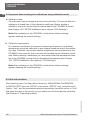
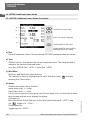
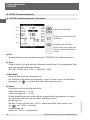
GB 10. SETUP-Additional menu items
10.1 SETUP-Additional menu items: Functions
a -->
Choice from menu item
b -->
c --{
Input via numeric keypad
d -->
e -->
ENTER
Confirmation of the input
(Clear delet the input and the
Min/Max memory is reset)
a) Ref:
Current measured value of the connected CPT6000 pressure reference sensor
b) Tare:
Offset-Function, this adjusts the current measured value. The value entered is
added to the current measured value.
(e.g. Ref. 0.000 & Tara: 1.000 --> [new] Ref. 1.000)
and then
d) Alarm:
Audible and visible Alarm function.
upper alarm limit: > = x bar
lower alarm limit: < = x bar
If the current measured value goes over the set alarm limit, an intermittent alarm
tone sounds and the lower display line blinks.
Activated via:
Move the cursor to the field next to the word alarm that reads “<OFF>“ and
via
toggle it to “<ON>“.
Deactivated via:
Toggle back to “<OFF>“
44
WIKA Operating Instructions ProcessCalibrator
11069023 05/2006 GB/D
c) Min:/Max:
Minimum and Maximum-value memory
The memory is reset by highlighting the value with the cursor
pressing the Clear button.
ProcessCalibrator
CPH6000
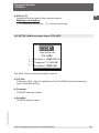
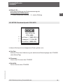
e) Filter [1-5]:
Smoothing of the signal of the reference sensor
Meaning of the figures:
1 = no additional smoothing ... 5 = intense smoothing
GB
10.2 SETUP-Additional menu items: CPH-INFO
a -->
b -->
c -->
This Menu Section lists general data, such as:
a) Cal-Dat:
Calibration Date - date of calibration of the CPH6000 electrical measuring
inputs (Year/Month/Day)
b) Firmware:
CPH6000 firmware version
11069023 05/2006 GB/D
c) SerialNo:
CPH6000 serial number
WIKA Operating Instructions ProcessCalibrator
45
ProcessCalibrator
CPH6000
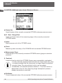
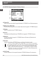
GB 10.3 SETUP-Additional menu items: Reference Sensor
a -->
b --{
c -->
d -->
e -->
f -->
g -->
h -->
i -->
a) Sensor No:
Serial Number of the currently connected CPT6000 reference pressure sensor
b) R - Start / Range-End:
Upper and lower limits of the measuring range of the currently connected
CPT6000 sensor
c) Units:
Basic pressure unit of the CPT6000 sensor
d) Class:
Measuring chain accuracy of the CPH6000 with connected CPT6000 sensor
f) Overload:
Length of time for which the CPT6000-Sensor was unacceptably overloaded.
If in this case the unpressurised instrument no longer reads zero, then
it is highly probable that the instrument no longer meets its specified
accuracy class. The only solution for this is an immediate
recalibration. (For absolute pressure sensors < 1 bar this function is
deactivated, since for this measuring range atmospheric pressure
already represents an overload)
g) Ref Value:
Current measured value of the connected CPT6000 reference pressure sensor
46
WIKA Operating Instructions ProcessCalibrator
11069023 05/2006 GB/D
e) Measurement Type:
Pressure type of the currently connected CPT6000 sensor (gauge or absolute
pressure)
ProcessCalibrator
CPH6000
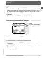
h) Offset:
GB
This menu option only appears if the CPH6000s reference pressure sensor is an
absolute pressure sensor. Through this menu option the measured value of the
reference pressure sensor can be adjusted. This should only be used, however,
as close as possible to the absolute zero, and using a reference that is at least 4
times more accurate than the CPH6000s reference sensor.
i) Calibrated:
Calibration Date of the CPT6000 sensor (Year/Month/Day)
10.4 SETUP-Additional menu items: Ref. Sensor list
a -->
Choice
one of the listed sensors
with
b ->
c ->
The instrument supports up to 5 CPT6000 Sensors and these are listed in this
menu.
a) Currently connected CPT6000 reference pressure sensor
b) Sensor-List of the supported CPT6000-Sensors (calibrated in conjunction with
the instrument)
11069023 05/2006 GB/D
c) Data of the particular sensor, which has been selected using the cursor
(Date: Year/Month/Day)
WIKA Operating Instructions ProcessCalibrator
47
ProcessCalibrator
CPH6000
GB 10.5 SETUP-Additional menu items: CPH-Settings
a -->
b -->
Choice from menu item
c -->
d -->
e -->
Input via numeric keypad
f -->
g -->
h -->
i -->
ENTER
Confirmation of the input
(Clear delet the input and the
memory is reset)
This Menu section lists general instrument settings, such as:
a) Input for ambient temperature, that is later recorded on the calibration
certificate.
b) Input for height difference between Reference-Pressure sensor and test item
used in the automatic correction (deduction of a head pressure)
c) Selection of the menu language (German/English)
Note: Changing the language takes approx. 3 seconds.
d) System Clock Date (Year/Month/Day)
e) System Clock Time (Hour/Minute/Second)
f) Brightness of the display backlight
h) Powersave-Function (automatic switch-off delay for backlight and internal 24 V
test item power supply). If the instrument is idle for the set switch-off delay
period (no keys pressed and no digital communication), then the backlight and
the 24 V test item power supply will be switched off, until any key is pressed
(except ON/OFF) or the instrument is addressed over the digital interface.
48
WIKA Operating Instructions ProcessCalibrator
11069023 05/2006 GB/D
g) Display Contrast (not adjustable)
ProcessCalibrator
CPH6000
i) Current battery charge level
At 10 % the low battery charge warning “low BAT“ is shown in the display.
GB
10.6 SETUP-Additional menu items: Digital Interface
Marks the current configuration
Choice of the interface
SELECT
Confirmation of the choice
Alternation between type of interface and baud rate
This menu allows the configuration of the digital interface. It can be configured for
USB or RS-232.
Regarding the RS-232 interface there is a choice of 3 different baud rates with 8
fixed data bits used, no parity and 1 stop bit.
10.7 SETUP-Additional menu items: CLEAR CalData
If the menu item “CLEAR CalData“ is selected using the cursor and the SELECTbutton is pressed 2 times, all calibration data which is stored in the instrument will
be deleted all at once.
11069023 05/2006 GB/D
Note: The state of the erasing procedure (some seconds) will be
shown in the lower info line.
WIKA Operating Instructions ProcessCalibrator
49
ProcessCalibrator
CPH6000
GB 11. Troubleshooting measures
If faults cannot be repaired, the system must be put out of
operation immediatley and this information is to be given to the
manufacturer.
Repairs must only be carried out by the manufacturer.
Internventions and changes on the appliance are not allowed.
In case of faults caused by defects of the electrical or pneumatic/hydraulic equipment the operators must inform their superiors immediately and call in the qualified
and authorised technical staff for maintenance.
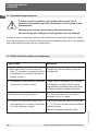
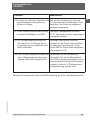
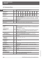
11.1 Table: Fault description and measures
Type of fault
Measures
I. When switching the instrument on,
after 10 seconds no measured value
is displayed, but instead, the whole
display is dark.
Charge the internal battery using the
charger unit.
II. The display is dark and the measures Check that the charger unit is connecunder point I have no effect.
ted properly, and also check (using
appropriately qualified personnel) that
the power supply voltage is correct.
III. Malfunction during operation
Turn the instrument off, and after 5
seconds, turn it on again.
11069023 05/2006 GB/D
The current pressure value is minimally
IV. There is an intermittent alarm tone
and appears in the lower information (2 - 10 %) over or below the permissible
pressure range.
line the message; “range“.
Adjust the pressure appropriately.
50
WIKA Operating Instructions ProcessCalibrator
ProcessCalibrator
CPH6000
GB
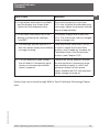
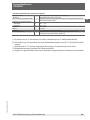
Type of fault
Measures
V. A intermittent audio alarm is audible
and the display only shows lines
rather than the measured value.
The current pressure is more than
10 % over or below the allowable pressure range. Adjust the pressure immediately and appropriately.
VI. In the lower information line of the
display is showing the message
“low BAT“.
The battery charge level is less than
10 %. The instrument must be charged
using its charger unit.
Press any button (other than ON/OFF)
VII. The backlight and the internal 24 V
test-item power supply are suddenly in order to cancel the Power-Save
no longer working.
function, and if needs be, increase the
Countdown-time of the Power-save
function. (see Chapter 10.5)
VIII. The test specimen (read through
the mA and/or V-measuring input)
shows an incorrect value and/or
doesn‘t respond.
Examine the wiring; examine whether
the test specimen‘s measuring range
was entered correctly or, with a test
specimen without its own power
supply, whether the 24 V test specimen
supply voltage is turned on.
11069023 05/2006 GB/D
Further help can be found through WIKA‘s Test & Calibration Technology Department
WIKA Operating Instructions ProcessCalibrator
51
ProcessCalibrator
CPH6000
GB 12. Re-calibrating and servicing
We recommend having the system re-calibrated by the manufacturer at regular
intervals of approx. 12 months. Every re-calibration at the factory also includes a
comprehensive and free checking of all system parameters.
Maintenance advice
Both the CPH6200 and sensors are manufactured using solid-state technology,
and contain no moving parts which could wear. If the instrument housing has
been opened, the warranty becomes invalid.
To clean the membrane keyboard and the display, use only customary plastic or
glass cleaning agents in compliance with the guidelines of the manufacturer. Use
clothes which are not prone to generate fluffs.
Before cleaning the surface of the instrument, it has to sure that it
is not pressurized, the power switched off and the power supply
disconnected.
The electrical connections along the upper edge of the
instruments should not come into contact with a damp cloth.
13. Transport of the system
Before the system is shipped all remains of any medium stuck to
it must be removed. This is particularly important if the medium is
a health hazard such as a corrosive, toxic, carcinogenic,
radioactive, etc.
Please follow the following instructions to prevent damage.
1. Wrap the system in antistatic plastic foil.
2. Using the insulating material, place the system in the box in such a way that
there is about the same amount of insulating material on all sides of the
transport box.
3. If possible add a bag of desiccant to the box
52
WIKA Operating Instructions ProcessCalibrator
11069023 05/2006 GB/D
Before returning any equipment, please fill out the appropriate Goods-Return
Form, found on the WIKA Web site (www.wika.de see: Service/Product return),
and a reference number will be issued to you. Then send the instrument with this
reference number attached to the delivery address indicated.
ProcessCalibrator
CPH6000
4. Make sure that the shipment is marked as transport of a highly sensitive
measuring instrument.
GB
14. Storage of the system
Before the system is stored all remains of any medium stuck to it
must be removed. This is particularly important if the medium is a
health hazard such as a corrosive, toxic, carcinogenic,
radioactive, etc.
The storage place must satisfy the following conditions:
Ambient temperature: 0 to 70 °C (Temperatures above 40 °C can affect the
capacity of the rechargeable battery)
Humidity: 35 to 85 % relative humidity without condensation
Avoid the following influences:
Direct sunlight or vicinity to hot objects
Mechanical vibration
Soot, steam, dust and corrosive gasses
Explosion-hazard environment, inflammable atmosphere
Please follow the following instructions to avoid damage.
1. Wrap the system in antistatic plastic foil.
2. Using the insulating material, place the system in the box in such a way that
there is about the same amount of insulating material on all sides of the
transport box.
3. If the system is stored for a longer time (more than 30 days) add a bag with
desiccant to the box.
15. Placing out of service
11069023 05/2006 GB/D
Before the system is shipped all remains of any medium stuck to
it must be removed. This is particularly important if the medium is
a health hazard such as a corrosive, toxic, carcinogenic,
radioactive, etc.
When disposing of the system please observe the legal and local
regulations in force. For the final disposal of the system a special firm
qualified for this is to be commissioned.
WIKA Operating Instructions ProcessCalibrator
53
ProcessCalibrator
CPH6000
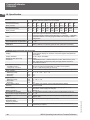
GB 16. Specification
Pressure range
Over pressure safety
Burst pressure
Pressure range
Over pressure safety
Burst pressure
Type of pressure
bar
bar
bar
bar
bar
bar
Units
Accuracy (measurement chain)
Active temperature compensation °C
Permissible ambient temperature °C
Calibration
1 integral pressure transmitter (interchangeable without tools) 1;
optional: external operation via 1.2 m cable
0.25
0.4
0.6
1
1.6
2.5
4
6
10
16
1.6
2
4
5
10
10
17
35
35
80
2.4
2.4
4.8
6
12
12
20.5 40
42
96
25
40
60
100
160
250
400
600 1000
80
80
120
200
320
500
800 1200 1500
96
96
550
800 1000 1200 1700 2400 3000
{In addition to the above-specified gauge pressures; Vacuum,
compound range and absolute pressures are available};
{Compound ranges: minimum span 400 mbar, e.g. -200 mbar ... +200 mbar}
15 standard units & one freely-programmable unit; see page 4 Menu
configuration
0.025 % FS*
0 ... 50
0 ... 50
Factory calibration certificate (optional: DKD calibration certificate)
CPH6000 Digital Instrument specific details:
Calibration mode
MEASURING / CALIBRATION / SWITCH TEST
Display
Large graphic display for reference & test item signals and additional
information
Display definition
Up to 6 digits; selectable
Measuring rate (pressure):
Values 2/sec
Functions
CALIBRATION-Func., SWITCHTEST-Func. Min-, Max-memory, Tare,
Min-, Max-alarm (visual), filter (rolling average). Offset-correction,
PowerSave-Function
CALIBRATION function:
- Available memory
At least 16 test items (dependent on number of test points)
- Test points / test item
Up to 11 calibration points (up & down)
SWITCH TEST function:
Determination of switch points and automatic calculation of hysteresis
Input: voltage**
- Measuring range
V
0 ... 1; 0 ... 2; 0 ... 5; 0 ... 10
- Resolution
mV
0.1
- Accuracy
mV
0.5
Input: current**
- Measuring range
mA
0 ... 20; 4 ... 20
- Resolution
µA
1
- Accuracy
µA
1.6
Power supply output:
24 V [load: max. 50 mA; min 20 mA] (activated via Menu)
Interface
RS-232 & USB
Power supply
Internal lithium-Ion rechargeable battery (charging time: < 6 h;
alternative: mains supply via charger)
Battery operation
h
Approx. 8
Permissible air humidity
% r.h. 0 ... 85 (relative humidity without moisture condensation; at 50 °C)
Permissible storage temperature °C
0 ... 40
Housing
Impact-resistant ABS, membrane keyboard, transparent panels
Mass
g
Approx. 850
Ingress protection
IP54 (with protective caps fitted) else IP20
Protection class
3
Degree of pollution
3
CE-conformity
Interference emission and immunity to EN 61 326, declaration of
conformity on request
54
WIKA Operating Instructions ProcessCalibrator
11069023 05/2006 GB/D
Sensors
ProcessCalibrator
CPH6000
CPT6000 Pressure Transmitter specific details:
Pressure connection
G½ B; {various connection adapters on request}
Material wetted parts
Stainless steel
Internal transmission fluid
Synthetic oil (only for pressure ranges up to 25 bar) {Halocarbon oil for
oxygen applications}2)
Permissible temperature ranges
- Medium
°C
-20 ... +80
- Storage
°C
-40 ... +85
Housing
Stainless steel
Mass
g
Approx. 230
Ingress protection
IP65 (with cable connected)
CE-conformity
89/336/EWG Interference emission and immunity to EN 61 326;
97/23/EC Pressure equipment directive (Module H)
1) Up to 5 transmitter calibration sets can be stored in each CPH6000.
2) The oxygen version must not be operated with medium temperatures higher than 60 °C.
*) Calibrated at 23 °C and in vertical mounting position with pressure connection facing
downwards.
**) Factory calibration certificate (optional DKD calibration certificate)
{} Items in curved brackets are optional extras for an additional price.
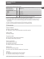
17. Accessories
Pressure adapters
Various pressure adapters
“Minimess“ Quick-Connect process connection system
Power supply
Battery charger
Connection cable
Test cable set with various connectors
Interface cable USB or RS-232
Pressure generation
Pneumatic test pumps
Hydraulic test pumps
Integral reservoir and pressure hoses
11069023 05/2006 GB/D
Service case
Test and measuring cases
Various test and calibration cases incl. test pump
Software
Calibration certificate Print-Tool “PrintCal“
Calibration software EasyCal “Standard“
WIKA Operating Instructions ProcessCalibrator
55
GB
ProzessKalibrator
CPH6000
D
Warnung!
Dieses Symbol warnt Sie vor Handlungen, die Schäden an
Personen oder am Gerät verursachen können.
56
WIKA Betriebsanleitung ProzessKalibrator
11069023 05/2006 GB/D
Information
Dieses Zeichen gibt Ihnen Informationen, Hinweise oder
Tipps.
ProzessKalibrator
CPH6000
Inhalt
11069023 05/2006 GB/D
1.
1.1
1.2
1.3
2.
3.
3.1
3.2
4.
4.1
4.2
4.3
5.
5.1
5.2
5.3
5.4
5.5
6.
6.1
7.
8.
8.1
8.2
8.3
9.
9.1
9.2
9.3
9.4
10.
10.1
10.2
10.3
10.4
10.5
10.6
10.7
11.
11.1
12.
13.
14.
15.
16.
17.
18.
Allgemeines
Allgemeine Sicherheitshinweise
Sicherheitshinweise bezüglich des CPH6000-Akkus
Allgemeine Produktinformationen
Laden des integrierten Akkus
Anschluss des Referenzsensors CPT6000
Mechanischer Anschluss
Elektrischer Anschluss
Elektrische Anschlüsse an der DigitalKonsole CPH6000
Elektrischer Anschluss eines potentialfreien Druckschalters
Elektrischer Anschluss eines 2-Leiter-Prüflings
Elektrischer Anschluss eines 3-Leiter-Prüflings
Grundeinstellungen und Anforderungen
Beispiele Prüf- und Kalibrieraufbauten (mit Testpumpen)
Anforderungen an Prüfaufbauten mit dem CPH6000
Geräteeinstellungen bez. einer Kalibrierung via Kalibriermodus
Einheit & Auflösung
Nullpunkt- bzw. Offsetkorrektur
Bedienoberfläche
Allgemeine Bedienhinweise bezüglich einer Konfiguration der
Arbeitsmodi
Menü-Struktur (MESSEN/KALIBRIEREN/SCHALTERTEST)
Display Darstellungen
Geräte-Statusmeldung kurz nach dem Einschalten
Display Inhalte der Arbeitsmodi
Inhalte des SETUP-MENÜS
Arbeitsmodi
Modus MESSEN
Modus MESSEN mit Prüfling
Modus KALIBRIEREN
Modus SCHALTER-TEST
SETUP-Zusatzmenüpunkt
Funktionen
CPH-Info
Referenz Sensor
Ref. Sensorliste
CPH-Einstellungen
Schnittstelle
Clear KalProg
Maßnahmen bei Störungen
Tabelle: Fehlerbeschreibung und Maßnahmen
Rekalibrierung und Wartung
Transport des Gerätes
Lagerung des Gerätes
Außerbetriebname
Technische Daten
Zubehör
Adressen
WIKA Betriebsanleitung ProzessKalibrator
58
59
61
62
64
66
66
67
68
69
70
71
72
72
72
74
74
75
76
76
77
78
78
79
82
84
84
86
88
96
98
98
99
100
101
102
103
103
104
104
106
106
107
107
108
110
111
57
D
ProzessKalibrator
CPH6000
1. Allgemeines
In den folgenden Kapiteln erhalten Sie nähere Informationen zum ProzessKalibrator
CPH6000 und seinen ordnungsgemäßen Einsatz. Sollten Sie weitere Informationen
wünschen, oder treten besondere Probleme auf, die in der Betriebsanleitung nicht
ausführlich behandelt werden, erhalten Sie Auskunft unter den auf der letzten Seite
aufgelisteten Adressen.
Bei der Werkskalibrierung der Instrumente wurde sich an entsprechende internationalen Normen orientiert.
Die Gewährleistungszeit für den ProzessKalibrator CPH6000 beträgt 24 Monate
nach den Allgemeinen Lieferbedingungen des ZVEI. Sämtliche Gewährleistungsansprüche verfallen, bei unsachgemäßer Handhabung bzw. bei Nichtbeachtung der
Betriebsleitungen oder bei dem Versuch das Gerät zu öffnen.
Außerdem weisen wir darauf hin, dass der Inhalt dieser Betriebsanleitung nicht Teil
einer früheren oder bestehenden Vereinbarung, Zusage oder Rechtsverhältnisses
ist oder diese abändern soll.
Sämtliche Verpflichtungen der WIKA Alexander Wiegand GmbH & Co. KG ergeben
sich aus dem jeweiligen Kaufvertrag und den Allgemeinen Geschäftsbedingungen
der WIKA Alexander Wiegand GmbH & Co. KG.
WIKA ist ein eingetragenes Warenzeichen der WIKA Alexander Wiegand GmbH &
Co. KG.
Firmen- oder Produktnamen, die in diesem Handbuch erwähnt werden, sind eingetragene Warenzeichen dieser Hersteller.
Zumutbare Änderungen aufgrund technischer Verbesserungen behalten wir uns vor.
Eine Vervielfältigung dieses Handbuches oder Teilen davon ist untersagt.
Firmware - Betriebsanleitungs-Versionsschlüssel
Manual
V 1.1
V 1.2
Firmware
31.08.05
34.10.05
© 2005 Copyright WIKA Alexander Wiegand GmbH & Co. KG
58
WIKA Betriebsanleitung ProzessKalibrator
11069023 05/2006 GB/D
D
ProzessKalibrator
CPH6000
1.1 Allgemeine Sicherheitshinweise
Dieses Gerät ist gemäß den Sicherheitsbestimmungen für elektronische Messgeräte gebaut und geprüft. Die Funktion und Betriebssicherheit des Gerätes kann nur dann gewährleistet werden,
wenn die nationalen Sicherheits- und Unfallverhütungsvorschriften sowie die Sicherheitshinweise der Betriebsanleitung beachtet
werden.
1. Das Gerät darf nur von dafür ausgebildeten und befugten Personen bedient
werden, die die Betriebsanleitung kennen und danach arbeiten können!
2. Die einwandfreie Funktion und Betriebssicherheit des Gerätes kann nur unter
den klimatischen Verhältnissen, die im Kapitel “Technische Daten“ spezifiziert
sind, eingehalten werden.
3. Das CPH6000 ist stets mit der, für ein elektronische Präzisionsgerät, erforderlichen Sorgfalt zu behandeln (Vor Nässe, Stößen, starken Magnetfeldern, statische Elektrizität und extremen Temperaturen schützen, keine Gegenstände in
das Gerät bzw. Öffnungen einführen). Gerät und Sensor müssen pfleglich behandelt werden (nicht werfen, aufschlagen, etc.). Stecker und Buchsen sind vor
Verschmutzung zu schützen.
4. Wird das Gerät von einer kalten in eine warme Umgebung transportiert, so kann
durch Kondensatbildung eine Störung der Gerätefunktion eintreten. In diesem
Fall muss die Angleichung der Gerätetemperatur an die Raumtemperatur vor
einer erneuten Inbetriebnahme abgewartet werden.
5. Konzipieren Sie die Beschaltung beim Anschluss an andere Geräte besonders
sorgfältig. Unter Umständen können interne Verbindungen in Fremdgeräten
(z.B. Verbindung GND mit Erde) zu nicht erlaubten Spannungspotentialen
führen, die das Gerät selbst oder ein angeschlossenes Gerät in seiner Funktion
beeinträchtigen oder sogar zerstören können.
6. Der Netzstecker des Lade-/Netzgerätes zum Laden des CPH6000-Akkus muss
immer zugänglich in einer Netzsteckdose stecken, das heißt, man muss ihn
jederzeit ohne Schwierigkeiten aus der Netzsteckdose ziehen können, jedoch ist
aus Sicherheitsgründen möglichst ohne angeschlossenem Netzteil zu arbeiten.
11069023 05/2006 GB/D
Bei Betrieb mit einem defekten Netzgerät (z.B. Kurzschluss von
Netzspannung zur Ausgangsspannung) können am Gerät lebensgefährliche Spannungen auftreten!
7. Das Messsignal der Referenz (bzw. des Prüflings) kann durch massive elektromagnetische Einstrahlung beeinflusst werden bzw. die Anzeige des Signals ganz
ausbleiben.
WIKA Betriebsanleitung ProzessKalibrator
59
D
ProzessKalibrator
CPH6000
Die Sicherheit des Benutzers kann durch das Gerät beeinträchtigt sein, wenn es
zum Beispiel:
Sichtbare Schäden aufweist.
Nicht mehr wie vorgeschrieben arbeitet.
Längere Zeit unter ungeeigneten Bedingungen gelagert wurde.
In Zweifelsfällen das Gerät grundsätzlich an den Hersteller zur Reparatur bzw.
Wartung einschicken.
12. Es dürfen am Gerät keine Veränderungen oder Reparaturen vom Kunden vorgenommen werden. Zur Wartung oder Reparatur muss das Gerät zum Hersteller eingesandt werden.
13. Ein anderer Betrieb als der in der folgenden Anleitung beschriebene oder
außerhalb der Spezifikationen, ist bestimmungswidrig und muss deshalb ausgeschlossen werden.
11069023 05/2006 GB/D
D
8. Die Displayfrontscheibe besteht aus Glas (das splittern kann). Ist ein Zerbrechen
der Scheibe während der Benutzung nicht vollständig auszuschließen, müssen
alle Personen in der näheren Umgebung des Gerätes, vor und während der
Benutzung eine Schutzbrille tragen.
9. Prüf-/und Kalibrieraufbauten sind immer im drucklosen Zustand (Atmosphäre)
aufzubauen und zu demontieren.
10. Wird der CPH6000-Drucksensor bei Applikationen mit Druckmedium Öl verwendet, so ist ein anschließender Einsatz bei Brennstoffen oder Gasen auszuschließen, da dies zu gefährlichen Explosionen und Gefahr für Mensch und
Maschine führen kann.
11. Wenn anzunehmen ist, dass das Gerät nicht mehr gefahrlos betrieben werden
kann, so ist es außer Betrieb zu setzen und vor einer Wiederinbetriebnahme
durch Kennzeichnung zu sichern.
60
WIKA Betriebsanleitung ProzessKalibrator
ProzessKalibrator
CPH6000
1.2 Sicherheitshinweise bezüglich des CPH6000-Akkus
Die Elektrolyte des CPH6000-Akkus sind brennbar. Bei sichtbarer
Leckage ist das Gerät von Zündquellen fernzuhalten und in absorbierende Tücher zu wickeln.
Bei Kontakt mit Akku-Elektrolyt ist das Elektrolyt mit viel sauberem Wasser zu entfernen.
Bei Augen ohne zu reiben.
Bei der Haut sollte außerdem Seife verwendet werden.
Es ist sofort ärztliche Hilfe aufzusuchen!
11069023 05/2006 GB/D
Im Falle eines Brandes sind die entstehenden Verbrennungsgase
reizend und giftig.
Es sind die für diesen Fall notwendigen Maßnahmen einzuleiten
und es ist sofort ärztliche Hilfe aufzusuchen!
WIKA Betriebsanleitung ProzessKalibrator
61
D
ProzessKalibrator
CPH6000
1.3 Allgemeine Produktinformationen
Einsatz
Der ProzessKalibrator CPH6000 vereint die Vorteile eines kompakten Handheld-Instrumentes mit der umfangreichen Funktionalität eines Labor-Kalibrierinstrumentes.
Hierdurch gestalten sich alltägliche Aufgaben im Feld wie Messen, Prüfen oder
Kalibrieren von Druckmessgeräten inkl. Zeugnisgenerierung und das Überprüfen
von Druckschaltern besonders einfach.
Referenz-Drucksensoren
Für den ProzessKalibrator CPH6000 stehen eine Vielzahl von Referenz-Drucksensoren mit einer Genauigkeit von 0,025 % und Messbereichen von 250 mbar
bis zu 1000 bar zur Auswahl, die schnell und ohne Werkzeug am Gerät ausgetauscht werden können. Der verwendete Drucksensor kann mittels eines
Anschlusskabels auch extern betrieben werden. Beim Einschalten des CPH6000
wird der angeschlossene Referenz-Drucksensoren automatisch erkannt, so dass
jegliche Konfiguration für ihn entfällt.
Geräte-Merkmale
Das Gerät verfügt über 3 Arbeitsmodi: MESSEN/KALIBRIEREN/SCHALTERTEST, die dem Anwender jeweils größtmöglichen Komfort entsprechend seiner
Anwendung bieten.
Zur Versorgung von Prüflingen und zum Einlesen deren Messsignale stehen
elektrische Ein- und Ausgänge zur Verfügung, die optional durch unverlierbare
Schutzkappen gegen raue Feldbedingungen geschützt werden können.
Im Arbeitsmodus MESSEN (mit Prüfling) und KALIBRIEREN werden die Messwerte des Referenz-Drucksensors und des Prüflings, sowie deren Abweichung
in der aktuellen Druckeinheit und in % dargestellt.
Hierdurch wird der Anwender direkt on-line informiert, ob der Prüfling die
Klassengenauigkeit einhält oder nicht. Der Unterschied zwischen diesen beiden
Modi ist, dass die Kalibrierdaten im KALIBRIEREN-Modus intern gespeichert
werden und später mittels Software (PrintCal oder EASYCal) in ein druckfähiges
Zeugnis überführbar sind.
Bezüglich des Datentransfer zu einem PC verfügt der Druck-Prozesskalibrator
CPH6000 über eine RS-232 und USB-Schnittstelle, die via Menü auswählbar
sind.
Die Stromversorgung des Gerätes erfolgt über den internen Lithium-Ionen Akku,
der mit dem im Lieferumfang befindlichem Ladegerät einfach aufgeladen werden kann.
62
WIKA Betriebsanleitung ProzessKalibrator
11069023 05/2006 GB/D
D
ProzessKalibrator
CPH6000
11069023 05/2006 GB/D
SETUP-Menü
Via SETUP-Taste gelangt man in das SETUP-Menü, indem der gewünschte
Arbeitsmodus (MESSEN/KALIBRIEREN/SCHALTERTEST) gewählt und konfiguriert, eine hinterlegte Funktion aufgerufen oder allgemeine Geräteeinstellungen
wie z. B.: die Menüsprache verändert werden kann.
WIKA Betriebsanleitung ProzessKalibrator
63
D
ProzessKalibrator
CPH6000
2. Laden des integrierten Akkus
Der Netzstecker des Lade-/Netzgerätes zum Laden der CPH6000-Akkus muss immer zugänglich in einer Netzsteckdose stecken, das heißt, man muss ihn jederzeit
ohne Schwierigkeiten aus der Netzsteckdose ziehen können, jedoch ist aus Sicherheitsgründen möglichst ohne angeschlossenem Netzteil zu arbeiten.
Bei Betrieb mit einem defekten Netzgerät (z.B. Kurzschluss von
Netzspannung zur Ausgangsspannung) können am Gerät lebensgefährliche Spannungen auftreten!
Das Gerät wir mit einem Akkuladezustand von 25 % - 50 % ausgeliefert und sollte
vor dem Arbeitseinsatz zuerst einmal vollständig geladen werden.
Der Akkukapazitätsstatus (Ladezustand in %) wird kurz nach dem Einschalten des
Gerätes angezeigt bzw. kann im “SETUP-Zusatzmenüpunkt CPH-Einstellungen“
(siehe Kapitel 10.5) in Erfahrung gebracht werden.
Die Temperatur während des Ladens muss unter 45 °C und über 10 °C liegen.
Ist das Netzladegerät am CPH6000 angeschlossen, so wird der Akku
auch im ausgeschalteten Zustand des CPH6000s geladen.
Die Akkuladekapazität sollte während der Lagerung oder der
Versendung per Schiff zwischen 30 % - 50 % liegen.
Verwenden Sie nur das Ladegerät, das vom Hersteller zugelassen ist.
Wenn Sie ein Ladegerät nicht mehr verwenden, ziehen Sie seinen Netzstecker
aus der Steckdose. Lassen Sie den Akku nicht länger als einen Tag am Ladegerät angeschlossen, da eine zu starke Aufladung seine Lebensdauer verkürzen
kann. Sollt der Akku nach 24 Std. nicht vollständig geladen sein, sollte der Hersteller kontaktiert werden. Bei Nichtgebrauch entlädt sich ein voll aufgeladener
Akku mit der Zeit.
64
WIKA Betriebsanleitung ProzessKalibrator
11069023 05/2006 GB/D
D
ProzessKalibrator
CPH6000
Extreme Temperaturen haben einen nachteiligen Einfluss auf das Laden Ihres
Akkus. Deshalb kann zunächst ein Abkühlen oder Aufwärmen des Akkus
erforderlich sein.
D
Wenn der Akku beinahe vollständig entladen ist, erscheint in der unteren InfoLeiste der Hinweis “low BAT“. Bei 0 % Akkukapazität schaltet sich das Gerät
automatisch ab und muss mit dem Ladegerät wieder geladen werden.
Benutzen Sie kein schadhaftes oder abgenutztes Ladegerät.
Bewahren Sie das Gerät möglichst zwischen 15 °C und 35 °C auf.
Ein Gerät mit einem kalten oder warmen Akku funktioniert unter Umständen nur
eingeschränkt.
11069023 05/2006 GB/D
Li-Ionen-Akkus funktionieren insbesondere unter 0 °C nur eingeschränkt.
WIKA Betriebsanleitung ProzessKalibrator
65
ProzessKalibrator
CPH6000
3. Anschluss des Referenzsensors CPT6000
Nur Sensoren der CPT6000-Serie verwenden! Mit anderen Sensoren kann es zur Zerstörung des Messgerätes und des Sensors
kommen. Zum Sensorwechsel Gerät ausschalten. Den Sensor vor
dem Einschalten des Gerätes anstecken, sonst wird er vom Gerät
evtl. nicht richtig erkannt.
Zum Zeitpunkt des Einschaltens des CPH6000 muss sich der
CPT6000-Drucksensor in der selben Einbaulage wie bei der späteren Messung befinden und darf nicht mit Druck beaufschlagt
sein, sondern muss an Atmosphärendruck liegen.
Im oberen Teil des Sensorgehäuses unter der Kunststoffverschraubung befindet sich, bei Überdruck- bzw. relativ Drucksensoren, das Loch für den Druckausgleich. Diese Öffnung (mit
integrierter Membrane) muss unbedingt frei bleiben!
D
3.1 Mechanischer Anschluss des CPT6000 Drucksensors am CPH6000
Handschnellspannverschluss
für ein einfaches
Wechseln des
Sensors.
6-Kant-Verdrehschutzsteg
66
WIKA Betriebsanleitung ProzessKalibrator
11069023 05/2006 GB/D
Zum mechanischen Anschluss ist der CPT6000-Drucksensor mit dem Anschlussgewinde voran in die sechseckige Sensorhalterung am Gerät zu stecken, so dass
der 6-Kant-Verdrehschutzsteg des CPT6000 passgenau in der Sensorhalterung
sitzt. Anschließend ist der Sensor mit der Handschnellspannverschlussschraube zu
sichern. (Festziehen = im Uhrzeigersinn drehen; lösen = gegen den Uhrzeigersinn
drehen)
ProzessKalibrator
CPH6000
3.2 Elektrischer Anschluss des CPT6000 Drucksensors am CPH6000
a) Elektrischer Standard Anschluss
D
Elektrisch wird der CPT6000-Drucksensor via eines Rundsteckverbinders
M12 x 1,5 mit Schraubverschluss am CPH6000 angeschlossen.
Anschlusskabel für
CPT6000-Drucksensor
Zum elektrischen Anschluss eines CPT6000-Drucksensors ist die Steckverbindung am Sensor gemäß der Orientierungsführung zusammenzustecken und durch
die Überwurfhülse zu sichern (Überwurfhülse ohne größeren Kraftaufwand in
Uhrzeigersinn drehen). Zum lösen der Verbindung ist die Überwurfhülse gegen den
Uhrzeigersinn zu drehen und beim Abstecken des Sensors nicht am Kabel ziehen,
sondern nur an der Steckerhülse.
b) Elektrischer Anschluss mittels Verlängerungskabel für den externen
Betrieb / Einsatz des CPT6000-Drucksensors
Es ist nur das original WIKA Verlängerungskabel für den externen
Betrieb des CPT6000-Drucksensors zu verwenden und maximal
nur ein Kabel.
11069023 05/2006 GB/D
Die Steckverbindungen sind
gemäß den Anweisungen unter
a) anschließen bzw. zu öffnen.
WIKA Betriebsanleitung ProzessKalibrator
67
ProzessKalibrator
CPH6000
4. Elektrische Anschlüsse an der DigitalKonsole CPH6000
Am oberen Ende des CPH6000 befinden sich alle elektrischen Anschlüsse (siehe
nachfolgende Abbildung).
Versorgungsspannung 24 V*
(via Menü aktivierbar)
Messeingang*
Spannung
Messeingang*
Strom bzw. Schaltertest
Netzanschluss-/Ladebuchse
(Akku wird automatisch
geladen)
Schnittstelle; USB oder
RS-232 (via Menü umschaltbar)
Anschlusskabel für den
CPT6000-Drucksensor
* Anschlüsse: 4 mm Laborbuchsen
An allen elektrischen Anschlussbuchsen dürfen nur Original
WIKA-Komponenten angeschlossen werden. (An der Netz-/Ladebuchse nur das WIKA Ladegerät, an der Laborbuchsen nur die
WIKA Prüfkabel und an der Schnittstellenbuchse nur das WIKA
RS-232 bzw. USB-Schnittstellenkabel).
Alle elektrischen Verbindungen sind im ausgeschalteten Zustand
des CPH6000s herzustellen bzw. zu trennen und außerdem ist
sicher zu stellen, dass die am Netzgerät angegebene Betriebsspannung mit der örtlichen Netzspannung übereinstimmt. Die
Messeingänge dürfen nicht elektrisch überlastet werden (siehe
Technische Daten) und bei vorhandener Eigenversorgung des
Prüflings ist die interne 24 V Versorgung via Menü auszuschalten.
Ist das CPH6000 für ein Einlesen von Prüflingen mit Spannungsausgang z.B.: 0-1 V / 0-2 V / 0-5 V / 0-10 V eingestellt und kein
Prüfling am Messeingang (Spannung) angeschlossen, so wird im
Display ein Wert ungleich Null für den Prüfling angezeigt. Dies
ist kein Fehler, sondern basiert auf den elektrischen Aufbau des
Messeinganges.
68
WIKA Betriebsanleitung ProzessKalibrator
11069023 05/2006 GB/D
D
ProzessKalibrator
CPH6000
Die internen 24 V Versorgungsspannungen sind nicht kurzzuschließen bzw. ist der max. Ausgangstrom von 50 mA durch die
Beschaltung nicht zu überschreiten. (Außerdem sollten 20 mA
nicht unterschritten werden, um eine korrekte Strommessung
sicher zu stellen.)
4.1 Elektrischer Anschluss eines potentialfreien Druckschalters
An das CPH6000 sind nur potentialfreie (passive) Schalter gemäß
Zeichnung mittels mitgelieferten Prüfkabels anzuschließen.
Eine Einspeisung von Strom oder Spannung kann zur Zerstörung
des CPH6000s führen.
11069023 05/2006 GB/D
Potentialfreie
Schalter
WIKA Betriebsanleitung ProzessKalibrator
69
D
ProzessKalibrator
CPH6000
4.2 Elektrischer Anschluss eines 2-Leiter-Prüflings
Vor dem Anschluss eines Prüflings sind die Hinweise unter
Kapitel 4. “Elektrische Anschlüsse an der DigitalKonsole
CPH6000“ zu lesen und nachfolgend zu beachten.
D
Anschlussplan z.B. eines WIKA Druckmessumformers (2-Leiter Ausführung) der überprüft / kalibriert werden soll.
Beispiele für den Fall, dass der Prüfling ein WIKA DMU mit mA-Signal ist:
b) bei vorhandener Eigenversorgung
11069023 05/2006 GB/D
a) ohne Eigenversorgung
(24 V müssen via Menü aktiviert werden;
siehe Kapitel 9.1 - 9.4)
70
WIKA Betriebsanleitung ProzessKalibrator
ProzessKalibrator
CPH6000
4.3 Elektrischer Anschluss eines 3-Leiter-Prüflings
Vor dem Anschluss eines Prüflings sind die Hinweise unter
Kapitel 4. “Elektrische Anschlüsse an der DigitalKonsole
CPH6000“ zu lesen und nachfolgend zu beachten.
Anschlussplan z.B. eines WIKA Druckmessumformers (2-Leiter Ausführung) der überprüft / kalibriert werden soll.
Beispiele für den Fall, dass der Prüfling ein WIKA DMU mit mA-Signal ist:
a) ohne Eigenversorgung
(24 V müssen via Menü aktiviert werden;
siehe Kapitel 9.1 - 9.4)
b) bei vorhandener Eigenversorgung
Beispiele für den Fall, dass der Prüfling ein WIKA DMU mit Volt-Signal ist:
b) bei vorhandener Eigenversorgung
11069023 05/2006 GB/D
a) ohne Eigenversorgung
(24 V müssen via Menü aktiviert werden;
siehe Kapitel 9.1 - 9.4)
WIKA Betriebsanleitung ProzessKalibrator
71
D
ProzessKalibrator
CPH6000
5. Grundeinstellungen und Anforderungen
5.1 Beispiele: Prüf- und Kalibrieraufbauten (mit Testpumpen)
mA
Prüfling
(elektrisch)
Prüfling (mechanisch)
5.2 Anforderungen an Prüfaubauten mit dem CPH6000
Akkukapazität
Vor dem Arbeitsbeginn sollte das Gerät kurz eingeschaltet
werden, um festzustellen, ob der Akku über einen ausreichenden
Ladezustand verfügt. (Akkukapazität in %). Die Akkukapazität
wird durch eine Geräte-Statusmeldung kurz nach dem Einschalten angezeigt (Siehe Kapitel 8.1). 100 % Akkukapazität ermöglichen die Arbeit mit dem Gerät für ca. 8 Std.
72
WIKA Betriebsanleitung ProzessKalibrator
11069023 05/2006 GB/D
D
ProzessKalibrator
CPH6000
Als erstes sind die Prüfaufbauten mechanisch und ggf. elektrisch (gemäß den vorhergehenden Kapiteln) zu verbinden / aufzubauen.
Vor dem Einschalten des CPH6000 ist sicherzustellen, dass sich der Prüfaubau im
drucklosen Zustand (System belüftet zu Atmosphäre) befindet und die Geräte die
korrekte Einbaulage / Positon aufweisen.
Besonders kleine Messbereiche z.B. < 1 bar sind Lageabhängig
(d.h. die Lage beeinflusst maßgeblich das Messsignal). Dies kann,
falls erforderlich, mittels der Tara-Funktion kompensiert werden
(Siehe Kapitel 10.1 “SETUP-Zusatzmenüpunkt Funktionen“).
Absolutdruck-Messbereiche < 1 bar absolut befinden sich an
Atmosphäre in einem Überlastzustand. Deshalb erscheint im
Display kein Messwert sondern nur 3 Striche als Zeichen eines
Druckes außerhalb des Messbereiches des angeschlossenen
Sensors. Wird der Druck vermindert, so dass er innerhalb des
zulässigen Messbereiches liegt, so erscheint im Display der
Messwert. Da Absolutdruck-Messbereiche < 1 bar absolut an
Atmosphärendruck bereits überlastet sind, sind für diese
Messbereiche die Überlast-Zeitdauerfunktion im SETUP-Menü
punkt: Referenz Sensor (siehe Kapitel 10.3) deaktiviert.
Höhendifferenz-Kompensation
Existiert zwischen Referenz (CPH6000-Sensor) und Prüfling ein größerer
Höhenunterschied, so kann ein Druckunterschied basierend auf einer Mediumssäule via Menü automatisch kompensiert werden.
(Siehe Kapitel 10.5 “SETUP-Zusatzmenüpunkt CPH-Einstellungen“)
11069023 05/2006 GB/D
Hinweis: Nach dem Einschalten des CPH6000s erscheint kurz eine GeräteStatusmeldung mit der aktuellen Einstellung.
WIKA Betriebsanleitung ProzessKalibrator
73
D
ProzessKalibrator
CPH6000
5.3 Wichtige Geräteeinstellungen bezüglich einer Kalibrierung via
Kalibriermodus
Kalibrier-Datum
Das Gerät verfügt über eine integrierte Echtzeituhr mit Datum. Das aktuelle
Datum einer Kalibrierung wird später auf dem Kalibrierzeugnis mit angegeben.
Vor dem Beginn einer Kalibrierung ist sicher zustellen, dass das interne Datum
des CPH6000s korrekt ist.
(Siehe Kapitel 10.5 “SETUP-Zusatzmenüpunkt CPH-Einstellungen“)
Hinweis: Nach dem Einschalten des CPH6000s erscheint kurz eine GeräteStatusmeldung mit der aktuellen Einstellung.
Kalibrier-Temperatur
Auf Kalibrierzeugnissen von Druckmessgeräten wird neben den Kalibrierdaten
immer auch die Umgebungstemperatur angegeben, die bei der Kalibrierung
vorherrschte. Deshalb kann die aktuelle Umgebungstemperatur via Menü in das
CPH6000 eingegeben werden und wird später auf dem Kalibrierzeugnis mit
aufgeführt. Vor dem Beginn einer Kalibrierung ist sicher zustellen, dass der
Temperaturwert im CPH6000 der Umgebungstemperatur entspricht.
(Siehe Kapitel 10.5 “SETUP-Zusatzmenüpunkt CPH-Einstellungen“)
Hinweis: Nach dem Einschalten des CPH6000s erscheint kurz eine GeräteStatusmeldung mit der aktuellen Einstellung.
5.4 Einheit und Auflösung
Nach der Wahl eines der Haupt-Menüpunkte des SETUP-Menüs (SETUP-Taste
drücken), wie z. B.: MESSEN, KALIBRIEREN oder SCHALTERTEST kann jeweils
via Menüpunkt: “Einheit“ und seinem zugehörigen Untermenü (Cursor auf “Einheit“
und Richtungspfeil rechts oder links drücken) die Einheit und Auflösung eingestellt
werden. (Siehe Kapitel 9: “Arbeitsmodi“).
11069023 05/2006 GB/D
D
74
WIKA Betriebsanleitung ProzessKalibrator
ProzessKalibrator
CPH6000
Tabelle der verfügbaren Einheiten inkl. Umrechnungsfaktor bezogen auf die
Einheit: bar:
bar
mbar
hPa
psi
inHg (0 °C)
cmHG (0 °C)
MPa
kPa
Pa
mH2O (4 °C)
cmH2O (4 °C)
mmH2O (4 °C)
kg/cm2
inH2O (60 °C)
mmH2O (0 °C)
D
1.00000E+00
1.00000E-03
1.00000E-03
6.89475E-02
3.37690E-02
1.33322E-02
1.00000E+01
1.00000E-02
1.00000E-05
9.80670E-02
9.80670E-04
9.80670E-05
9.80665E-01
2.48800E-03
1.33322E-03
5.5 Nullpunkt- bzw. Offsetkorrektur
Nullpunktkorrektur von Überdrucksensoren
Ist der Messwert des CPH6000s bei angeschlossenem Überdrucksensor und
belüfteten Prüfaufbau ungleich Null, so kann durch ein zweimaliges Drücken der
CLEAR - Taste (innerhalb von 5 sec.) der Nullpunkt korrigiert werden (maximale
zugelassene Korrekturwert ist in Größe der 2-fachen Klassengenauigkeit).
11069023 05/2006 GB/D
Offfsetkorrektur von Absolutdrucksensoren
Bei Absolutdrucksensoren kann eine Offsetkorrektur via Menü vorgenommen
werden.
(Siehe Kapitel 10.3 “SETUP-Zusatzmenüpunkt Referenz Sensor“)
WIKA Betriebsanleitung ProzessKalibrator
75
ProzessKalibrator
CPH6000
6. Bedienoberfläche
D
SETUP-Menü
Numerischer
Eingabeblock
Auswahl &
EingabeAktivierung
1 Schritt
zurück
EingabeQuittierung
Löschen der
Eingabe
Ein / Aus
6.1 Allgemeine Bedienhinweise bezüglich einer Konfiguration der Arbeitsmodi:
Parameter-Auswahl
aus Liste
Eingabe der Parameter
+ Eingabequittierung
+
ENTER
Parameter-Auswahl
aus Untermenü
76
Auswahl der aktuellen
Cursor-Position innerhalb
des Menüs
WIKA Betriebsanleitung ProzessKalibrator
11069023 05/2006 GB/D
}
ProzessKalibrator
CPH6000
7. Menü-Struktur (Arbeitsmodi)
Mittels SETUP-Menü lässt sich der gewünschte Arbeitsmodus leicht einstellen
(siehe nachfolgende Zeichnung).
D
SETUP-Menü
SETUP
SELECT
SELECT
SELECT
SELECT
Konfiguration
SELECT
Arbeitsmodi
11069023 05/2006 GB/D
SELECT
opt.
Wechsel der Prüflingsanzeige möglich
(Druck <--> elektrisches Signal) via
WIKA Betriebsanleitung ProzessKalibrator
77
ProzessKalibrator
CPH6000
8. Display Darstellungen
8.1 Geräte-Statusmeldung kurz nach dem Einschalten des CPH6000
Direkt nach dem Einschalten des Gerätes erscheint für einen kurzen Moment
folgende Statusmeldungen:
a->
b->
c->
d->
e->
f->
a) Die Versorgungsspannung von 24 V (verfügbar am oberen Ende des Gerätes)
kann während der Konfiguration eines jeden Arbeitsmodus ein-/bzw. ausgeschaltet werden. Wird sie für eine Messung nicht benötigt, so sollte sie ausgeschaltet werden, um Energie zu sparen.
b) Aktuelle Akkukapazität (siehe Kapitel 10.5)
c) Höhendifferenz in [mm]
Im Menü: “SETUP \ CPH-Einstellungen“ eingestellte Höhendifferenz zwischen
Prüfling und CPT6000-Drucksensor. Dieser Wert bewirkt eine automatische
Korrektur-Berechnung, um eine Druckdifferenz, basierend auf einer Mediumssäule, zu eliminieren. Dieser Wert muss für den nachfolgenden Messvorgang
stimmen bzw. im “SETUP-Menü \ CPH-Einstellungen“ entsprechend angepasst
werden (siehe Kapitel 5.2).
d) Temperatur in [°C]
Im Menü: “SETUP \ CPH-Einstellungen“ eingestellte Temperatur (Umgebungstemperatur), die später auf dem Kalibrierzeugnis vermerkt wird. Dieser Wert
muss für den nachfolgenden Messvorgang im Kalibriermodus stimmen bzw. im
“SETUP-Menü \ CPH-Einstellungen“ entsprechend angepasst werden (Siehe
Kapitel 5.2).
e) Aktuelles Datum der integrierten Echtzeituhr
Im Menü: “SETUP \ CPH-Einstellungen“ eingestelltes Datum der Echtzeituhr,
das später mit auf dem Kalibrierzeugnis vermerkt wird.
78
WIKA Betriebsanleitung ProzessKalibrator
11069023 05/2006 GB/D
D
ProzessKalibrator
CPH6000
Dieser Wert muss für den nachfolgenden Messvorgang im Kalibriermodus
stimmen bzw. im “SETUP-Menü \ CPH-Einstellungen“ entsprechend angepasst
werden (Siehe Kapitel 5.2).
f) Kalibrierdatum der elektrischen Messeingänge des CPH6000 (Jahr/Monat/Tag)
Nach der Statusmeldung erscheint die Oberfläche des zuletzt eingestellten Arbeitsmodus (siehe nachfolgendes Kapitel 8.2).
8.2 Display-Inhalte der Arbeitsmodi
8.2.1 Arbeitsmodus: MESSEN
Nach dem erstmaligen Einschalten des CPH6000s mit angeschlossenem CPT6000Drucksensor befindet sich das Gerät (nach einer kurzen Statusmeldung) im Modus:
MESSEN (siehe nachfolgendes Bild).
Display: MESSEN nur mit Referenz-Drucksensor (ohne Prüfling)
Messbereich des
Referenz-Drucksensors CPT6000
(der aktuell angeschlossen ist)
Druckeinheit
(via Menü
einstellbar)
11069023 05/2006 GB/D
Aktueller Messwert des
Referenz-Drucksensors
WIKA Betriebsanleitung ProzessKalibrator
79
D
ProzessKalibrator
CPH6000
Display: MESSEN mit Prüfling
Druckeinheit
(des Prüflings)
Messbereich des Prüflings
Aktueller Messwert des Prüflings
Abweichung/ Differenz zwischen
Referenz und Prüfling in der aktuellen
Druckeinheit und in % von der Messspanne (% FS) bzw. % vom Messwert
(%rd)
Drucksignal (Prüfling)
P
umschaltbar
I/U
Original Ausgangsignal des Prüflings
Aktueller Wert des Ausgangssignals
Elektr. Signal (Prüfling)
11069023 05/2006 GB/D
D
Im Modus MESSEN kann parallel zum Referenz-Druckmesswert auch ein Prüfling
zur Anzeige gebracht werden (siehe nachfolgendes Bild).
Bezüglich der Konfiguration siehe Kapitel 9.1 und 9.2.
80
WIKA Betriebsanleitung ProzessKalibrator
ProzessKalibrator
CPH6000
8.2.2 Arbeitsmodus: KALIBRIEREN
Im Modus KALIBRIEREN sind die Daten über der gestrichelten Trennlinie die selben wie im Modus “MESSEN mit Prüfling“ (siehe 8.2.1).
{
CPT6000-Referenz-Drucksensor
{
Prüfling
Differenz von Referenz-Prüfling
Sollwert der Kalibrierung
Istwert der Kalibrierung
P-01: Prüfling Nr. 1
}
<01>: Prüfschritt Nr. 1
ID-Nr: IDENT Nummer des Prüfling
P
Drucksignal (Prüfling)
umschaltbar
I/U
Original Signal des Prüflings
Elektr. Signal (Prüfling)
8.2.3 Arbeitsmodus: SCHALTERTEST
Im Modus: SCHALTERTEST werden neben dem Referenz-Drucksensor (siehe Modus MESSEN) Angaben zum Status und zu den Schaltpunkten des Druckschalters
angezeigt.
11069023 05/2006 GB/D
CPT6000-Referenz-Drucksensor
Aktueller Schaltzustand / Status
des Druckschalters
Schaltpunkt des Öffnens
Schaltpunkt des Schließens
Hysterese / Abstand zwischen
Schließen und Öffnen des Schalters
WIKA Betriebsanleitung ProzessKalibrator
{
Druckeinheit
(via Menü
einstellbar)
81
D
ProzessKalibrator
CPH6000
8.3 Inhalt des SETUP-MENÜS
SETUP
D
a ->
b ->
c ->
d ->
e ->
f ->
g->
h->
i->
j->
a) MESSEN: Arbeitsmodus MESSEN
Zum Messen von Arbeits-/Prozessdrücken
Für Vergleichsmessungen bzw. Kalibrierung (ohne Speicherung der Daten)
von mechanischen* & elektrischen Druckmessgeräten (Versorgung &
Anzeige des Prüflings durch das CPH6000)
Weitere Informationen siehe Kapitel 9.1 und 9.2
b) KALIBRIEREN: Arbeitsmodus KALIBRIEREN
Zur Kalibrierung von mechanischen* & elektrischen Druckmessgeräten vor
Ort (ohne PC). Hierbei werden die Datensätze von bis zu 16 Prüflingen mit
jeweils bis zu 32 Prüfschritten inkl. Datum & Zeit im CPH6000 gespeichert.
Weitere Informationen siehe Kapitel 9.3
c) SCHALTERTEST: Arbeitsmodus SCHALTERTEST
Für die komfortable Überprüfung von Druckschaltern inkl. automatische
Berechnung der Schalthysterese
Weitere Informationen siehe Kapitel 9.4
* Bei mechanischen Zeigerinstrumenten muss der Messwert des Prüflings via numerischen Eingabeblock eingegeben werden.
82
WIKA Betriebsanleitung ProzessKalibrator
11069023 05/2006 GB/D
Die Kalibrierdaten können mittels der Software PrintCal oder EasyCal
in ein druckfähiges Zeugnis überführt werden.
ProzessKalibrator
CPH6000
d) Funktionen: Arbeits-Funktionen wie:
Tara: Offsetkorrektur des Referenzdruckmesswertes
Min/Max: Minimum/Maximum Speicher
Alarm: Min/Max-Alarm (visuell & akustisch)
Filter: Beruhigung / Glättung des Referenzsensorsignals
Weitere Informationen siehe Kapitel 10.1
D
e) CPH-Info: Allgemeine CPH6000 Gerätedaten wie:
Kalibrierdaten der elektrischen Messeingänge
Firmware-Nummer
Serien-Nr. des Gerätes
Weitere Informationen siehe Kapitel 10.2
f) Referenz Sensor: Daten des aktuell angeschlossenen Referenz-Drucksensors
wie:
Messbereich
Genauigkeitsklasse
Druckart des Sensors
Info falls Referenzsensor überlastet wurde
Kalibrierdaten des Referenzsensors
Weitere Informationen siehe Kapitel 10.3
g) Referenz Sensorliste:
Liste der gespeicherten Referenzsensoren, die angeschlossen werden können
und kalibriert sind.
Weitere Informationen siehe Kapitel 10.4
h) CPH Einstellungen:
Info: zur Akkukapazität
Einstellmöglichkeiten von: Menüsprache, Systemzeit / Systemuhr, DisplayHelligkeit, Powersave-Funktion (automatischer Energiesparmodus siehe
Kapitel 10.5)
Eingabemöglichkeiten:
- der Umgebungstemperatur während der Kalibrierung (siehe Kapitel 5.2)
- der vorhandenen Höhendifferenz zwischen Referenz-Drucksensor (siehe
Kapitel 5.2).
Weitere Informationen siehe Kapitel 10.5
11069023 05/2006 GB/D
i) Schnittstelle:
Auswahl zwischen USB und RS-232 Schnittstelle inkl. Einstellung der
Baudrate
Weitere Informationen siehe Kapitel 10.6
j) Clear KalProg:
Löschen aller gespeicherten Kalibrierdaten (Freigabe und Zurücksetzen aller
Speicherplätze
Weitere Informationen siehe Kapitel 10.7
WIKA Betriebsanleitung ProzessKalibrator
83
ProzessKalibrator
CPH6000
9. Arbeitsmodi
9.1 Modus MESSEN
1. SETUP-MENÜ aufrufen
SETUP
Drücke
(SETUP-Taste)
Auswahl
(Menü-Punkt)
2. MESSEN vorbereiten
SELECT
a
b
c
d, e
f
g
h
i
3. Modus: MESSEN
Bestätigung
(der Auswahl)
Auswahl
(Menü-Punkt);
Konfiguration, siehe
nächste Seite
SELECT
Bestätigung
(der Eingabe)
Referenz ->
Druckeinheit
(via Menü einstellbar)
84
11069023 05/2006 GB/D
D
WIKA Betriebsanleitung ProzessKalibrator
ProzessKalibrator
CPH6000
9.1 Modus MESSEN
Um das Gerät in den Modus “MESSEN“ zu überführen, ist wie auf der vorhergehenden Seite zu verfahren.
Nachfolgend nähere Erklärung zu Punkt: “2. MESSEN vorbereiten“
a: Prüflingsart bzw. Prüflingsmesssignal: [----] für Messen ohne Prüfling
b: Messbereichsanfang des Prüflings
c: Messbereichsende des Prüflings
d: Messunsicherheit des Prüflings in % FS (bez. auf die Spanne) oder % rd (bez.
auf den Messwert)
e: Messunsicherheit des Prüflings in %
f: Einheit & Auflösung (Untermenü)
Auswahl & Bestätigung (Standard-Einheit)
via
SELECT
Kundenspezifische-Einheit; bez. auf bar
(Eingabe via Numerischen Eingabeblock)
Auflösung der Anzeige im Arbeitsmodus
via
(zurück mit BACK )
Kurzinfo:
11069023 05/2006 GB/D
g: Messart des Prüflings (relativ oder absolut)
h: Prüfmedium (Pneumatik -> Gas & Hydraulik -> Öl)
i: Versorgungsspannung für Prüfling (an/aus) [Falls keine Fremdversorgung für
den Prüfling benötigt wird, sollte “AUS“ gewählt werden, um Energie zu
sparen]
xxx
Aktuelle Cursorposition; Wechsel via
} Parameter-Auswahl aus Liste bzw. Menü via
0.00
Parameter-Eingabe mittels Numerischen Eingabeblock
CLEAR
ENTER
Eingabe Quittierung
Löschen der Eingabe
WIKA Betriebsanleitung ProzessKalibrator
85
D
ProzessKalibrator
CPH6000
9.2 Modus MESSEN (mit Prüfling)
D
SETUP
1. SETUP-MENÜ aufrufen
Drücke
(SETUP-Taste)
Auswahl
(Menü-Punkt)
SELECT
2. MESSEN vorbereiten
a
b
c
d, e
f
g
h
i
Bestätigung
(der Auswahl)
Auswahl
(Menü-Punkt);
Konfiguration, siehe
nächste Seite
SELECT
3. Modus: MESSEN
Bestätigung
(der Eingabe)
Referenz ->
P
Abweichung ->
Drucksignal (Prüfling)
86
I/U
umschaltbar
Elektr. Signal (Prüfling)
WIKA Betriebsanleitung ProzessKalibrator
11069023 05/2006 GB/D
Prüfling ->
ProzessKalibrator
CPH6000
9.2 Modus MESSEN (mit Prüfling)
Soll das Gerät in den Modus “MESSEN“ (mit Prüfling ≅ Anzeige des Prüflingssignals als elektrisches Signal oder als Druck) überführt werden, um eine Vergleichsmessung / Kalibrierung ohne Messwertspeicherung durchzuführen, so ist wie auf
der vorhergehenden Seite zu verfahren.
Nachfolgend nähere Erklärung zu Punkt: “2. MESSEN vorbereiten“
a: Prüflingsart bzw. Prüflingsmesssignal [0 ... 20 mA / 4 ... 20 mA / 0 ... 1 V /
0 ... 2 V / 0 ... 5 V / 0 ... 10 V / bez. mechanisch für Zeigermanometer]
Wird eine Vergleichsmessung mit einem mechanischem Zeigerinstrument (Prüfling) durchgeführt, so ist der aktuelle Messwert des Zeigerinstrumentes via
Numerischen Eingabeblock einzugeben und mit Enter zu bestätigen.
b: Messbereichsanfang des Prüflings
c: Messbereichsende des Prüflings
d: Messunsicherheit des Prüflings in % FS (bez. auf die Spanne) oder % rd (bez.
auf den Messwert)
e: Messunsicherheit des Prüflings in %
f: Einheit & Auflösung (Untermenü)
Auswahl & Bestätigung (Standard-Einheit)
via
SELECT
Kundenspezifische-Einheit; bez. auf bar
(Eingabe via Numerischen Eingabeblock)
Auflösung der Anzeige im Arbeitsmodus
via
(zurück mit BACK )
Kurzinfo:
11069023 05/2006 GB/D
g: Messart des Prüflings (relativ oder absolut)
h: Prüfmedium (Pneumatik -> Gas & Hydraulik -> Öl)
i: Versorgungsspannung für Prüfling (an/aus) [Falls keine Fremdversorgung für
den Prüfling benötigt wird, sollte “AUS“ gewählt werden, um Energie zu
sparen]
xxx
Aktuelle Cursorposition; Wechsel via
} Parameter-Auswahl aus Liste bzw. Menü via
0.00
Parameter-Eingabe mittels Numerischen Eingabeblock
CLEAR
ENTER
Eingabe Quittierung
Löschen der Eingabe
WIKA Betriebsanleitung ProzessKalibrator
87
D
ProzessKalibrator
CPH6000
9.3 Modus KALIBRIEREN
D
SETUP
1. SETUP-MENÜ aufrufen
Drücke
(SETUP-Taste)
Auswahl
(Menü-Punkt)
SELECT
2. KALIBRIEREN vorbereiten
a
b
c
d
e
f
g, h
i
j
k
l
m
n, o
p
Bestätigung
(der Auswahl)
Auswahl
(Menü-Punkt);
Konfiguration, siehe
nächste Seite
SELECT
3. Modus: KALIBRIEREN
Bestätigung
(der Eingabe)
Referenz ->
Prüfling ->
P
Drucksignal (Prüfling)
88
I/U
umschaltbar
Nr. Prüfling & ->
Nr. Prüfpunkt
Elektr. Signal (Prüfling)
WIKA Betriebsanleitung ProzessKalibrator
11069023 05/2006 GB/D
Abweichung ->
ProzessKalibrator
CPH6000
9.3 Modus KALIBRIEREN
Um das Gerät in den Modus “KALIBIEREN“ zu überführen, ist wie auf der vorhergehenden Seite zu verfahren.
Nachfolgend nähere Erklärung zu Punkt: “2. KALIBRIEREN vorbereiten“
a: Nr. der Kalibrierung bzw. des Prüflings. (bis zu 16 Kalibrierungen mit jeweils bis
zu 32 Prüfschritten können vordefiniert bzw. gespeichert werden)
b: Prüflingsart bzw. Prüflingsmesssignal [0 ... 20 mA / 4 ... 20 mA / 0 ... 1 V /
0 ... 2 V / 0 ... 5 V / 0 ... 10 V / bez. mechan für Zeigermanometer]
c: ID-Nr. des Prüflings
d: Messstellen Nr. des Prüflings
e: Messbereichsanfang des Prüflings
f: Messbereichsende des Prüflings
g, h: Messunsicherheit des Prüflings in % FS (bez. auf die Spanne) oder % rd (bez.
auf den Messwert)
i: Einheit & Auflösung (Untermenü)
Auswahl & Bestätigung (Standard-Einheit)
via
SELECT
Kundenspezifische-Einheit; bez. auf bar
(Eingabe via Numerischen Eingabeblock)
Auflösung der Anzeige im Arbeitsmodus
via
(zurück mit BACK )
Kurzinfo:
11069023 05/2006 GB/D
j: Messart des Prüflings (relativ oder absolut)
k: Prüfmedium (Pneumatik -> Gas & Hydraulik -> Öl)
l: Versorgungsspannung für Prüfling (an/aus) [Falls keine Fremdversorgung für
den Prüfling benötigt wird, sollte “AUS“ gewählt werden, um Energie zu
sparen]
m: Nr. des Prüfpunktes x
n: optionale DKD-konforme Wartezeit [sec] (siehe unter 9.3)
o: Wert des Prüfpunktes x (Eingabe via Numerischen Eingabeblock)
(Prüfpunkt x+1 bzw. x-1 via “
“ aufrufbar)
p: Wahrer Wert des Prüflings (wird bei der Kalibrierung gespeichert)
xxx
Aktuelle Cursorposition; Wechsel via
} Parameter-Auswahl aus Liste bzw. Menü via
0.00
Parameter-Eingabe mittels Numerischen Eingabeblock
CLEAR
ENTER
Eingabe Quittierung
Löschen der Eingabe
WIKA Betriebsanleitung ProzessKalibrator
89
D
ProzessKalibrator
CPH6000
9.3 Modus KALIBRIEREN (die Prüfpunkte einer Kalibrierung vorbereiten)
1. Prüfpunkt
(definieren)
Kalibrierung / Prüfling Nr. 1
Auswahl vom Menüpunkt:
“Soll“-wert
Nr. des Prüfpunktes
Sollwert des Prüfpunktes
1. Prüfpunkt
(definert)
ENTER
}
Eingabe des Prüfpunktes (z.B.:
0 bar) via numerischen Eingabeblock & Bestätigung
mit
<---
Prüfpunkt Nr. 1 = 0 bar
<-- 2. Prüfpunkt aufrufen
2. Prüfpunkt
(definieren)
(mit
zurück zum vorhergehenden Prüfpunkt)
11069023 05/2006 GB/D
D
x. Prüfpunkt
(definieren)
90
WIKA Betriebsanleitung ProzessKalibrator
ProzessKalibrator
CPH6000
9.3 Modus KALIBRIEREN (die Prüfpunkte einer Kalibrierung vorbereiten)
Mit diesem Beispiel wird erklärt wie die einzelnen Prüfpunkte / Druckstufen vor
einer Kalilbrierung definiert werden. Es können bis zu 16 Kalibrierungen mit bis zu
32 Prüfschritten vorbereitet werden.
Aufruf des Menüpunktes:
Via SETUP & Auswahl des Menüpunktes: KALBRIEREN (bzw. siehe Kapitel 9.3)
Die gewünschten Prüfpunkte sind, wie auf der vorhergehenden Seite beschrieben
einzugeben.
Bei der Kalibrierung von Druckmessgeräten mit elektrischem Ausgangssignal
(Druckmessumformer/Transmitter) wird nach Anzeige der Referenz kalibriert, d.h.
der Druck ist immer so einzustellen, dass der Referenzwert exakt dem Sollwert
entspricht.
Da unter Umständen ein exaktes Einstellen des Druckes nich immer möglich ist,
wird neben dem Istwert (Prüflingswert) und dem Sollwert (Sollwert = Referenzwert)
auch der wahre Referenzwert gespeichert.
Mittels der Software: “PrintCal“ kann eine der beiden Kombinationen im Kalibrierzeugnis aufgelistet werden.
11069023 05/2006 GB/D
Wird nach DKD-Richtlinie kalibriert, so dürfen die Messwerte des jeweils nächsten Prüfpunktes erst nach einer bestimmten Zeit (bestehend aus Laständerungszeit und Beharrungszeit) von z.B.: 30 sec
übernommen/gespeichert werden (siehe Abb. A Kalibrierzyklus nach
DKD-Richtlinie 6-1 für Messunsicherheit > 0,6 % der Messspanne).
Abb. A
WIKA Betriebsanleitung ProzessKalibrator
91
D
ProzessKalibrator
CPH6000
D
optionale DKD-Wartezeit [sec]
Eingabe via Numerischen Eingabeblock
& Bestätigung mit
ENTER
Durch die Eingabe einer Wartezeit wird die Übernahme/Speicherung des Prüfpunktes für diese Dauer gesperrt. (Im obigen Beispiel müssen nach der Speicherung
des ersten Prüfpunkten 30 sec vergehen bis der zweite Prüfpunkt gespeichert
werden kann.)
Sollten alte Prüfpunkte gelöscht bzw. zurückgesetzt werden, da die
neue Kalibrierung weniger Prüfpunkte als die vorherige Prüfreihe
besitzt, ist einfach die “CLEAR“-Taste zu drücken. Hierdurch wird der
aktuelle und alle nachfolgenden Prüfpunke gelöscht bzw. zurückgesetzt. (Dieser Vorgang kann einige Sekunden dauern.)
11069023 05/2006 GB/D
Hinweis: Sollen alle gespeicherten Kalibrierdaten sämtlicher Kalibrierungen auf einmal gelöscht werden siehe Kapitel 10.7.
92
WIKA Betriebsanleitung ProzessKalibrator
ProzessKalibrator
CPH6000
11069023 05/2006 GB/D
D
WIKA Betriebsanleitung ProzessKalibrator
93
ProzessKalibrator
CPH6000
9.3 Modus KALIBRIEREN (die Kalibrierung eines Druckmessumformers)
1. Prüfpunkt
(z.B. 0 bar)
Referenz ->
Prüfling ->
Abweichung ->
Nr. Prüfling & ->
Nr. Prüfpunkt
ENTER
2. Prüfpunkt
(z.B. 1 bar)
Vorgegebener Sollwert
Nach Anzeige der Referenz
generieren (drucklosen Zustand
herstellen/Atmosphäre) und
mit
<-Messwerte des Prüfpunktes
speichern
Referenz ->
Prüfling ->
Abweichung ->
Vorgegebener Sollwert mittels
Druckerzeugung
nach Anzeige der Referenz
generieren
Nr. Prüfling & ->
Nr. Prüfpunkt
2. Prüfpunkt
Referenz ->
Prüfling ->
Abweichung ->
Nr. Prüfling & ->
Nr. Prüfpunkt
ENTER
x. Prüfpunkt
94
Messwerte des Prüfpunktes
speichern
(mit
BACK
einen Schritt zurück)
WIKA Betriebsanleitung ProzessKalibrator
11069023 05/2006 GB/D
D
ProzessKalibrator
CPH6000
9.3 Modus KALIBRIEREN (die Kalibrierung eines Manometers)
1. Prüfpunkt
(z.B. 0 bar)
D
Referenz ->
Vorgegebener Sollwert mittels
Druckerzeugung
nach Anzeige des Prüflings
generieren
Prüfling ->
Abweichung ->
Nr. Prüfling & ->
Nr. Prüfpunkt
2. Prüfpunkt
(z.B. 1 bar)
ENTER
Bei Sollwert = 0 ist der Kalibrieraufbau in drucklosen Zustand zu bringen/Atmosphäre
(Prüfling muss 0 bar anzeigen;
ggf. Nullpunktjustage) und
Messwerte des Prüfpunktes
mit
<--speichern
Referenz ->
Prüfling ->
Abweichung ->
Vorgegebener Sollwert mittels
Druckerzeugung
nach Anzeige des Prüflings
generieren
Nr. Prüfling & ->
Nr. Prüfpunkt
2. Prüfpunkt
Referenz ->
Prüfling ->
11069023 05/2006 GB/D
Abweichung ->
Nr. Prüfling & ->
Nr. Prüfpunkt
x. Prüfpunkt
WIKA Betriebsanleitung ProzessKalibrator
ENTER
Messwerte des Prüfpunktes
speichern
(mit
BACK
einen Schritt zurück)
95
ProzessKalibrator
CPH6000
9.4 Modus SCHALTERTEST
D
1. SETUP-Menü aufrufen
SETUP
Drücke
(SETUP-Taste)
Auswahl
(Menü-Punkt)
2. SCHALTERTEST
vorbereiten
SELECT
Bestätigung
(der Auswahl)
a
Auswahl
(Menü-Punkt);
Konfiguration, siehe
nächste Seite
b
3. Modus: SCHALTERTEST
SELECT
Bestätigung
(der Eingabe)
Referenz ->
Schaltpunkte -> {
Vor dem Druckschaltertest
96
Nach dem Druckschaltertest
WIKA Betriebsanleitung ProzessKalibrator
11069023 05/2006 GB/D
aktueller ->
Schaltzustand
ProzessKalibrator
CPH6000
9.4 Modus SCHALTERTEST
Um das Gerät in den Modus “SCHALTERTEST“ zu überführen, ist wie auf der vorhergehenden Seite zu verfahren.
Der Schaltertest ist nicht für elektronische Schalter, wie z. B.: PNPoder NPN-Schalter geeignet, sondern nur für mechanische, potential
freie Schalter.
Nachfolgend nähere Erklärung zu Punkt: “2. SCHALTERTEST vorbereiten“
a: Versorgungsspannung für Prüfling (an/aus) [Falls keine Fremdversorgung für
den Prüfling benötigt wird, sollte “AUS“ gewählt werden, um Energie zu
sparen]
b: Einheit & Auflösung (Untermenü)
Auswahl & Bestätigung (Standard-Einheit)
via
SELECT
Kundenspezifische-Einheit; bez. auf bar
(Eingabe via Numerischen Eingabeblock)
Auflösung der Anzeige im Arbeitsmodus
via
(zurück mit BACK )
Kurzinfo:
11069023 05/2006 GB/D
Die ermittelten Messewerte der beiden Schaltpunkte und der Hysterese können durch ein Drücken der Ziffer: “0“ zurückgesetzt werden.
xxx
Aktuelle Cursorposition; Wechsel via
} Parameter-Auswahl aus Liste bzw. Menü via
0.00
Parameter-Eingabe mittels Numerischen Eingabeblock
CLEAR
ENTER
Eingabe Quittierung
Löschen der Eingabe
WIKA Betriebsanleitung ProzessKalibrator
97
D
ProzessKalibrator
CPH6000
10. SETUP-Zusatzmenüpunkte
10.1 SETUP-Zusatzmenüpunkt: Funktionen
a -->
Menüpunkt auswählen
b -->
c --{
Eingabe via numerischen Eingabeblock
d -->
e -->
ENTER
Bestätigung der Eingabe
(Clear löscht die Eingabe bzw.
setzt den MIN/MAX-speicher
zurück)
a) Ref:
Aktueller Messwert des angeschlossenen CPT6000 Druck-Referenzsensors
b) Tara:
Offset-Funktion, die den aktuellen Messwert beeinflusst. Der eingegebene Wert
wird zum aktuellen Messwert addiert.
(z.B. Ref. 0.000 & Tara: 1.000 --> [neu] Ref. 1.000)
c) Min:/Max:
Minimum und Maximum-Wertspeicher
Der Speicher wird jeweils zurückgesetzt, indem mit dem Cursor auf den Wert
gegangen ( via
) und dann die Clear-Taste gedrückt wird.
d) Alarm:
Akustische und visuelle Alarmfunktion.
obere Alarmgrenze: > = x bar
untere Alarmgrenze: < = x bar
Ist der aktuelle Messwert außerhalb der eingestellten Alarmgrenzen, so ertönt
ein zyklischer Alarmton und die untere Statuszeile blinkt.
Aktivierung via:
Mit dem Cursor auf das Feld “<AUS>“ neben dem Wort Alarm gehen und
via
auf “<EIN>“ umstellen.
Deaktivierung via:
wieder auf “<AUS>“ zurückstellen
98
WIKA Betriebsanleitung ProzessKalibrator
11069023 05/2006 GB/D
D
ProzessKalibrator
CPH6000
e) Filter [1-5]:
Beruhigung/Glättung des Referenzsensorsignals
Bedeutung der Zahlenwerte:
1 = keine zusätzliche Glättung ... 5 = starke Glättung
D
10.2 SETUP-Zusatzmenüpunkt: CPH-INFO
a -->
b -->
c -->
In diesem Menüpunkt sind allgemeine Daten gelistet, wie:
a) Cal-Dat:
Kalibrier-Datum der Kalibrierung der elektrischen Messeingänge des CPH6000
(Jahr/Monat/Tag)
b) Firmware:
Version der Firmware des CPH6000
11069023 05/2006 GB/D
c) Serial Nr:
Serien Nummer des CPH6000
WIKA Betriebsanleitung ProzessKalibrator
99
ProzessKalibrator
CPH6000
10.3 SETUP-Zusatzmenüpunkt: Referenz Sensor
D
a -->
b --{
c -->
d -->
e -->
f -->
g -->
h -->
i -->
a) Sensor Nr:
Serien Nummer des aktuell angeschlossenen CPT6000-Druck-Referenzsensors
b) MB-Anfang / MB-Ende:
Messbereichsanfangswert und -endwert des aktuell angeschl. CPT6000-Sensors
c) Einheit:
Basis-Druckeinheit des CPT6000-Sensors
d) Klasse:
Genauigkeit der Messkette aus CPH6000 mit angeschl. CPT6000-Sensors
f) Überlast:
Zeitdauer für die der CPT6000-Sensor unzulässig überlastet wurde.
Ist hier ein Wert ungleich Null eingetragen, so ist es sehr wahrscheinlich, dass das Gerät nicht mehr seine spezifizierte Klassengenauigkeit
einhält. Aufschluss kann hier nur eine umgehende Rekalibrierungen
geben. (Bei Absolutdrucksensoren < 1 bar absolut ist diese Funktion
deaktiviert, da schon der Atmosphärendruck für diese Messbereiche
eigentlich eine Überlast darstellt)
g) Akt. Druck:
Aktueller Messwert des angeschlossenen CPT6000-Referenz-Drucksensors
100
WIKA Betriebsanleitung ProzessKalibrator
11069023 05/2006 GB/D
e) Messart:
Druckart des aktuell angeschl. CPT6000-Sensors (Überdruck (Relativdruck)
oder Absolutdruck)
ProzessKalibrator
CPH6000
h) Offset:
Dieser Menüpunkt erscheint nur, wenn der Referenz-Ducksensor des
CPH6000s ein Absolutdrucksensor ist.
Mittels diesen Menüpunktes kann der Messwert des Referenz-Ducksensors
korrigiert werden. Dies sollte jedoch möglichst nur nahe dem absoluten Nullpunkt und mittels einer Referenz, die mindestens 4 mal genauer ist, geschehen.
i) Kalibriert:
Kalibrierdatum des CPT6000-Sensors (Jahr/Monat/Tag)
10.4 SETUP-Zusatzmenüpunkt: Ref. Sensorliste
a -->
Auswahl
eines gelisteten Sensors
mit
b ->
c ->
Es werden von dem Gerät bis zu 5 CPT6000-Sensoren unterstützt und diese sind
in diesem Menü gelistet.
a) Aktuell angeschlossener CPT6000-Druck-Referenzsensor
b) Sensor-Liste der unterstützen (mit dem Gerät kalibrierten) CPT6000-Sensoren
11069023 05/2006 GB/D
c) Daten des Sensors, der mit dem Cursor angewählt wurde
(Datum:Jahr/Monat/Tag)
WIKA Betriebsanleitung ProzessKalibrator
101
D
ProzessKalibrator
CPH6000
10.5 SETUP-Zusatzmenüpunkt: CPH-Einstellungen
D
a -->
b -->
Auswahl Menüpunkt
c -->
d -->
e -->
Eingabe via numerischen Eingabeblock
f -->
g -->
h -->
i -->
ENTER
Bestätigung der Eingabe
(Clear löscht die Eingabe)
In diesem Menü befinden sich allgemeine Geräteeinstellungen wie:
a) Eingabemöglichkeit einer Umgebungstemperatur, die später mit auf dem
Kalibrierzeugnis angegeben wird.
b) Eingabemöglichkeit einer Höhendifferenz zwischen Referenz-Drucksensor und
Prüfling zur automatischen Korrektur (herausrechnen eines Druckes basierend
auf einer Mediumssäule)
c) Auswahl der Menüsprache (deutsch/englisch)
Hinweis: Der Wechsel der Sprache nimmt ca. 3 sec in Anspruch.
d) Datum des Systemuhr (Jahr/Monat/Tag)
e) Zeit der Systemuhr (Stunde/Minute/Sekunde)
f) Helligkeit der Hintergrundbeleuchtung des Displays
h) Powersave-Funktion (automatische Abschaltzeit von Hintergrundbeleuchtung
und interner 24 V Prüflings-Versorgungsspannung).
Wird das Gerät für die eingestellte Abschaltzeit nicht benutzt (keine Taste
102
WIKA Betriebsanleitung ProzessKalibrator
11069023 05/2006 GB/D
g) Kontrast des Display (nicht veränderbar)
ProzessKalibrator
CPH6000
gedrückt & keine Schnittstellenkommunikation), so werden Hintergrundbeleuchtung und die 24 V Prüflingsversorgung so lange abgeschaltet, bis eine beliebige
Taste (außer EIN/AUS) bestätigt bzw. das Gerät über Schnittstelle angesprochen
wird.
i) Aktuelle Akkukapazität
Bei 10 % erscheint im Display die Warnung einer geringen Akkukapazität
“low BAT“.
10.6 SETUP-Zusatzmenüpunkt: Schnittstelle
Markiert die aktuelle Einstellung
Auswahl der Schnittstelle
SELECT
Auswahl bestätigen
Wechsel zwischen Schnittstellenart & Baudrate
In diesem Menü wird die Schnittstelle konfiguriert. Sie kann als USB oder RS-232
ausgelegt werden.
Bezüglich der RS-232-Schnittstelle kann zwischen 3 Baudraten gewählt werden
mit festen 8 genutzten Datenbits, keiner Parität und 1 Stop-Bit.
10.7 SETUP-Zusatzmenüpunkt: CLEAR KalProg
11069023 05/2006 GB/D
Wird der SETUP-Menüpunkt “CLEAR KalProg“ mit dem Fokus angewählt und
2x die SELECT-Taste betätigt, so werden sämtliche gespeicherten Kalibrierdaten
gelöscht bzw. zurückgesetzt.
Der Status des Löschvorganges (einige Sekunden) wird links in der
unteren Info-Zeile angezeigt.
WIKA Betriebsanleitung ProzessKalibrator
103
D
ProzessKalibrator
CPH6000
11. Maßnahmen bei Störungen
Können Störungen mit der Hilfe der Betriebsanleitung nicht beseitigt werden, ist das Gerät unverzüglich außer Betrieb zu
setzen und der Hersteller ist zu kontaktieren.
D
Reparaturen dürfen nur vom Hersteller durchgeführt werden.
Eingriffe und Änderungen am Gerät durch den Betreiber sind
unzulässig.
Bei Störungen die auf Defekte an der elektrischen oder pneumatischen/hydraulischen Ausrüstung zurückzuführen sind, muss das Bedienpersonal unverzüglich
die Vorgesetzten informieren und qualifiziertes sowie autorisiertes Fachpersonal für
Instandhaltung hinzuziehen.
11.1 Tabelle: Fehlerbeschreibung und Maßnahmen
Fehlerart
Maßnahmen
II. Der Bildschirm ist dunkel und die
Massnahmen zu Fehlerart I zeigen
keine Wirkung.
Überprüfen Sie, ob das Ladegerät
richtig angeschlossen ist und lassen Sie
durch autorisiertes Fachpersonal überprüfen, ob die Versorgungsspannung
korrekt ist.
III. Funktionsstörungen während der
Bedienung.
Gerät ausschalten und nach 5 Sekunden wieder einschalten.
IV. Es ertönt ein zyklischer Signalton
und in der unteren Infoleiste erscheint der Hinweis “Messbereich“
Der aktuelle Druckwert ist leicht (2 10 %) außerhalb des zulässigen Druckberereiches. Der Druck ist geeignet
anzupassen.
104
WIKA Betriebsanleitung ProzessKalibrator
11069023 05/2006 GB/D
Internen Akku mittels Ladegerät auflaI. Nach dem Einschalten des Gerätes,
erscheint nach 10 Sekunden kein
den.
Messwert, sondern der Bildschirm ist
über die gesamte Fläche dunkel.
ProzessKalibrator
CPH6000
Fehlerart
Maßnahmen
V. Es ertönt ein zyklischer Signalton und Der aktuelle Druckwert ist mehr als
anstatt Messwert erscheinen nur
10 % außerhalb des zulässigen DruckStriche im Display.
bereiches. Der Druck ist umgehend
geeignet anzupassen.
VI. In der unteren Infoleiste des Display
erscheine die Meldung “low BAT“.
Die Akku-Ladekapazität ist kleiner
10 %. Das Gerät mit dem zugehörigem
Ladegerät aufladen.
VII. Die Hintergrundbeleuchtung und
die internen 24 V Prüflings-Versorgungsspannung sind plötzlich nicht
mehr vorhanden.
Beliebige Taste (außer EIN/AUS)
drücken um die Power Save-funktion
rückgängig zu machen ggf. Countdown-Zeit der Power Save vergrößern
(siehe Kapitel 10.5)
VIII. Der Prüfling (eingelesen via der mA- Überprüfen Sie die Verkabelung;
bzw. V-Messeingänge) zeigt einen
überprüfen Sie, ob der Messbereich
falschen Wert bzw. reagiert nicht.
des Prüfling korrekt eingegeben wurde
oder bei einem Prüfling ohne Eigenversorgung, ob die 24 V Prüflingsversorgungsspannung aktiviert sind.
11069023 05/2006 GB/D
Weitere Hilfe erhalten Sie durch die WIKA-Abteilung der Prüf- und Kalibriertechnik.
WIKA Betriebsanleitung ProzessKalibrator
105
D
ProzessKalibrator
CPH6000
12. Rekalibrierung und Wartung
Es wird empfohlen, das Gerät in regelmäßigen Zeitabständen von ca. 12 Monaten
durch den Hersteller rekalibrieren zu lassen.
Jede werksseitige Rekalibrierung beinhaltet außerdem eine umfangreiche und
kostenfreie Überprüfung aller Systemparameter.
Wartung
Digitalgerät und Sensoren enthalten keinerlei Verschleißteile, so dass das Öffnen
der Geräte-Gehäuse nicht erforderlich ist und für die Aufrechterhaltung der Gewährleistungsansprüche unbedingt unterbleiben sollte.
Zur Reinigung der Folientastatur und des Displays dürfen nur handelsübliche
Kunststoff- oder Glasreiniger nach Anwendervorschrift verwendet werden. Hierzu
sollten wenig fusselnde Tücher gewählt werden.
Vor der Reinigung ist das Gerät ordnungsgemäß von jeglicher
Druckversorgung zu trennen, auszuschalten und vom Netz zu
trennen.
Die elektrischen Anschlüsse an der oberen Seite des Gerätes
sollten nicht mit dem feuchten Tuch in Berührung kommen.
13. Transport des Gerätes
Vor dem Versand des Gerätes müssen alle anhaftenden Mediumsreste entfernt werden. Dies ist besonders wichtig, wenn das
Medium gesundheitsgefährdend ist, wie z. B. ätzend, giftig,
krebserregend, radioaktiv, usw.
Vor dem Versand füllen sie bitte das, auf der WIKA-Homepage-Seite (www.wika.de
siehe Service/Warenrücksendung) befindliche, Warenrücksendung-Formular aus
und senden das Gerät unter Angabe der daraufhin erhaltenen Referenznummer an
die ebenfalls mitgeteilte Lieferadresse.
Bitte befolgen Sie folgende Anweisungen, um Schäden zu vermeiden.
1. Hüllen Sie das Gerät in eine antistatische Plastikfolie ein.
2. Plazieren Sie das Gerät unter Verwendung des Dämmmaterials so in einer
Transportkiste, dass sich zu allen Seiten der Transportkiste etwa gleichviel
Dämmmaterial befindet.
3. Fügen Sie der Kiste, wenn möglich, ein Beutel mit Trocknungsmittel bei.
106
WIKA Betriebsanleitung ProzessKalibrator
11069023 05/2006 GB/D
D
ProzessKalibrator
CPH6000
4. Stellen Sie sicher, dass die Sendung als Transport eines hochempfindlichen
Messgerätes gekennzeichnet ist.
D
14. Lagerung des Gerätes
Vor der Einlagerung des Gerätes müssen alle ggf. anhaftenden
Mediumsreste entfernt werden. Dies ist besonders wichtig, wenn
das Medium gesundheitsgefährdend ist, wie z. B. ätzend, giftig,
krebserregend, radioaktiv, usw.
Der Lagerungsort muss folgenden Bedingungen genügen:
Umgebungstemperatur: 0 bis 70 °C (Temperaturen über 40 °C können die
Akkukapazität beeinflussen)
Feuchtigkeit: 35 bis 85 % relative Feuchte (keine Betauung)
Vermeiden Sie folgende Einflüsse:
Direktes Sonnenlicht oder Nähe zu heißen Gegenständen
Mechanische Vibration, mechanischer Schock (hartes Aufstellen)
Ruß, Dampf, Staub und korrosive Gase
Explosionsgefärdete Umgebung, entzündliche Atmosphären
Bitte befolgen Sie folgende Anweisungen, um Schäden zu vermeiden.
1. Hüllen Sie das Gerät in eine antistatische Plastikfolie ein.
2. Platzieren Sie das Gerät unter Verwendung des Dämmmaterials so in der Kiste,
dass sich zu allen Seiten der Transportkiste etwa gleichviel Dämmmaterial
befindet.
3. Legen Sie der Kiste bei einer längeren Einlagerung (mehr als 30 Tage) ein Beutel
mit Trocknungsmittel bei.
15. Außerbetriebnahme
11069023 05/2006 GB/D
Vor der Entsorgung des Gerätes müssen alle ggf. anhaftenden
Mediumsreste entfernt werden. Dies ist besonders wichtig, wenn
das Medium gesundheitsgefährdend ist, wie z. B. ätzend, giftig,
krebserregend, radioaktiv, usw.
Beachten Sie bei der Entsorgung ausgedienter Geräte die gültigen gesetzlichen und kommunalen Vorschriften. Mit der endgültigen Entsorgung des Gerätes ist eine dafür qualifizierte Fachfirma zu beauftragen.
WIKA Betriebsanleitung ProzessKalibrator
107
ProzessKalibrator
CPH6000
16. Technische Daten
Sensorik
Messbereich
Überlastgrenze
Berstdruck
Messbereich
Überlastgrenze
Berstdruck
Druckart
bar
bar
bar
bar
bar
bar
Druckeinheiten
Messunsicherheit der Messkette
Aktive Temperaturkompensation °C
Zul. Umgebungstemperatur
°C
Kalibrierung
1 Drucktransmitter (ohne Werkzeug wechselbar)1;
Optional: externer Einsatz via 1,2 m Kabel
0,25 0,4
0,6
1
1,6
2,5
4
6
10
16
1,6
2
4
5
10
10
17
35
35
80
2,4
2,4
4,8
6
12
12
20,5 40
42
96
25
40
60
100
160
250
400
600
1000
80
80
120
200
320
500
800
1200 1500
96
96
550
800 1000 1200 1700 2400 3000
{neben den o. g. Überdruckarten; auch Unterdruck, +/-, sowie
Absolutdruck erhältlich}
{± Druckbereiche: Mindestspanne 400 mbar, z.B. -200 mbar ... +200 mbar}
15 Standard-Einheiten & eine frei-programmierbare Einheit; siehe Seite
4 Menüstruktur
0,025 % FS*
0 ... 50
0 ... 50
Werkskalibrierschein (optional: DKD-Kalibrierschein)
CPH6000 Digitalgerät spezifische Angaben:
Arbeitsmodus
MESSEN / KALIBRIEREN / SCHALTERTEST
Anzeige
Großes Grafik-Display zur Anzeige von Referenz- & Prüflingssignal und
Zusatzinformation
Anzeigeauflösung
Bis zu 6 Stellen; einstellbar
Messrate (Druck):
Werte 2/sec
Funktionen
KALIBRIER-Fkt., SCHALTERTEST-Fkt. Min-, Max-Speicher, Tara, Min-,
Max-Alarm (visuell), Filter (gleitende Mittelwertbildung), NullpunktAbgleich, PowerSave-Funktion
KALIBRIER-Funktion:
- Speichergröße
Mindestens 16 Prüflinge (abh. von der Anzahl der Prüfpunkte)
- Prüfpunkte/Prüfling
Bis zu 11 Vergleichsprüfpunkte (auf & ab)
SCHALTERTEST-Funktion:
Ermittlung der Schaltpunkte und automatische Berechnung der
Hysterese
Messeingang: Spannung **
- Messbereich
V
0 ... 1; 0 ... 2; 0 ... 5; 0 ... 10
- Auslösung
mV
0,1
- Genauigkeit
mV
0,5
Messeingang: Strom **
- Messbereich
mA
0 ... 20; 4 ... 20
- Auslösung
µA
1
- Genauigkeit
µA
1,6
Versorgungs-Spannungsausgang:
24 V [Bürde: max. 50 mA; min 20 mA] (via Menü zuschaltbar)
Schnittstelle
RS-232 & USB
Stromversorgung
Interner Lithium-Ionen Akku (Ladezeit: < 6 h; alternativ: via Netz-/
Ladegerät)
Akku-Betriebsdauer
h
Ca. 8
Zulässige relative Feuchte
% r.F. 0 ... 85 (nicht betauend; bei 50 °C)
Zulässige Lagertemperatur
°C
0 ... 40
Gehäuse
Schlagfestes ABS-Kunststoff, Folientastatur, Klarsichtscheibe
Masse
g
Ca. 850
Schutzart
IP54 (bei geschlossenen Schutzkappen) sonst IP20
Schutzklasse
3
Verschmutzungsgrad
3
CE-Kennzeichnung
Störemission und Störfestigkeit nach EN 61 326,
Konformitätserklärung auf Anfrage
108
WIKA Betriebsanleitung ProzessKalibrator
11069023 05/2006 GB/D
D
ProzessKalibrator
CPH6000
CPT6000 Drucktransmitter spezifische Angaben:
Druckanschluss
G½ B; {diverse Anschlussadapter auf Anfrage}
Werkstoff
Messstoffberührte Teile CrNi-Stahl
Interne Übertragungsflüssigkeit
Synthetisches Öl (Nur bei Messbereichen bis 25 bar) {Halocarbonöl für
Sauerstoff-Ausführungen}2)
Zulässige Temperaturbereiche
- Messstoff
°C
-20 ... +80
- Lagerung
°C
-40 ... +85
Gehäuse
CrNi-Stahl
Masse
g
Ca. 230
Schutzart
IP65 (bei angeschlossenem Kabel)
CE-Kennzeichnung
89/336/EWG Störemission und Störfestigkeit nach EN 61 326;
97/23/EG Druckgeräterichtlinie (Modul H)
11069023 05/2006 GB/D
1) Es werden bis zu 5 Transmitter pro Gerät unterstützt (bis zu 5 Kalibrierdatensätze)
2) Bei Ausführung für Sauerstoff darf eine Messstofftemperatur von 60 °C nicht überschritten
werden.
*) Kalibriert bei 23 °C und bei senkrechter Einbaulage, Druckanschluss nach unten.
**) Werkskalibrierschein (optional DKD-Kalibrierschein)
{} Angaben in geschweiften Klammern beschreiben gegen Mehrpreis lieferbare Sonderheiten.
WIKA Betriebsanleitung ProzessKalibrator
109
D
ProzessKalibrator
CPH6000
17. Zubehör
Anschlussadapter
Diverse Druckanschlussadapter
Prozess-Schnellkupplungssystem “Minimess“
Stromversorgung
Akku-Ladegerät
Anschlusskabel
Prüfkabel-Set mit diversen Anschlussklemmen
Schnittstellenkabel USB oder RS-232
Druckerzeugung
Pneumatische Pumpen
Hydraulische Pumpen
Inklusive Vorratsbehälter & Druckschläuche
Prüfkoffer
Messkoffer
Diverse Prüf- und Kalibrierkoffer incl. Druckerzeugung
Software
Kalibrierzeugnis-Print-Tool: “PrintCal“
Kalibriersoftware: EasyCal “Standard“
11069023 05/2006 GB/D
D
110
WIKA Betriebsanleitung ProzessKalibrator
WIKA Global
18. Adressen / Addresses
North America
Africa/Middle East
Canada
WIKA Instruments Ltd.
Head Office
Edmonton, Alberta, T6N 1C8
Phone: (+1) 780-463 70 35
Fax: (+1) 780-462 00 17
E-mail: [email protected]
www.wika.ca
Iran
WIKA Instrumentation Pars (KFZ)
Ltd.
Anahita Tower, Tehran
Phone: (+98-21) 8878 3514-17
Fax: (+98-21) 8887 8593
E-mail: [email protected]
www.wika.ir
WIKA Instruments Canada Ltd.
Oakville, Ontario, L6H-6Z8
Phone: (+1) 905-337 16 11
Fax: (+1) 905-337 27 16
E-mail: [email protected]
www.wika.ca
South Africa
WIKA Instruments (Pty.) Ltd.
Gardenview, Johannesburg 2047
Phone: (+27) 11-621 00 00
Fax: (+27) 11-621 00 59
E-mail: [email protected]
www.wika.co.za
Mexico
Instrumentos WIKA Mexico S.A.
de C.V.
01219 Mexico D.F.
Phone:
(+52) 55-5020 5300
Fax:
(+52) 55-5020 5301
E-Mail [email protected]
www.wika.com.mx
USA
WIKA Instrument Corporation
Lawrenceville, GA 30043
Phone: (+1) 770-513 82 00
Fax: (+1) 770-338 51 18
E-mail: [email protected]
www.wika.com
South America
Argentina
WIKA Argentina S.A.
Buenos Aires
Phone: (+54-11) 4730 18 00
Fax: (+54-11) 4761 00 50
E-mail: [email protected]
www.wika.com.ar
11069023 05/2006 GB/D
Brazil
WIKA do Brasil Ind. e Com. Ltda.
CEP 18560-000 Iperó - SP
Phone: (+55) 15-3266 16 55
Fax: (+55) 15-3266 16 50
E-mail: [email protected]
www.wika.com.br
United Arab Emirates
WIKA Middle East FZE
Jebel Ali, Dubai
Phone: (+971) 4 - 883 90 90
Fax: (+971) 4 - 883 91 98
E-mail: [email protected]
Asia
China
WIKA International Trading
(Shanghai) Co., Ltd.
200001 Shanghai
Phone: (+86) 21 - 53 85 25 72
Fax: (+86) 21 - 53 85 25 75
E-mail: [email protected]
WIKA Instrumentation
(Suzhou) Co., Ltd.
215011 Suzhou
Phone: (+86) 512 - 68 25 98 41
Fax: (+86) 512 - 68 25 44 62
E-mail: [email protected]
India
WIKA Instruments India Pvt. Ltd.
Village Kesnand, Wagholi
Pune - 412 207
Phone: (+91) 20 - 27 05 29 01
Fax: (+91) 20 - 27 05 19 25
E-mail: [email protected]
www.wika.co.in
Japan
WIKA Japan K. K.
Tokyo 105-0023
Phone:
(+81) 3-54 39 66 73
Fax: (+81) 3-54 39 66 74
E-mail: [email protected]
WIKA Betriebsanleitung ProzessKalibrator
Kazakhstan
TOO WIKA Kazakhstan
050050 Almaty
Phone: (+7) 32 72 33 08 48
Fax:
(+7) 32 72 78 99 05
E-mail:
[email protected]
Korea
WIKA Korea Ltd.
Seoul 153-023
Phone: (+82) 2 - 8 69 05 05
Fax: (+82) 2 - 8 69 05 25
E-mail: [email protected]
Malaysia
WIKA Instrumentation (M) Sdn.
Bhd.
Selangor Darul Ehsan
Phone: (+60) 3 - 56 36 88 58
Fax: (+60) 3 - 56 36 90 72
E-mail: [email protected]
www.wika.com.my
Singapore
WIKA Instrumentation Pte. Ltd.
569625 Singapore
Phone: (+65) 68 44 55 06
Fax: (+65) 68 44 55 07
E-mail: [email protected]
www.wika.com.sg
Taiwan
WIKA Instrumentation Taiwan Ltd.
Pinjen, Taoyuan
Phone: (+886) 034 20 60 52
Fax: (+886) 034 90 00 80
E-mail:
[email protected]
www.wika.com.tw
Australia
Australia
WIKA Australia Pty. Ltd.
Rydalmere, NSW 2116
Phone: (+61) 2 - 88 45 52 22
Fax: (+61) 2 - 96 84 47 67
E-mail: [email protected]
www.wika.com.au
WIKA Australia Pty. Ltd.
Burwood East, VIC 3151
Phone: (+61) 3 - 88 47 20 00
Fax: (+61) 3 - 98 02 95 59
E-mail: [email protected]
www.wika.com.au
111
WIKA Global
Europe
Benelux
WIKA Benelux
6101 WX Echt
Phone: (+31) 475-535 500
Fax: (+31) 475-535 446
E-mail: [email protected]
www.wika.nl
Bulgaria
WIKA Bulgaria EOOD
Blvd. „Al. Stamboliyski“ Nr. 205
1309 Sofia
Phone:
(+359) 2 82138-10
Fax:
(+359) 2 82138-13
E-Mail:
[email protected]
Finland
WIKA Finland Oy
00210 Helsinki
Phone: (+358) 9-682 49 20
Fax: (+358) 9-682 49 270
E-mail: [email protected]
www.wika.fi
France
WIKA Instruments s.a.r.l.
95610 Eragny-sur-Oise
Phone: (+33) 1-34 30 84 84
Fax: (+33) 1-34 30 84 94
E-mail: [email protected]
www.wika.fr
Italy
WIKA Italiana SRL
20020 Arese (Milano)
Phone: (+39) 02-93 86 11
Fax: (+39) 02-93 86 174
E-mail: [email protected]
www.wika.it
Switzerland
MANOMETER AG
6285 Hitzkirch
Phone: (+41) 41-919 72 72
Fax: (+41) 41-919 72 73
E-mail: [email protected]
www.manometer.ch
Poland
Kujawska Fabryka Manometrow
-KFM S.A.
87-800 Wloclawek
Phone: (+48) 542 31 38 41
Fax: (+48) 542 31 50 63
E-mail: [email protected]
www.manometry.com.pl
Ukraine
WIKA Pribor GmbH
83112 Donetsk
Phone: (+38) 062 382 67 92
Fax: (+38) 062 382 67 92
E-mail: [email protected]
Russia
ZAO „WIKA MERA“
127015 Moskau
Phone: (+7) 095-786 21 25
Fax: (+7) 095-786 21 23
E-mail: [email protected]
www.wika.ru
United Kingdom
WIKA Instruments Ltd
Merstham, Redhill RH13LG
Phone: (+44) 17 37 64 40 08
Fax: (+44) 17 37 64 44 03
E-mail: [email protected]
www.wika.co.uk
Serbia and Montenegro
WIKA Merna Tehnika d.o.o.
11060 Belgrad
Phone:
(+381) 11 27 63 722
Fax
(+381) 11 75 36 74
Mail: [email protected]
www.wika.co.yu
Spain
Instrumentos WIKA, S.A.
08280 Sabadell (Barcelona)
Phone: (+34) 90-290 25 77
Fax: (+34) 93-393 86 66
E-mail: [email protected]
www.wika.es
WIKA Alexander Wiegand GmbH & Co. KG
Alexander-Wiegand-Straße 30
63911 Klingenberg • Germany
Phone
(+49) 93 72/132-9986
Fax
(+49) 93 72/132-217
E-Mail
[email protected]
www.wika.de
112
WIKA Betriebsanleitung ProzessKalibrator
11069023 05/2006 GB/D
Austria
WIKA Messgerätevertrieb
Ursula Wiegand
Ges.m.b.H. & Co. KG
1235 Wien
Phone: (+43) 1-86 91 631
Fax: (+43) 1-86 91 634
E-mail: [email protected]
www.wika.at