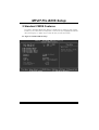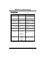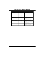
1
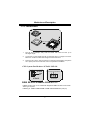
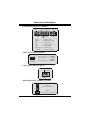
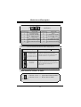
M o Prro TP VIIT M77V FCC Statement and Copyright This equipment has been tested and found to comply with the limits of a Class B digital dev ice, pursuant to Part 15 of the FCC Rules. These limits are designed to prov ide reasonable protection against harmful interference in a residential installation. This equipment generates, uses and can radiate radio frequency energy and, if not installed and used in accordance with the instructions, may cause harmf ul interference to radio communications. There is no guarantee that interf erence will not occur in a particular installation. The v endor makes no representations or warranties with respect to the contents here of and specially disclaims any implied warranties of merchantability or f itness f or any purpose. Further the vendor reserves the right to revise this publication and to make changes to the contents here of without obligation to notify any party bef orehand. Duplication of this publication, in part or in whole is not allowed without first obtaining the v endor’s approval in writing. The content of this user’s is subject to be changed without notice and we will not be responsible f or any mistakes f ound in this user’s manual. All the brand and product names are trademarks of their respective companies. i C Coonntteennttss ENGLISH .............................................................................................1 M7VIT Pro Features............................................................................1 Package contents...............................................................................2 Layout of M7VIT Pro...........................................................................3 CPU Installation.................................................................................4 DDR DIMM Modules: DIMM1-2-3...........................................................4 Jumpers, Headers, Connectors & Slots.................................................6 ESPAÑOL .......................................................................................... 11 Características del M7VIT Pro............................................................ 11 Contenido del Paquete..................................................................... 12 Disposición del M7VIT Pro ................................................................ 13 Instalación de la CPU........................................................................ 14 Módulos DDR DIMM: DIMM1-2-3......................................................... 15 Puentes, Cabezales, Conectores y Ranuras ........................................ 17 FRANÇAIS .........................................................................................22 M7VIT Pro Particularités: .................................................................. 22 Dessin d’M7VIT Pro.......................................................................... 24 WARPSPEEDER ................................................................................25 Introduction ................................................................................................................................... 25 S ystem Requirement ................................................................................................................... 25 Installation ...................................................................................................................................... 26 Usage............................................................................................................................................... 27 TROU BLE SHOOTING .......................................................................33 SOLUCIÓN DE PROBLEMAS.............................................................34 ii M Deessccrriippttiioonn MootthheerrbbooaarrddD English M7VIT Pro Features CPU Single AMD Socket-A for AMD Athlon/Duron Family processor. Running at 200/266/333 MHz Front Side Bus. Chipset North Bridge: VIA KT400/A. South Bridge: VT8235. Main - Memory Supports up to 3 DDR devices. Supports 200/266/333/400MHz (without ECC) DDR SDRAM devices. The largest memory capacity is up to 3GB. Slots Fiv e 32-bit PCI bus master slots. One CNR slot. One AGP slot. On Board IDE Supports four IDE disk drives. Supports PIO Mode 4, Master Mode and Ultra DMA 33/66/100/133 Bus Master Mode. LAN Chip VT6103 Dual Speed - 100/10 Mbps. Audio AC97 2.2 interface. PC99 complaint Supports 6 channels. On Board Peripherals Supports 360K, 720K, 1.2MB, 1.44MB and 2.88MB f loppy disk driv ers. Supports 2 serial ports. Supports 1 parallel port.(SPP/EPP/ECP mode) Supports PS/2 mouse and PS/2 key board. Supports 2 back USB2.0 ports and 4 front USB2.0 ports. BIOS AWARD legal Bios. Supports APM1.2. Supports ACPI. 1 M Deessccrriippttiioonn MootthheerrbbooaarrddD - Supports USB Function. Operating System Offers the highest performance f or MS-DOS, Windows 2000, Windows Me, Windows XP, SCO UNIX etc. Dimensions ATX Form Factor: 30.5cm X 20.0cm (W X L) - Package contents - HDD Cable X 1 FDD Cable X 1 Fully Setup Driv er CD X 1 Flash Memory Writer f or BIOS update X 1 USB Cable X 2 (Optional) Rear I/O Panel f or ATX Case X 1 (Optional) 2 M Deessccrriippttiioonn MootthheerrbbooaarrddD Layout of M7VIT Pro 1 1 J KBV1 Soc ket A J USBV 1 CPU 1 KT400 GAME Port MIC- IN LI NE- IN S P-OUT J AT XP WR1 12 JGAME1 JA UDIO1 IDE 1ID E2 13 14 AGP SLOT L AN C h ip 1 BAT1 PCI1 P CI S LOT 1 1 PCI2 P CI S LOT 4 6 1 3 J USB2 Code c 1 PCI3 P CI S LOT 2 10 1 9 VT8 235 J USB3 2 P CI4 Wi nb on d I /O J CMOS1 PCI SLOT 1 1 10 9 J USBV2 FDD1 PCI5 P CI S LOT BI OS C NR SLOT J WOL 1 1 1 CN R1 JSFA N1 3 JPANE L1 2 1 24 23 M Deessccrriippttiioonn MootthheerrbbooaarrddD CPU Installation CP U 1. Pull the lev er sideways away f rom the socket then raise the lever up to 90-degree angle. 2. Locate Pin A in the socket and lock f or the white dot or cut edge in the CPU. Match Pin A with the white dot/cut edge then insert the CPU. 3. Press the lev er down. Then Put the f an on the CPU and buckle it and put the f an’s power port into the JCFAN1, then to complete the installation. CPU/ S ystem Fan Headers: JCFAN1/ JS FAN1 1 12V S ense G round Ground 12V Se nse 1 JCFAN1 JSFAN1 DDR DIMM Modules: DIMM1-2-3 DRAM Access Time: 2.5V Unbuffered/ Registered DDR PC1600/ 2100/ 2700/ 3200 Ty pe required. DRAM Ty pe: 64MB/ 128MB/ 256MB/ 512MB/ 1GB DIMM Module (184 pin) 4 M Deessccrriippttiioonn MootthheerrbbooaarrddD DIMM Socket Location DDR Module To tal Memory Size (MB) DIMM 1 64MB/128MB/256MB/512MB/1GB *1 DIMM 2 64MB/128MB/256MB/512MB/1GB *1 Max is 3GB 64MB/128MB/256MB/512MB/1GB *1 ⌦The list shown abov e f or DRAM configuration is only f or ref erence. DIMM3 List of the status of DDR 400 already passed Clock Vender Serial No. (Chip) Module MEMTEST Size 1 DDR400 KINGMAX KDL684T4AA-50 Double Size 256M x2 Pass 2 DDR400 SAMSUNG K4H560838D-TCC4 Pass 3 DDR400 TwinMO S TMD7608F8E50B Single Size 256M x3 Single Size 256M x3 4 DDR400 Winbond W942508BH-5 Single Size 256M x3 Pass 5 DDR400 Winbond W942508BH-5 Pass Double Pass Size 512M x3 ⌦If use FSB 333MHz CPU, the DDR DIMM only support PC2700 DDR. How to install a DIMM Module 1. The DIMM socket has a “ Plastic Safety Tab”, and the DIMM memory module has an “Asymmetrical notch”, so the DIMM memory module can only f it into the slot in one direction. 2. Push the tabs out. Insert the DIMM memory modules into the socket at a 90-degree angle, then push down vertically so that it will fit into the place. 3. The Mounting Holes and plastic tabs should f ti over the edge and hold the DIMM 5 M Deessccrriippttiioonn MootthheerrbbooaarrddD memory modules in place. Jumpers, Headers, Connectors & Slots Hard Disk Connectors: IDE1/ IDE2 The motherboard has a 32-bit Enhanced PCI IDE Controller that provides PIO Mode 0~4, Bus Master, and Ultra DMA 33/ 66/ 100/ 133 functionality. It has two HDD connectors IDE1 (primary), IDE2 (secondary) and IDE3. The IDE connectors can connect a master and a slave driv e, so you can connect up to f our hard disk driv es. The f irst hard drive should alway s be connected to IDE1. Floppy Disk Connector: FDD1 The motherboard provides a standard f loppy disk connector that supports 360K, 720K, 1.2M, 1.44M and 2.88M floppy disk types. This connector supports the prov ided f loppy drive ribbon cables. Accelerated Graphics Port S lot: AGP1 (8X) Y our monitor will attach directly to that v ideo card. This motherboard supports video cards for PCI slots, but it is also equipped with an Accelerated Graphics Port (AGP). An AGP card will take advantage of AGP technology f or improved video efficiency and performance, especially with 3D graphics. Communication Network Riser S lot: CNR1 The CNR specification is an open Industry Standard Architecture, and it defines a hardware scalable riser card interface, which supports audio, network and modem only. Peripheral Component Interconnect Slots: PCI1-5 This motherboard is equipped with 5 standard PCI slots. PCI stands f or Peripheral Component Interconnect, and it is a bus standard f or expansion cards, which has, supplanted the older ISA bus standard in most ports. This PCI slot is designated as 32 bits. 6 M Deessccrriippttiioonn MootthheerrbbooaarrddD Power Connectors: JATXPWR1 JATX PWR1 JATXPWR1 (ATX M ain Po wer Con n.) (ATX Po wer Con n.) Wake On LAN Header: JWOL1 Ground Wake u p 5 V_SB 1 WOL1 Front USB Header: JUSB2/3 2 1 JUSB2/ 3 Pin Assignment 1 +5V 3 Data (-) 5 Data (+) 7 Ground 9 Key Pin Assignment 2 +5V 4 Data (-) 6 Data (+) 8 Ground 10 NA 5V/ 5 VS B Selection for US B/KB: JUSBV1/2/ JKBV1 JUSBV1/2 JKBV1 1 1 Pin 1-2 on ==> 5V (For Normal Function) Pin 2-3 on ==> 5V_SB (For S3 Wake-up Function) 7 M Deessccrriippttiioonn MootthheerrbbooaarrddD Front Panel Connector: JPANEL1 PWR_L ED (+) (+) (-) ON/OFF SLP IR 24 2 1 23 SPK (+) (-) HLE D RST IR SPK ==> Speaker Conn. HLED ==> Hard Driver LED RST ==> Reset Button IR ==> Infrared Conn. SLP ==> Sleep Button PWR_LED ==> Power LED ON/ OFF ==> Power-on Button CPU Clock S election: JCLK1 4 6 1 3 Pin 1-2, 5-6 ==> 100 Mhz Pin 2-3, 5-6 ==> 133 Mhz (default) Pin 2-3, 4-5 ==> 166Mhz JCLK1 Case Open Connector: JCI1 Ca se Ope n S ignal Gr ound 1 J CI1 Audio S ubsystem: JAUDIO1/ JCDIN1 1 2 J AUDI O1 (Fron t Au di o Header) 13 1 14 J CDIN1 (CD -ROM Au di o-In H eader) 8 M Deessccrriippttiioonn MootthheerrbbooaarrddD 22 1 Pin 1 3 5 7 9 11 13 14 13 Assignment Mic In Mic Power RT Line Out Reserved LFT Line Out RT Line In LFT Line In JA UDIO1 Assignment Ground Audio Power RT Line Out NC LFT Line Out RT Line In LFT Line In Pin 2 4 6 8 10 12 14 Front Panel Audio Connector/ Jumper Bloc k J umpe r Setting 1 3 5 7 9 11 13 2 4 6 1 3 5 7 9 11 13 2 4 6 10 12 14 10 12 14 C onfiguration Pin 5 and 6 Pin 9 and 1 0 Pin 11 an d 12 Pin 13 an d 14 Au dio lin e o ut sign als are ro uted to th e back p an el au dio lin e o ut con nector. No jum pers installed Au dio lin e o ut and m ic in s ig nals are ava ilable f or fro nt p anel au d io co nn ecto rs . Digital Audio Connector: JS PDIF1 JSPDIF1 1 Pin 1 2 3 9 Assign ment VC C5 SPDIF_ OUT GND M Deessccrriippttiioonn MootthheerrbbooaarrddD Clear CMOS Jumper: JCMOS1 1 JCMOS1 Pin 1-2 on ==> Normal Operation (default) Pin 2-3 on ==> Clear CMOS Data Back Panel Connectors JKBMS1 JUSBLAN 1 JPRNT1 PS/2 LAN(Optional) Mouse PS/2 Keyboard USB JGAME1 Parallel COM1 JCOM1 Game Port COM2 JCOM2 10 Speaker Out Line In Mic In M Deessccrriippttiioonn MootthheerrbbooaarrddD Español Características del M7VIT Pro Usa Chipsets North Bridge: VIA KT400, South Bridge: VT8235, Winbond W83697HF y Lan Chip- VT6103. Contiene facilidades I/O integrados en la placa madre en el que incluye dos puertos en serie, un puerto paralelo, un puertos de ratón PS/2, un puerto de teclado PS/2, puertos de audio, puertos USB y un puerto de juego. Soporta Single Socket-A para procesadores de la f amilia AMD Athlon/ Duron, corriendo a 200/266/333 MHz frecuencia Front Side Bus. El sistema bus AMD Athlon/ Duron soporta una alta v elocidad de 200/266/333 MHz, split-transaction AMD Athlon/ Duron sistemas de interface bus. Soporta Ultra DMA 33/66/100/133 Bus Modos Master, PIO Modo 4, Modo Master, y alta perf ormancia del disco duro. Soporta USB2.0 6 puertos Dispositivo High Speed, 2 puertos en el panel trasero y 4 puertos en el panel f rontal. El sistema controlador KT400 está diseñado para soportar 200/266/333/400 MHz DDR SDRAM DIMMs. Soporta tamaño de memoria máxima de hasta 3GB. Soporta una ranura CNR (solamente de Tipo B), una ranura AGP 4X, y cinco ranuras 32-bit PCI Bus. Conforma con las especif icaciones del f actor de forma de tamaño PC ATX. Soporta sistemas operativos populares tales como Windows NT, Windows 98SE, Windows 2000, Windows ME, Windows XP y LINUX. Protección contra el exceso de temperatura de la CPU. Intel® AC’97 2.2 compatible. High S/N ratio reune los requisitos del PC 99. Entrada de Línea y Entrada del Mic compartido con el Audio trasero con un total de 6 canales de Audio. 6 Canales AC97 Codec. (Cambiando la Entrada de Línea por la Salida del Audio Trasero y la Entrada del MIC por la salida Bass/ Center a trav és de la utilidad del audio.) Soporta f unciones del cabezal de Audio Frontal. Soporta f unciones SPDIF-Out Lan Chip- VT6103- Fast EtherNet 10/ 100 1-Puerto PHY/ Transceiver (Opcional): 11 M Deessccrriippttiioonn MootthheerrbbooaarrddD * Doble velocidad- 100/ 10Mbps. * Half and Full Duplex. * MII Interf ace al Controlador Ethernet. * Auto Negociación: 10/ 100, Full/ Half Duplex. * Conf orma con todas las aplicaciones IEEE 802.3, 10 Base-T y 100 Base-Tx Estándar. * Baseline Wander Correction. Contenido del Paquete Cable HDD X 1 Cable FDD X 1 Configuración completa del Driver CD X 1 Flash Memory Writer para actualización del BIOS X 1 Cable USB X 2 (Opcional) Panel Trasero I/O para Caja ATX X 1 (Opcional) 12 M Deessccrriippttiioonn MootthheerrbbooaarrddD Disposición del M7VIT Pro 1 1 JKBV1 Socke t A JU SBV1 CPU KT400 JAT XPW R1 Pue rto de Juego E ntrada E ntrada S ali da del del MIC de Li nea Altavoz 1 1 2 JGAME 1 JAUD IO1 IDE 1ID E2 13 14 LAN Ch i p 1 BAT1 PCI1 1 1 PCI2 4 6 1 3 JCMOS1 JUS B2 Code c 1 PCI3 2 10 1 9 VT823 5 JUS B3 2 PCI4 Win bo nd I /O 1 1 10 9 JU SBV2 PCI5 BI OS FDD1 JW OL1 1 1 CNR1 J SFAN1 13 JPANE L 1 2 1 24 23 M Deessccrriippttiioonn MootthheerrbbooaarrddD Instalación de la CPU CP U 1. Tire de la palanca del lado del zócalo, luego levante la palanca hasta un ángulo de 90 grados. 2. Sitúe el contacto A del zócalo y busque el punto blanco o corte el borde en la CPU. Empareje el contacto A con el punto blanco/ corte del borde, luego inserte la CPU. 3. Presione la palanca para abajo. Ponga el v entilador en la CPU y abróchelo. Luego ponga el puerto de corriente del ventilador en el JCFAN1. Y ya habrá completado su instalación. CPU/ Cabezales del Sistema de Ventilación: JCFAN1/ JS FAN1 1 12V Se nse Tier ra Tierra 12V Sen se 1 JCFAN1 JSFAN 1 14 M Deessccrriippttiioonn MootthheerrbbooaarrddD Módulos DDR DIMM: DIMM1-2-3 DRAM Tiempo de Acceso: 2.5V Unbuffered/ Registered DDR PC1600/ 2100/ 2700/ 3200 Tipo requerido. DRAM Tipo: 64MB/ 128MB/ 256MB/ 512MB/ 1GB Módulo DIMM. (184 contactos) Localización del Módulo DIMM Módulo DDR To tal del Tamaño de Memoria (MB) DIMM 1 64MB/128MB/256MB/512MB/1GB *1 DIMM 2 64MB/128MB/256MB/512MB/1GB *1 Máximo de 3GB 64MB/128MB/256MB/512MB/1GB *1 La lista de arriba para la configuración DRAM es solamente para referencia. DIMM3 Listado del estado del DDR400 Reloj Vendedor Número de Serie (Chip) Tamaño MEMTEST del Módulo 1 DDR400 KINGMAX KDL684T4AA-50 Doble Cara 256M x2 Pass 2 DDR400 SAMSUNG K4H560838D-TCC4 Una Cara 256M x3 Pass 3 DDR400 TwinMO S TMD7608F8E50B Una Cara 256M x3 Pass 4 DDR400 Winbond W942508BH-5 Una Cara 256M x3 Pass 5 DDR400 Winbond W942508BH-5 Doble Cara 512M x3 Pass Si usa FSB 333MHz CPU, DDR D IMM solamente soporta PC2700 DDR. 15 M Deessccrriippttiioonn MootthheerrbbooaarrddD Cómo instalar un Módulo DIMM 1. El zócalo DIMM tiene una lengüeta plástica de seguridad y el módulo de memoria DIMM tiene una muesca asimétrica, así el módulo de memoria DIMM puede caber solamente en la ranura de una sóla dirección. 2. Tire la lengüeta hacia afuera. Inserte los módulos de memoria DIMM en el zócalo a los 90 grados, luego empuje hacia abajo verticalmente de modo que encaje en el lugar. 3. Los agujeros de montaje y las lengüetas plásticas deben caber por sobre el borde y sostenga los módulos de memoria DIMM en el lugar. 16 M Deessccrriippttiioonn MootthheerrbbooaarrddD Puentes, Cabezales, Conectores y Ranuras Conectores del Disco Duro: IDE1/ IDE2 La placa madre tiene un controlador de 32-bit PCI IDE que proporciona Modo PIO 0~4, Bus Master, y funcionalidad Ultra DMA / 33/ 66/ 100. Tiene dos conectores HDD IDE1 (primario) y IDE2 (secundario). El conector IDE puede conectar a un master y un drive esclav o, así puede conectar hasta cuatro discos rígidos. El primer disco duro debe estar siempre conectado al IDE1. Conector para Disquete: FDD1 La placa madre proporciona un conector estándar del disquete (FDC) que soporta 360K, 720K, 1.2M, 1.44M y 2.88M tipos de disquete. Éste conector utiliza los cables de cinta proporcionados por el disquete. Ranura del Puerto Acelerado para Gráficos: AGP1 (8X) Su monitor se fijará directamente a la tarjeta de v ideo. Ésta placa madre soporta tarjetas de v ideo para ranuras PCI, y también está equipado con un Puerto Acelerado para Gráficos. Ésta tarjeta AGP tomará ventaja de la tecnología del AGP para el mejoramiento de la eficiencia y funcionamiento del v ideo, especialmente con gráficos 3D. Ranura de la Banda de Suspensión de Comunicación y Red: CNR1 La especificación CNR es una abierta Industria de Arquitectura Estándar, que def ine una tarjeta de interf ace escalable del hardware en el que soporta audio y modem. Ranura de Interconexión del Componente Periférico: PCI1-5 Ésta placa madre está equipada con 5 ranuras estándar PCI. PCI es la sigla para Interconexión del Componente Perif érico, y es un bus estándar para tarjetas de expansión en el que suplanta a la antigua bus estándar ISA, en su mayoría de las partes. Ésta ranura PCI está diseñado con 32 bits. Conector de Corriente: JATXPWR1 JATXPWR 1 (Conecto r de Co rriente AT X) 17 M Deessccrriippttiioonn MootthheerrbbooaarrddD Cabezal Wake On LAN: J WOL1 Ti erra Wake up 5V _SB 1 WOL1 Cabezal Frontal US B: JUS B2/ JUS B3 2 JUSB2/ 3 1 Contactos Asignacion 1 +5V 3 Data (-) 5 Data (+) 7 Tierra 9 Key Contactos 2 4 6 8 10 Asignacion +5V Data (-) Data (+) Ground NA 5V/ 5 VS B Selección para US B/KB: JUS BV1/2/ JKBV1 JUSBV1/2 JKBV1 1 1 Contacto 1-2 on ==> 5V (Para Funcion Normal) Contacto 2-3 on ==> 5V_SB (Para Funcion S3 Wake-up) Conector Case Open: JCI1 ~ al Cas e Op en Sen Tierra 1 JCI1 18 M Deessccrriippttiioonn MootthheerrbbooaarrddD Conector del Panel Frontal: JPANEL1 PWR_LED SLP ( +) ( +) ( -) ON/OFF IR 2 24 1 23 ( +) ( -) SPK HLED RS T IR SPK ==> Conector de Altavoz HLED ==> LED del Disco Duro RST ==> Boton de Reinicio IR ==> Conector Infrarojo SLP ==> Boton de Suspension PWR_LED ==> Corriente LED ON/ OFF ==> Boton de Encendido Selección del Reloj del CPU: JCLK1 4 6 1 3 Contacto 1-2, 5-6 ==> 100 Mhz Contacto 2-3, 5-6 ==> 133 Mhz (default) Contacto 2-3, 4-5 ==> 166Mhz JCLK1 Subsistema de Audio: JAUDIO1/ JCDIN1 1 2 13 14 1 JAUD IO1 (Cabez al F ronta l de Audio) JCDI N1 (Cabe zal de Ent rada de Audio CD-ROM) 19 M Deessccrriippttiioonn MootthheerrbbooaarrddD 22 1 14 13 JAUDIO1 Asignacion Asignacion Contactos Entrada del MIC Tierra 2 Corriente de Audio Corriente del MIC 4 RT Salida de Linea RT Salida de Linea 6 Key Reservado 8 LFT Salida de Linea LFT Salida de Linea 10 12 RT Entrada de Linea RT Entrada de Linea LFT Entrada de Linea LFT Entrada de Linea 14 Contactos 1 3 5 7 9 11 13 C onector del Pane l Frontal de Audio/ Jumper Block J umpe r Setting 1 3 5 7 9 11 13 2 4 6 1 3 5 7 9 11 13 2 4 6 C onfiguracion Co ntacto 5 & 6 La se ~nal d e s alid a d e linea del Au dio Co ntacto 9 & 1 0 enc amina al co nector d e la s alid a d e linea 10 Co ntacto 11 & 1 2 del Au dio ub icad o en el p anel tras ero . 12 Co ntacto 13 & 14 14 10 12 14 No jumpers installed La se ~nal d e s alid a d e linea del Au dio y la ~ d el en trad a d el mic es ta n disp on ib les s enal des de el co necto r d e A udio d el pan el fro ntal. Puente de Borrar CMOS : JCMOS1 1 Contacto 1-2 on ==> Operacion Normal (default) Contacto 2-3 on ==> Borrar Datos CMOS JCMOS1 20 M Deessccrriippttiioonn MootthheerrbbooaarrddD Conector Digital de Audio: JSPDIF1 Conta ct os Asi gna cion 1 VCC5 2 SP DIF _OUT GN D 3 JSP DIF1 1 Conectores del Panel Trasero JKBMS1 JUSBLAN1 Raton PS/2 Teclado PS/2 LAN(Opcional) USB JPRNT1 JGAME1 Paralelo Puerto de Juego COM1 COM2 JCOM1 JCOM2 21 Salida del Entrada Entrada de Altavoz de Linea Mic M Deessccrriippttiioonn MootthheerrbbooaarrddD Français M7VIT Pro Particularités: CPU Douille-A AMD Simple pour AMD processeur de Famille. Dirigeant à Autobus de Côté de Front de MHz 200/266/333. Chipset Pont du Nord : VIA. Pont du Sud : VT8235. Mémoire Principale Soutient dispositifs jusqu'à 3 DDR. Soutient dispositifs de DDR SDRAM de 200/266/333/400MHz (sans CEE). La plus grande capacité de mémoire(souvenir) est jusqu'à 3GB. Fentes Cinq f entes de maître d'autobus PCI 32 bits. Une f ente CNR. Une fente AGP. À bord IDE Soutient quatre IDE des lecteurs de disques. Soutient PIO Mode 4, le Mode de Maître et DMA Ultra 33/66/100/133 le Mode de Maître d'Autobus. Chip de réseau local VT6103 Vitesse Duelle 100/10 Mbps. Audio AC97 2.2 interface. PC99 la plainte. Soutient 6 canaux. À bord Périphériques Soutient 360Ko, 720Ko, 1.2MB, 1.44MB et 2.88MB des conducteurs de disquette. Soutient 2 ports périodiques. Soutient 1 port parallèle. (SPP/EPP/ECP mode) Soutient le souris de PS/2 et le clav ier de PS/2. Soutient 2 ports en arrière USB2.0 et 4 ports USB2.0. B IOS ACCORDENT le BIOS légal. 22 M Deessccrriippttiioonn MootthheerrbbooaarrddD - Soutient APM1.2. Soutient ACPI. Soutient la Fonction d'USB. Système de Fonctionnement Offre 'lexécution(perf ormance) la plus haute pour MS-DOS, Windows 2000, des Fenêtres Moi, Windows XP, SCO UNIX etc. Dimensions ATX Forment le Facteur : 30.5cm X 20.0cm (W X L) 23 M Deessccrriippttiioonn MootthheerrbbooaarrddD Dessin d’M7VIT Pro 1 1 J KBV1 Soc ket A J USBV 1 CPU 1 KT400 GAME Port MIC-IN L INE -IN SP -OUT J AT XP WR1 12 JGAME1 JA UDIO1 IDE 1ID E2 13 14 AGP SLOT L AN C h ip 1 BAT1 PCI1 P CI S LOT 1 1 PCI2 P CI S LOT 4 6 1 3 J USB2 Code c 1 PCI3 P CI S LOT 2 10 1 9 VT8 235 J USB3 2 P CI4 Wi nb on d I /O J CMOS1 PCI SLOT 1 1 10 9 J USBV2 PCI5 P CI S LOT BI OS C NR SLOT FDD1 J WOL 1 1 1 CN R1 JSFA N1 24 JPANE L1 2 1 24 23 M Deessccrriippttiioonn MootthheerrbbooaarrddD WarpSpeeder Introduction [ WarpSpeeder™ ], a new powerf ul control utility, f eatures three user-f riendly functions including Ov erclock Manager, Ov ervoltage Manager, and Hardware Monitor. The f ollowing three sections detail the installation of FastTrak 376 drivers on a system that has Windows 98/Me already installed. If you’re installing the FastTrak 376 driv ers on a system during a Windows 98/Me installation, see “Installing Driv ers During Windows 98/Me Installation” on page 10. With the Overclock Manager, users can easily adjust the frequency they prefer or they can get the best CPU performance with just one click. The Ov ervoltage Manager, on the other hand, helps to power up CPU core v oltage and Memory voltage. The cool Hardware Monitor smartly indicates the temperatures, voltage and CPU fan speed as well as the chipset information. Also, in the About panel, you can get detail descriptions about BIOS model and chipsets. In addition, the f requency status of CPU, memory, AGP and PCI along with the CPU speed are sy nchronically shown on our main panel. Moreov er, to protect users' computer systems if the setting is not appropriate when testing and results in system f ail or hang, [ WarpSpeeder™ ] technology assures the sy stem stability by automatically rebooting the computer and then restart to a speed that is either the original system speed or a suitable one. System Requirement OS Support: Windows 98 SE, Windows Me, Windows 2000, Windows XP DirectX: DirectX 8.1 or abov e. (The Windows XP operating system includes DirectX 8.1. If you use Windows XP, you do not need to install DirectX 8.1.) 25 M Deessccrriippttiioonn MootthheerrbbooaarrddD Installation 1. Execute the setup execution f ile, and then the following dialog will pop up. Please click “Next” button and f ollow the default procedure to install. 2. When y ou see the f ollowing dialog in setup procedure, it means setup is completed. If the “Launch the WarpSpeeder Tray Utility” checkbox is checked, the Tray Icon utility and [ WarpSpeeder™ ] utility will be automatically and immediately launched after y ou click “Finish” button. 26 M Deessccrriippttiioonn MootthheerrbbooaarrddD Usage The following figures are just only for reference, the screen printed in this user manual will change according to your motherboard on hand. [ WarpSpeeder™ ] includes 1 tray icon and 5 panels: 1. Tray Icon: Whenev er the Tray Icon utility is launched, it will display a little tray icon on the right side of Windows Taskbar. This utility is responsible for conv eniently invoking [ WarpSpeeder™ ] Utility. Y ou can use the mouse by clicking the left button in order to invoke [ WarpSpeeder™ ] directly from the little tray icon or you can right-click the little tray icon to pop up a popup menu as f ollowing figure. The “Launch Utility” item in the popup menu has the same f unction as mouse left-click on tray icon and “Exit” item will close Tray Icon utility if selected. 2. Main Panel If you click the tray icon, [ WarpSpeeder™ ] utility will be invoked. Please ref er do the f ollowing figure; the utility ’s first window y ou will see is Main Panel. Main Panel contains features as follows: a. Display the CPU Speed, CPU external clock, Memory clock, AGP clock, and PCI 27 M Deessccrriippttiioonn MootthheerrbbooaarrddD clock inf ormation. b. Contains About, Voltage, Overclock, and Hardware Monitor Buttons f or invoking respective panels. c. With a user-friendly Status Animation, it can represent 3 ov erclock percentage stages: Man walking => ov erclock percentage from 100% ~ 110 % Panther running => overclock percentage from 110% ~ 120% Car racing => ov erclock percentage f rom 120% ~ above 28 M Deessccrriippttiioonn MootthheerrbbooaarrddD 3. Voltage Panel Click the Voltage button in Main Panel, the button will be highlighted and the Voltage Panel will slide out to up as the f ollowing figure. In this panel, you can decide to increase CPU core voltage and Memory voltage or not. The def ault setting is “No”. If y ou want to get the best performance of ov erclocking, we recommend y ou click the option “Y es”. 4. Overclock Panel Click the Ov erclock button in Main Panel, the button will be highlighted and the Overclock Panel will slide out to left as the f ollowing figure. 29 M Deessccrriippttiioonn MootthheerrbbooaarrddD Overclock Panel contains the these features: a. “–3MHz button”, “-1MHz button”, “+1MHz button”, and “+3MHz button”: prov ide user the ability to do real-time overclock adjustment. b. Warning:Manually overclock is potentially dangerous, especially when the overclocking percentage is over 110 %. We strongly recommend you verify every speed you overclock by click the Verify button. Or, you can just click Auto overclock button and let [ WarpSpeeder™ ] automatically gets the best result for you. b. “Recovery Dialog button”: Pop up the following dialog. Let user select a restoring way if system need to do a f ail-safe reboot. c. “Auto-ov erclock button”: User can click this button and [ WarpSpeeder™ ] will set the best and stable performance and frequency automatically. [ WarpSpeeder™ ] utility will execute a series of testing until system f ail. Then system will do f ail-saf e reboot by using Watchdog f unction. After reboot, the [ WarpSpeeder™ ] utility will restore to the hardware def ault setting or load the verif ied best and stable frequency according to the Recovery Dialog’s setting. d. “Verify button”: User can click this button and [ WarpSpeeder™ ] will proceed a testing f or current frequency. If the testing is ok, then the current f requency will be sav ed into system registry. If the testing f ail, system will do a fail-safe rebooting. After reboot, the [ WarpSpeeder™ ] utility will restore to the hardware default setting or load the verif ied best and stable frequency according to the Recovery Dialog’s setting. 30 M Deessccrriippttiioonn MootthheerrbbooaarrddD Note: Because the testing programs, invoked in Auto-overclock and Verify, include DirectDraw, Direct3D and DirectShow tests, the DirectX 8.1 or newer runtime library is required. And please make sure your display card’s color depth is High color (16 bit) or True color( 24/32 bit ) that is required for Direct3D rendering. 5. Hardware Monitor Panel Click the Hardware Monitor button in Main Panel, the button will be highlighted and the Hardware Monitor panel will slide out to left as the f ollowing figure. In this panel, you can get the real-time status information of y our system. The information will be ref reshed ev ery 1 second. 31 M Deessccrriippttiioonn MootthheerrbbooaarrddD 6. About Panel Click the About button in Main Panel, the button will be highlighted and the About Panel will slide out to up as the following f igure. In this panel, you can get model name and detail inf ormation in hints of all the chipset that are related to overclocking. Y ou can also get the mainboard’s BIOS model and the Version number of [ WarpSpeeder™ ] utility. Note: Because the overclock, overvoltage, and hardware monitor features are controlled by several separate chipset, [ WarpSpeeder™ ] divide these features to separate panels. If one chipset is not on board, the correlative button in Main panel will be disabled, but will not interfere other panels’ functions. This property can make [ WarpSpeeder™ ] utility more robust. 32 M Deessccrriippttiioonn MootthheerrbbooaarrddD Trouble Shooting PROBABLE SOLUTION No power to the system at all Power light don’t * Make sure power cable is securely plugged in illuminate, fan inside power supply does not turn * Replace cable on. Indicator light on keyboard does not turn on * Contact technical support PROBABLE SOLUTION System inoperative. Keyboard lights are on, * Using even pressure on both ends of the power indicator il ghts are lit, hard drive is DIMM, press down firmly until the module snaps into place. spinning. PROBABLE SOLUTION System does not boot from hard disk drive, can * Check cable running from disk to disk be booted from CD-ROM drive. controller board. Make sure both ends are securely plugged in; check the drive type in the standard CMOS setup. * Backing up the hard drive is extremely important. All hard dis ks are capable o breaking down at any time. PROBABLE SOLUTION System only boots from CD-ROM. Hard disk can * Back up data and applications files. Reforma be read and applications can be used but the hard drive. Re-install applications and data using backup disks. booting from hard disk is impossible. PROBABLE SOLUTION Screen message says “Invalid Configuration” or * Review system’s equipment . Make sure “CMOS Failure.” correct information is in setup. PROBABLE SOLUTION Cannot boot system after installing second hard * Set master/slave jumpers correctly. drive. * Run SET UP program and select correct drive types. Call drive manufacturers for compatibility with other drives. 33 Solución de Problemas CAUSA PROB ABLE SOLUCIÓN No hay corriente en el sistema. La luz de * corriente no ilumina, ventilador dentro de la fuente de alimentación apagada. Indicador de * luz del teclado apagado. * Asegúrese que el cable de transmisión esté seguramente enchufado. Reemplace el cable. Contacte ayuda técnica. CAUSA PROBABLE SOLUCIÓN Sistema inoperativo. Luz del teclado encendido, * Presione los dos extremos del DIMM, presione luz de indicador de corriente iluminado, disco para abajo firmemente hasta que el módulo rígido está girando. encaje en el lugar. CAUSA PROBABLE SOLUCIÓN Sistema no arranca desde el disco rígido, puede * Controle el cable de ejecución desde el disco ser arrancado desde el CD-ROM drive. hasta el disco del controlador. Asegúrese de que ambos lados estén enchufados con seguridad; controle el tipo de disco en la configuración estándar CMOS. * Copiando el disco rígido es extremadamente importante. T odos los discos rígidos son capaces de dañarse en cualquier momento. CAUSA PROB ABLE SOLUCIÓN Sistema solamente arranca desde el CD-ROM. * Copie datos y documentos de aplicación Disco rígido puede leer y aplicaciones pueden Vuelva a formatear el disco rígido. Vuelva a ser usados pero el arranque desde el disco instalar las aplicaciones y datos usando e rígido es imposible. disco de copiado. CAUSA PROB ABLE SOLUCIÓN Mensaje de pantalla ”Invalid Configuration” o * Revise el equipo del sistema. Asegúrese de que la información configurada sea correcta. “CMOS Failure.” CAUSA PROB ABLE SOLUCIÓN No puede arrancar después de instalar el * Fije correctamente el puente master/esclavo. segundo disco rígido. * Ejecute el programa SET UP y seleccione e tipo de disco correcto. Llame a una manufacturación del disco para compatibilidad con otros discos. 34 27/02/2003 35 M7VIT Pro BIOS Setup BIOS Setup........................................................................................1 1 Main Menu..................................................................................................... 3 2 Standard CMOS Features .............................................................................. 6 3 Advanced BIOS Features............................................................................... 9 4 Advanced Chipset Features.......................................................................... 12 5 Integrated Peripherals .................................................................................. 16 6 Power Management Setup ........................................................................... 21 7 PnP/PCI Configurations ............................................................................... 25 8 PC Health Status .......................................................................................... 28 9 Frequency/ Voltage Control......................................................................... 30 i M7VIT Pro BIOS Setup BIOS Setup Introduction This manual discussed Award™ Setup program built into the ROM BIOS. The Setup program allows users to modify the basic system configuration. This special information is then stored in battery-backed RAM so that it retains the Setup information when the power is turned off. The Award BIOS™ installed in your computer system’s ROM (Read Only Memory) is a custom version of an industry standard BIOS. This means that it supports Intel Pentium ® 4 processor input/output system. The BIOS provides critical low-level support for standard devices such as disk drives and serial and parallel ports. Adding important has customized the Award BIOS™, but nonstandard, features such as virus and password protection as well as special support for detailed fine-tuning of the chipset controlling the entire system. The rest of this manual is intended to guide you through the process of configuring your system using Setup. Plug and Play Support These AWARD BIOS supports the Plug and Play Version 1.0A specification. ESCD (Extended System Configuration Data) write is supported. EPA Green PC Support This AWARD BIOS supports Version 1.03 of the EPA Green PC specification. APM Support These AWARD BIOS supports Version 1.1&1.2 of the Advanced Power Management (APM) specification. Power management features are implemented via the System Management Interrupt (SMI). Sleep and Suspend power management modes are supported. Power to the hard disk drives and video monitors can be managed by this AWARD BIOS. ACPI Support Award ACPI BIOS support Version 1.0 of Advanced Configuration and Power interface specification (ACPI). It provides ASL code for power management and device configuration capabilities as defined in the ACPI specification, developed by Microsoft, Intel and Toshiba. 1 M7VIT Pro BIOS Setup PCI Bus Support This AWARD BIOS also supports Version 2.1 of the Intel PCI (Peripheral Component Interconnect) local bus specification. DRAM Support DDR SDRAM (Double Data Rate Synchronous DRAM) are supported. Supported CPUs This AWARD BIOS supports the AMD CPU. Using Setup In general, you use the arrow keys to highlight items, press <Enter> to select, use the <PgUp> and <PgDn> keys to change entries, press <F1> for help and press <Esc> to quit. The following table provides more detail about how to navigate in the Setup program by using the keyboard. Keystroke Up arrow Down arrow Left arrow Right arrow Move Enter PgUp key PgDn key + Key - Key Esc key F1 key F5 key F6 key F7 key F10 key Function Move to previous item Move to next item Move to the item on the left (menu bar) Move to the item on the right (menu bar) Move to the item you desired Increase the numeric value or make changes Decrease the numeric value or make changes Increase the numeric value or make changes Decrease the numeric value or make changes Main Menu – Quit and not save changes into CMOS Status Page Setup Menu and Option Page Setup Menu – E xit Current page and return to Main Menu General help on Setup navigation keys Load previous values from CMOS Load the fail-safe defaults from B IOS default table Load the optimized defaults Save all the CMOS changes and exit 2 M7VIT Pro BIOS Setup 1 Main Menu Once you enter Award BIOS™ CMOS Setup Utility, the Main Menu will appear on the screen. The Main Menu allows you to select from several setup functions. Use the arrow keys to select among the items and press <Enter> to accept and enter the sub-menu. !! WARNING !! The information about BIOS defaults on manual (Figure 1,2,3,4,5,6,7,8,9) is just for reference, please refer to the BIOS installed on board, for update information. Figure 1. Main Menu Standard CMOS Features This submenu contains industry standard configurable options. Advanced BIOS Features This submenu allows you to configure enhanced features of the BIOS. Advanced Chipset Features This submenu allows you to configure special chipset features. 3 M7VIT Pro BIOS Setup Integrated Peripherals This submenu allows you to configure certain IDE hard drive options and Programmed Input/ Output features. Power Management Setup This submenu allows you to configure the power management features. PnP/PCI Configurations This submenu allows you to configure certain “Plug and Play” and PCI options. PC Health Status This submenu allows you to monitor the hardware of your system. Frequency/ Voltage Control This submenu allows you to change CPU Vcore Voltage and CPU/PCI clock. (However, this function is strongly recommended not to use. Not properly change the voltage and clock may cause CPU or M/B damage!) Load Optimized Defaults This selection allows you to reload the BIOS when the system is having problems particularly with the boot sequence. These configurations are factory settings optimized for this system. A confirmation message will be displayed before defaults are set. Set Supervisor Password Setting the supervisor password will prohibit everyone except the supervisor from making changes using the CMOS Setup Utility. You will be prompted with to enter a password. 4 M7VIT Pro BIOS Setup Set User Password If the Supervisor Password is not set, then the User Password will function in the same way as the Supervisor Password. If the Supervisor Password is set and the User Password is set, the “User” will only be able to view configurations but will not be able to change them. Save & Exit Setup Save all configuration changes to CMOS(memory) and exit setup. Confirmation message will be displayed before proceeding. Exit Without Saving Abandon all changes made during the current session and exit setup. message will be displayed before proceeding. Upgrade BIOS This submenu allows you to upgrade bios. 5 confirmation M7VIT Pro BIOS Setup 2 Standard CMOS Features The items in Standard CMOS Setup Menu are divided into 10 categories. Each category includes no, one or more than one setup items. Use the arrow keys to highlight the item and then use the<PgUp> or <PgDn> keys to select the value you want in each item. Figure 2. Standard CMOS Setup 6 M7VIT Pro BIOS Setup Main Menu Selections This table shows the selections that you can make on the Main Menu. Item Options Date mm : dd : yy Set the system date. Note that the ‘Day’ automatically changes when you set the date. Time hh : mm : ss Set the clock. IDE Primary Master Options are in its sub menu. Press <Enter> to enter the sub menu of detailed options IDE Primary Slave Options are in its sub menu. Press <Enter> to enter the sub menu of detailed options. IDE Secondary Master Options are in its sub menu. Press <Enter> to enter the sub menu of detailed options. IDE Secondary Slave Options are in its sub menu. Press <Enter> to enter the sub menu of detailed options. Drive A 360K, 5.25 in Drive B 1.2M, 5.25 in Select the type of floppy disk drive installed in your system. 720K, 3.5 in Description system internal 1.44M, 3.5 in 2.88M, 3.5 in None Video EGA/VGA CGA 40 CGA 80 MONO 7 Select the default device. video M7VIT Pro BIOS Setup Item Halt On Options Description All Errors Select the situation in which No Errors you want the BIOS to stop All, but Keyboard All, but Diskette the POST process and notify you. All, but Disk/ Key Base Memory N/A Displays the amount of conventional memory detected during boot up. Extended Memory N/A Displays the amount of extended memory detected during boot up. Total Memory N/A Displays the total memory available in the system. 8 M7VIT Pro BIOS Setup 3 Advanced BIOS Features Figure 3. Advanced BIOS Setup Boot Seq & Floppy Setup This item allows you to setup boot seq & Floppy. First/ Second/ Third/ Boot Other Device These BIOS attempt to load the operating system from the devices in the sequence selected in these items. The Choices: Floppy, LS120, HDD-0, SCSI, CDROM, HDD-1, HDD-2, HDD-3, ZIP100, LAN, Disabled. Swap Floppy Drive For systems with two floppy drives, this option allows you to swap logical drive assignments. The Choices: Disabled (default), Enabled. Boot Up Floppy Seek Enabling this option will test the floppy drives to determine if they have 40 or 80 tracks. Disabling this option reduces the time it takes to boot-up. The Choices: Enabled (default), Disabled. 9 M7VIT Pro BIOS Setup Cache & Shadow Setup This item allows you to setup cache & shadow setup. CPU Internal Cache Depending on the CPU/chipset in use, you may be able to increase memory access time with this option. Enabled (default) Enable cache. Disabled Disable cache. External Cache This option enables or disables “Level 2” secondary cache on the CPU, which may improve performance. Enabled (default) Enable cache. Disabled Disable cache. CPU L2 Cache ECC Checking This item allows you to enable/disable CPU L2 Cache ECC Checking. The Choices: Enabled (default), Disabled. Video BIOS Shadow Determines whether video BIOS will be copied to RAM for faster execution. Enabled (default) Optional ROM is enabled. Disabled Optional ROM is disabled. Virus Warning This option allows you to choose the Virus Warning feature that is used to protect the IDE Hard Disk boot sector. If this function is enabled and an attempt is made to write to the boot sector, BIOS will display a warning message on the screen and sound an alarm beep. Disabled (default) Virus protection is disabled. Enabled Virus protection is activated. Quick Power On Self Test Enabling this option will cause an abridged version of the Power On Self-Test (POST) to execute after you power up the computer. Enabled (default) Enable quick POST. Disabled Normal POST. Boot Up NumLock Status Selects the NumLock. State after power on. On (default) Numpad is number keys. Off Numpad is arrow keys. Gate A20 Option Select if chipset or keyboard controller should control Gate A20. Normal A pin in the keyboard controller 10 M7VIT Pro BIOS Setup Fast (default) controls Gate A20. Lets chipset control Gate A20. Typematic Rate Setting When a key is held down, the keystroke will repeat at a rate determined by the keyboard controller. When enabled, the typematic rate and typematic delay can be configured. Disabled (default) Enabled Typematic Rate (Chars/Sec) Sets the rate at which a keystroke is repeated when you hold the key down. The Choices: 6 (default), 8,10,12,15,20,24,30. Typematic Delay (Msec) Sets the delay time after the key is held down before it begins to repeat the keystroke. The Choices: 250 (default), 500,750,1000. Security Option This option will enable only individuals with passwords to bring the system online and/or to use the CMOS Setup Utility. System A password is required for the system to boot and is also required to access the Setup Utility. Setup (default) A password is required to access the Setup Utility only. This will only apply if passwords are set from the Setup main menu. MPS Version Control For OS The BIOS supports version 1.1 and 1.4 of the Intel multiprocessor specification. Select version supported by the operation system running on this computer. The Choices: 1.4 (default), 1.1. OS Select For DRAM > 64MB A choice other than Non-OS2 is only used for OS2 systems with memory exceeding 64MB. The Choices: Non-OS2 (default), OS2. Summary Screen Show This item allows you to enable/ disable display the Summary Screen Show. The Choices: Disabled (default), Enabled. 11 M7VIT Pro BIOS Setup 4 Advanced Chipset Features This submenu allows you to configure the specific features of the chipset installed on your system. This chipset manage bus speeds and access to system memory resources, such as DRAM. It also coordinates communications with the PCI bus. The default settings that came with your system have been optimized and therefore should not be changed unless you are suspicious that the settings have been changed incorrectly. Figure 4. Advanced Chipset Setup DRAM Clock/Drive Control To control the Clock/Drive. If you highlight the literal “Press Enter” next to the “DRAM Clock/Drive Control” label and then press the enter key, it will take you a submenu with the following options: DRAM Clock This item determines DRAM clock following 100MHz, 133MHz, 166MHz or By SPD. The Choices: 100MHz, 133MHz, By SPD (default), 166MHz. 12 M7VIT Pro BIOS Setup DRAM Timing This item determines DRAM clock/ timing follow SPD or not. The Choices: Auto By SPD (default), Manual, Turbo, Ultra. DRAM CAS Latency When DRAM is installed, the number of clock cycles of CAS latency depends on the DRAM timing. The Choices: 2.5 (default), 2. Bank Interleave This item allows you to enable or disable the bank interleave feature. The Choices: Disabled (default), 2 bank, 4 bank. Precharge to Active (Trp) This items allows you to specify the delay from precharge command to activate command. The Choices: 2T, 3T (default). Tras Non-DDR400/ DDR400 This items allows you to set Tras Non-DDR400/DDR400. The Choices: 7T/10T (default), 6T/8T, 5T/6T, 8T/12T. Active to CMD (Trcd) Use this item to specify the delay from the activation of a bank to the time that a read or write command is accepted. The Choices: 2T, 3T (default). DRAM Burst Length The Choices: 4 (default), 8. DRAM Queue Depth This item permits to place the depths of the memory. the better is this function. The Choices: 4 level (default), 2 level, 3 level. The deeper the depth is, DRAM Command Rate This item controls clock cycle that must occur between the last valid write operation and the next command. The Choices: 1T Command, 2T Command (default). Write Recovery Time The Choices: 3T (default), 2T. tWTR for DDR400 ONLY The Choices: 3T (default), 1T, 2T. 13 M7VIT Pro BIOS Setup AGP & P2P Bridge Control If you highlight the literal “Press Enter” next to the “AGP & P2P Bridge Control” label and then press the enter key, it will take you a submenu with the following options: AGP Aperture Size Select the size of the Accelerated Graphics Port (AGP) aperture. The aperture is a portion of the PCI memory address range dedicated for graphics memory address space. Host cycles that hit the aperture range are forwarded to the AGP without any translation. The Choices: 64M, 256M, 128M (default), 32M, 16M, 8M, 4M. AGP Mode This item allows you to select the AGP Mode. The Choices: 4X (default), 2X, 1X. AGP Driving Control By choosing “Auto” the system BIOS will the AGP output Buffer Drive strength P Ctrl by AGP Card. By choosing “Manual”, it allows user to set AGP output Buffer Drive strength P Ctrl by manual. The Choices: Auto (default), Manual. AGP Driving Value While AGP driving control item set to “Manual”, it allows user to set AGP driving. The Choices: DA (default). AGP Fast Write The Choices: Enabled, Disabled (default). AGP Master 1 WS Write When Enabled, writes to the AGP (Accelerated Graphics Port) are executed with one-wait states. The Choices: Disabled (default), Enabled. AGP Master 1 WS Read When Enabled, read to the AGP (Accelerated Graphics Port) are executed with one wait states. The Choices: Disabled (default), Enabled. AGP 3.0 Calibration cycle This item allows you to enable or disable AGP 3.0 Calibration cycle. The Choices: Enabled (Default), Disabled. 14 M7VIT Pro BIOS Setup CPU & PCI Bus Control If you highlight the literal “Press Enter” next to the “CPU & PCI Bus Control” label and then press the enter key, it will take you a submenu with the following options: PCI1 Master 0 WS Write When enabled, writes to the PCI bus are executed with zero-wait states. The Choices: Enabled (default), Disabled. PCI2 Master 0 WS Write When enabled, writes to the AGP bus are executed with zero-wait states. The Choices: Enabled (default), Disabled. PCI1 Post Write When Enabled, CPU writes are allowed to post on the PCI bus. The Choices: Enabled (default), Disabled. PCI2 Post Write When Enabled, CPU writes are allowed to post on the AGP bus. The Choices: Enabled (default), Disabled. VLink 8X Support The Choices: Enabled (default), Disabled. PCI Delay Transaction The chipset has an embedded 32-bit posted write buffer to support delay transactions cycles. Select Enabled to support compliance with PCI specification. The Choices: Enabled (default), Disabled. Memory Hole When enabled, you can reserve an area of system memory for ISA adapter ROM. When this area is reserved, it cannot be cached. Refer to the user documentation of the peripheral you are installing for more information. The Choices: Disabled (default), 15M – 16M. System BIOS Cacheable Selecting the “Enabled” option allows caching of the system BIOS ROM at F0000h-FFFFFh, which can improve system performance. However, any programs writing to this area of memory will cause conflicts and result in system errors. The Choices: Enabled, Disabled (default). Video RAM Cacheable Enabling this option allows caching of the video RAM, resulting in better system performance. However, if any program writes to this memory area, a system error may result. The Choices: Enabled, Disabled (default). 15 M7VIT Pro BIOS Setup 5 Integrated Peripherals Figure 5. Integrated Peripherals VIA OnChip IDE Device The chipset contains a PCI IDE interface with support for two IDE channels. Select “Enabled” to activate the first and / or second IDE interface. If you install a primary and / or secondary add-in IDE interface, select “Disabled” to deactivate an interface. If you highlight the literal “Press Enter” next to the “Onchip IDE Control” label and then press the enter key, it will take you a submenu with the following options: OnChip IDE Channel 0/1 The motherboard chipset contains a PCI IDE interface with support for two IDE channels. Select “Enabled” to activate the first and/or second IDE interface. Select “Disabled” to deactivate an interface if you are going to install a primary and/or secondary add-in IDE interface. The Choices: Enabled (default), Disabled. IDE Prefetch Mode The “onboard” IDE drive interfaces supports IDE prefetching for faster drive access. If the interface does not support prefetching. If you install a primary and/or secondary add-in IDE interface, set this option to “Disabled”. The Choices: Enabled (default), Disabled. 16 M7VIT Pro BIOS Setup IDE Primary / Secondary Master / Slave PIO The IDE PIO (Programmed Input / Output) fields let you set a PIO mode (0-4) for each of the IDE devices that the onboard IDE interface supports. Modes 0 through 4 provides successively increased performance. In Auto mode, the system automatically determines the best mode for each device. The Choices: Auto (default), Mode0, Mode1, Mode2, Mode3, Mode4. IDE Primary / Secondary Master / Slave UDMA Ultra DMA/100 functionality can be implemented if it is supported by the IDE hard drives in your system. As well, your operating environment requires a DMA driver (Windows 95 OSR2 or a third party IDE bus master driver). If your hard drive and your system software both support Ultra DMA/100, select Auto to enable BIOS support. The Choices: Auto (default), Disabled. VIA OnChip PCI Device If you highlight the literal “Press Enter” next to the “OnChip PCI Device” label and then press the enter key, it will take you a submenu with the following options: VIA-3058 AC97 Audio This option allows you to control the onboard AC97 audio. The Choices: Auto (default), Disabled. VIA-3068 MC97 Modem This option allows you to control the onboard MC97 modem. The Choices: Auto (default), Disabled. VIA-3043 OnChip LAN This option allows you to control the onboard LAN. The Choices: Enabled (default), Disabled. Onboard LAN Boot ROM This item allows you to enable or disable Onboard LAN Boot ROM. The Choices: Disabled (default), Enabled. Super IO Device If you highlight the literal “Press Enter” next to the “Super IO Device” label and then press the enter key, it will take you a submenu with the following options: Onboard FDC Controller Select Enabled if your system has a floppy disk controller (FDC) installed on the system board and you wish to use it. If install and FDC or the system has no floppy drive, select Disabled in this field. The Choices: Enabled (default), Disabled. 17 M7VIT Pro BIOS Setup Onboard Serial Port 1 Select an address and corresponding interrupt for the first and second serial ports. The Choices: Disabled, 3F8/IRQ4 (default), 2F8/IRQ3, 3E8/IRQ4, 2E8/IRQ3, Auto. Onboard Serial Port 2 Select an address and corresponding interrupt for the first and second serial ports. The Choices: Disabled, 2F8/IRQ3 (default), 3F8/IRQ4, 3E8/IRQ4, 2E8/IRQ3, Auto. UART Mode Select This item allows you to determine which Infra Red (IR) function of onboard I/O chip. The Choices: Normal (default), AS KIR, IrDA. RxD, TxD Active This item allows you to determine which Infrared (IR) function of onboard I/O chip. The Choices: Hi / Lo (default), Hi / Hi, Lo / Hi, Lo / Lo. IR Transmission Delay This item allows you to enable/disable IR transmission delay. The Choices: Enabled (default), Disabled. UR2 Duplex Mode Select the value required by the IR device connected to the IR port. Full-duplex mode permits simultaneous two-direction transmission. Half-duplex mode permits transmission in one direction only at a time. The Choices: Half (default), Full. Use IR Pins Consult your IR peripheral documentation to select the correct setting of the TxD and RxD signals. The Choices: IR-Rx2Tx2 (default), RxD2, TxD2. Onboard Parallel Port This item allows you to determine access onboard parallel port controller with which I/O Address. The Choices: 378/IRQ7 (default), 278/IRQ5, 3BC/IRQ7, Disabled. Parallel Port Mode The default value is SPP. The Choices: SPP(default) EPP ECP Using Parallel port as Standard Printer Port. Using Parallel Port as Enhanced Parallel Port. Using Parallel port as Extended Capabilities Port. 18 M7VIT Pro BIOS Setup ECP+EPP Using Parallel port as ECP & EPP mode. EPP Mode Select Select EPP port type 1.7 or 1.9. The Choices: EPP 1.7(default), EPP1.9. ECP Mode Use DMA Select a DMA Channel for the port. The Choices: 3 (default), 1. Game Port Address Game Port I/O Address. The Choices: 201 (default), 209, Disabled. Midi Port Address Midi Port Base I/O Address. The Choices: 330 (default), 300, 290, Disabled. Midi Port IRQ This determines the IRQ in which the Midi Port can use. The Choices: 5, 10 (default) Init Display First With systems that have multiple video cards, this option determines whether the primary display uses a PCI Slot or an AGP Slot. The Choices: PCI Slot (default), AGP. OnChip USB Controller This option should be enabled if your system has a USB installed on the system board. You will need to disable this feature if you add a higher performance controller. The Choices: All Enabled (default), All Disabled, 1&2 USB Port, 2&3 USB Port, 1&3 USB Port, 1 USB Port, 2 USB Port, 3 USB Port. USB Keyboard Support Enables support for USB attached keyboards. The Choices: Disabled (default), Enabled. USB Mouse Support Enables support for USB attached mouse. The Choices: Disabled (default), Enabled. IDE HDD Block Mode Block mode is also called block transfer, multiple commands, or multiple sector read / write. 19 M7VIT Pro BIOS Setup If your IDE hard drive supports block mode (most new drives do), select Enabled for automatic detection of the optimal number of block mode (most new drives do), select Enabled for automatic detection of the optimal number of block read / write per sector where the drive can support. The Choices: Enabled (default), Disabled. 20 M7VIT Pro BIOS Setup 6 Power Management Setup The Power Management Setup Menu allows you to configure your system to utilize energy conservation and power up/power down features. Figure 6. Power Management Setup ACPI function This item displays the status of the Advanced Configuration and Power Management (ACPI). The Choices: Enabled (default), Disabled. ACPI Suspend Type The item allows you to select the suspend type under the ACPI operating system. The Choices: S1 (POS) (default) Power on Suspend S3 (STR) Suspend to RAM S1+S3 POS+STR Power Management This category allows you to select the type (or degree) of power saving and is directly related to the following modes: 1.HDD Power Down. 2.Suspend Mode. 21 M7VIT Pro BIOS Setup There are four options of Power Management, three of which have fixed mode settings Min. Power Saving Minimum power management. Suspend Mode = 1 hr. HDD Power Down = 15 min Max. Power Saving Maximum power management only available for sl CPU’s. Suspend Mode = 1 min. HDD Power Down = 1 min. User Defined (default) Allows you to set each mode individually. When not disabled, each of the ranges are from 1 min. to 1 hr. except for HDD Power Down which ranges from 1 min. to 15 min. and disable. HDD Power Down When enabled, the hard disk drive will power down and after a set time of system inactivity. All other devices remain active. The Choices: Disabled (default), 1 Min, 2 Min, 3 Min, 4 Min, 5 Min, 6 Min, 7 Min, 8 Min, 9 Min, 10 Min, 11 Min, 12 Min, 13 Min, 14 Min, 15Min. Suspend Mode The item allows you to select the suspend type under ACPI operating system. The Choices: Disabled (default), 1 Min, 2 Min, 4 Min, 6 Min, 8 Min, 10 Min, 20 Min, 30 Min, 40 Min, 1 Hour. Video Off Option This field determines when to activate the video off feature for monitor power management. The Choices: Suspend→Off (default), Always on. Video Off Method This option determines the manner in which the monitor is goes blank. V/H SYNC+Blank (default) This selection will cause the system to turn off the vertical and horizontal synchronization ports and write blanks to the video buffer. Blank Screen 22 M7VIT Pro BIOS Setup This option only writes blanks to the video buffer. DPMS Initial display power management signaling. The Choices: Stop Grant, PwrOn Suspend. Modem Use IRQ This determines the IRQ, which can be applied in MODEM use. The Choices: 3 (default),4 / 5 / 7 / 9 / 10 / 11 / NA. Run VGABIOS if S3 Resume Choosing Enabled will make BIOS run VGA BIOS to initialize the VGA card when system wakes up from S3 state . The system time is shortened if you disable the function , but system will need AGP driver to initialize the card . So , if the AGP driver of the VGA card does not support the initialization feature , the display may work abnormally or not function after S3 . The Choices:Auto, Yes (default), No. Soft-Off by PWR-BTTN Pressing the power button for more than 4 seconds forces the system to enter the Soft-Off state when the system has “hung.” The Choices: Delay 4 Sec, Instant-Off (default). IRQ/Event Activity Detect If you highlight the literal “Press Enter” next to the “IRQ/Event Activity Detect” label and then press the enter key, it will take you a submenu with the following options: USB Resume from S3 This item allows you to enable or disable USB Resume from S3. The Choices: Disabled (defautl), Enabled. VGA When set to On, any event occurring at a VGA Port will awaken a system which has been powered down. The Choices: Off (default), On. LPT & COM When this option is set to On, any event occurring at a COM(serial)/LPT (printer) port will awaken a system which has been powered down. The Choices: LPT/COM (default), COM, LPT, NONE. HDD & FDD When this option is set to On, any event occurring on a hard drive or a floppy drive will awaken a system which has been powered down. The Choices: On (default), Off. 23 M7VIT Pro BIOS Setup PCI Master When set to On, you need a LAN add-on card which supports the power function. It should also support the wake-up on LAN jump. The Choices: Off (default), On. PowerOn by PCI Card When you select Enabled, a PME signal from PCI card returns the system to Full ON state. The Choices: Disabled (default), Enabled. Wake Up On LAN/Ring To use this function, you need a LAN add-on card which support power on function. It should also support the wake-up on LAN jump. Disabled (default) Wake up on LAN/Ring not supported. Enabled Wake up on LAN/Ring supported. RTC Alarm Resume When “Enabled”, you can set the date and time at which the RTC (real-time clock) alarm awakens the system from Suspend mode. The Choices: Enabled, Disabled (default). IRQs Activity Monitoring Press Enter to access another sub menu used to configure the different wake up events (i.e. wake on LPT & COMM activity). Primary INTR IRQ3 (COM2) IRQ4 (COM1) IRQ5 (LPT2) IRQ6 (Floppy Disk) IRQ7 (LPT1) IRQ8 (RTC Alarm) IRQ9 (IRQ2 Redir) IRQ10 (Reserved) IRQ11 (Reserved) IRQ12 (PS/2 Mouse) IRQ13 (Coprocessor) IRQ14 (Hard Disk) IRQ15 (Reserved) On Enabled Enabled Enabled Enabled Enabled Disabled Disabled Disabled Disabled Enabled Enabled Enabled Disabled 24 M7VIT Pro BIOS Setup 7 PnP/PCI Configurations This section describes configuring the PCI bus system. PCI, or Personal Computer Interconnect, is a system which allows I/O devices to operate at speeds nearing the speed of the CPU itself uses when communicating with its own special components. This section covers some very technical items and it is strongly recommended that only experienced users should make any changes to the default settings. Figure 7. PnP/PCI Configurations PNP OS Installed When set to YES, BIOS will only initialize the PnP cards used for the boot sequence (VGA, IDE, SCSI). The rest of the cards will be initialized by the PnP operating system like Window™ 95. When set to NO, BIOS will initialize all the PnP cards. For non-PnP operating systems (DOS, Netware™), this option must set to NO. The Choices: No (default), Yes. Reset Configuration Data The system BIOS supports the PnP feature which requires the system to record which resources are assigned and protects resources from conflict. Every peripheral device has a node, which is called ESCD. This node records which resources are assigned to it. The system needs to record and update ESCD to the memory locations. These locations (4K) are reserved in the system BIOS. If the Disabled (default) option is chosen, the system‘s ESCD will update only when the new configuration varies from the last one. If the Enabled 25 M7VIT Pro BIOS Setup option is chosen, the system is forced to update ESCDs and then is automatically set to the “Disabled” mode. The above settings will be shown on the screen only if “Manual” is chosen for the resources controlled by function. Legacy is the term, which signifies that a resource is assigned to the ISA Bus and provides non-PnP ISA add-on cards. PCI / ISA PnP signifies that a resource is assigned to the PCI Bus or provides for ISA PnP add-on cards and peripherals. The Choices: Disabled (default), Enabled. Resources Controlled By By Choosing “Auto(ESCD)” (default), the system BIOS will detect the system resources and automatically assign the relative IRQ and DMA channel for each peripheral.By Choosing “Manual”, the user will need to assign IRQ & DMA for add-on cards. Be sure that there are no IRQ/DMA and I/O port conflicts. IRQ Resources This submenu will allow you to assign each system interrupt a type, depending on the type of device using the interrupt. When you press the “Press Enter” tag, you will be directed to a submenu that will allow you to configure the system interrupts. This is only configurable when “Resources Controlled By” is set to “Manual”. IRQ-3 IRQ-4 IRQ-5 IRQ-7 IRQ-9 IRQ-10 IRQ-11 IRQ-12 IRQ-14 IRQ-15 assigned to assigned to assigned to assigned to assigned to assigned to assigned to assigned to assigned to assigned to PCI Device PCI Device PCI Device PCI Device PCI Device PCI Device PCI Device PCI Device PCI Device PCI Device PCI / VGA Palette Snoop Choose Disabled or Enabled. Some graphic controllers which are not VGA compatible take the output from a VGA controller and map it to their display as a way to provide boot information and VGA compatibility. However, the color information coming from the VGA controller is drawn from the palette table inside the VGA controller to generate the proper colors, and the graphic controller needs to know what is in the palette of the VGA controller. To do this, the non-VGA graphic controller watches for the Write access to the VGA palette and registers the snoop data. In PCI based systems, where the VGA controller is on the PCI bus and a non-VGA graphic controller is on an ISA bus, the Write Access to the palette will not show up on the ISA bus if the PCI VGA controller responds to the Write. 26 M7VIT Pro BIOS Setup In this case, the PCI VGA controller should not respond to the Write, it should only snoop the data and permit the access to be forwarded to the ISA bus. The non-VGA ISA graphic controller can then snoop the data on the ISA bus. Unless you have the above situation, you should disable this option. Disabled (default) Disables the function. Enabled Enables the function. Assign IRQ For VGA This item allows the users to choose which IRQ to assign for the VGA. The Choices: Enabled (default), Disabled. Assign IRQ For USB This item allows the users to choose which IRQ to assign for the USB. The Choices: Enabled (default), Disabled. 27 M7VIT Pro BIOS Setup 8 PC Health Status Figure 8. PC Health Status Current CPU1 Temperature This field displays the current temperature of the CPU. Current CPUFAN Speed This field displays the current speed of CPU fan. Current SYSFAN Speed This field displays the current speed SYSTEM fan. CPU Vcore/ 3.3V/ +5V/ +12V/ -12V/ -5V/ VBAT(V)/ 5VSB(V) Detect the system’s voltage status automatically. Shutdown Temperature This item allows you to set up the CPU shutdown Temperature. This item only effective under Windows 98 ACPI mode. The Choices: Disabled (default), 60O C/140OF, 65O C/149O F, 70OC/158O F, 75O C/167O F. 28 M7VIT Pro BIOS Setup Show H/W Monitor in POST If your computer contains a monitoring system, it will show PC health status during POST stage. The item offers several delay time for you to choose. The Choices: Enabled (default), Disabled. Chassis Open Warning This item allows you to enable or disable Chassis Open Warning beep. The Choices: Disabled (Default), Enabled. 29 M7VIT Pro BIOS Setup 9 Frequency/ Voltage Control Figure 9. Frequency/ Voltage Control CPU Clock This item allows you to select CPU Clock, and CPU over clocking. If unfortunately, the system’s frequency that you are selected is not functioning, there are two methods of booting-up the system. Method 1: Clear the COMS data by setting the JCOMS1 ((2-3) closed)) as “ON” status. All the CMOS data will be loaded as defaults setting. Method 2: Press the <Insert> key and Power button simultaneously, after that keep-on pressing the <Insert> key until the power-on screen showed. This action will boot-up the system according to FSB of the processor. ※ It’s strongly recommended to set CPU Vcore and clock in default setting. If the CPU Vcore and clock are not in default setting, it may cause CPU or M/B damage. 30