1
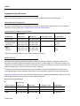
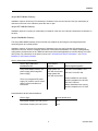
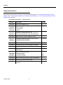
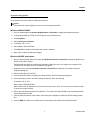
Job Aid
Pre-Installation Information—
S8700 Media Server
Avaya™ S8700 Media Server with MCC1 or SCC1 Media Gateway
Avaya™ S8700 Media Server with G600 Media Gateway
This job aid provides the information, hardware requirements, and computer hardware and software specifications
necessary for installing an Avaya™ S8700 Media Server with either MCC1/SCC1 Media Gateways or G600 Media
Gateways. It covers the following items:
■
Required information
■
Site Requirements
■
Required hardware
■
Computer specifications
Required information
Before going on site, make sure the customer has a local area network set up and running and a network
administrator available the day of the installation. Before beginning the installation, refer to the filled-out job aid
entitled Pre-Installation Network Planning Forms—S8700 Media Server.
Site Requirements
The Avaya S8700 Media Server control network components consist of the 2 media servers, the Ethernet
switch(es), and the 2 UPSs. These components are designed to be mounted in an open (not a cabinet), standard
19-in. (48-cm) equipment rack. We do not recommend a rack cabinet as it may not allow sufficient ventilation.
The customer is responsible for providing sturdy racks built to the EIA 310D (or equivalent) standards and
installing, securing, and grounding them per local code and rack specifications before the equipment is mounted in
them. The rack must be rated at a minimum of 200 pounds (90 kilograms). Make sure that the rail kits, required to
support the very heavy UPSs, are installed on the rack or available for installation. The customer must also provide
AC power to the rack from a nonswitched outlet.
1
October 2002
Job Aid
Equipment Specifications
This section provides specifications for the control network components and the media gateways.
Control Network Components
The Avaya S8700 Media Server control network components consist of the 2 media servers, the 1 or 2 Ethernet
switch(es), and the 2 UPSs. See ‘‘Control Network Components Specifications’’.
Control Network Components Specifications
Dimensions
Compenent
English (in.)
Metric (cm)
Us (height in rack)
Weight (lb/kg)
Media Server
3.5h x 17d x 17w
9h x 43d x 43w
2
25/11
Ethernet Switch:
P133G2/P134G2
P333T/334T
3.5h x 14d x 19w
3.5h x 18d x 19w
9h x 35d x 48w
9h x 45d x 48w
2
2
11,13/5,6
16.5/7.5
UPS:
700 VA
1500 VA
3.5h x 19d x 17w
3.5h x 24d x 17w
9h x 48d x 43w
9h x 30d x 43w
2
2
34/15
50/23
The internal room temperature must not exceed 43 deg C (110 deg F)
Media Gateways
The Avaya media gateways should be installed in a well-ventilated area. Maximum equipment performance is
achieved at an ambient temperature between 40 and 120 deg F (4 and 49 deg C) for a short-term operation (not
more than 72 consecutive hours or 15 days in a year) and up to 110 deg F (43 deg C) for continuous operation. The
relative humidity range is 10% to 95% at up to 84 deg F (29 deg C).
The other Environmental Considerations and System Protection requirements described in the Online Guide
Avaya MultiVantage Solutions Hardware Guide under "Site Requirements" apply to the Avaya media gateways.
‘‘Media Gateway Specifications’’ below provides the dimensions for 3 types of media gateways. Refer to the Avaya
MultiVantage Solutions Hardware Guide for more detailed information.
Media Gateway Specifications
Dimensions
Media Gateway
English (in.)
Metric (cm)
Us (height in rack)
Weight(lb/kg)
MCC1
70h x 28d x 32w
178h x 71d x 81w
NA
200–800/90–363
SCC1
20h x 22d x 27w
51h x 56d x 69w
NA
125/56
G600
12h x 22d x 19w
30h x 56d x 48w
7
35–39/16–18
October 2002
2
Job Aid
Avaya MCC1 Media Gateway
Installation requires 38 inches (97 centimeters) of clearance in the rear and at least 3 feet (91 centimeters) of
clearance in the front of the cabinet to permit the door to open.
Avaya SCC1 Media Gateway
Installation requires 16 inches (41 centimeters) of clearance in the rear, and 3 feet (91 centimeters) of clearance in
the front.
Avaya G600 Media Gateway
The Avaya G600 Media Gateway can be mounted at its midpoint by removing the mounting brackets and
remounting them at a medial position.
Installation requires 12 inches (30 centimeters) of clearance in the rear, and 18 inches (45 centimeters) of
clearance in the front, which is consistent with the EIA 310D data rack standards. In a multiple media gateway
configuration, the dimensions of the TDM/LAN cable require that media gateways be mounted directly over each
other (flush). For information on the power sources, see ‘‘Chassis Power Source Information’’. and ‘‘Circuit
Breakers for AC-Powered Chassis’’
Chassis Power Source Information
Chassis Style and Power
Distribution Unit
Power Source
Options
Avaya G600 Media Gateway: AC
power supply (650A integrated
power supply)
Single phase 120
VAC with neutral wire
Power Input Receptacles
120 VAC, 60 Hz NEMA 5-15R
240 VAC, 50 Hz IEC 320
Single phase 240
VAC with neutral wire
Japan installations use country
specific receptacles for 100 and
200 VAC, 50/60 Hz
There is no integrated DC power
supply. DC rectifiers can be used if
desired; follow manufacturer’s
instructions.
Mexico installations use country
specific receptacles for 127 VAC
Circuit Breakers for AC-Powered Chassis
Chassis Type
Circuit Breaker Size
Rack Mount Chassis (120 VAC) 60 Hz
15 A
Rack Mount Chassis (240 VAC) 50 Hz
10 A
3
October 2002
Job Aid
Required hardware
Before beginning the process, make sure you have the hardware listed in ‘‘List of Required Hardware—Control
Network’’ and ‘‘List of Required Hardware—SCC1/MCC1 Media Gateways’’ or ‘‘List of Required Hardware—G600
Media Gateway’’on hand.
List of Required Hardware—Control Network
Comcode
Description
Number
700169246
Avaya S8700 Media Server
2
Powerware 9125 uninterruptible power supply (UPS)
– US & Canada
– International
– Japan
2
408357002
408427409
700181928
Rail kits for mounting UPSs in rack
– 2-post rack (Powerware code: 05141562-0021)
– 4-post rack (Powerware code: 05146726-5501)
2
700230733
700230741
408427656
SNMP Network Interface Adapters for UPS
2
10/100BaseT Ethernet switch (if Avaya supplied)
– Avaya Ethernet P333 switch
– Avaya Ethernet P334 switch
1 or more
108563123
108644451
700169121
External V.90 56K USB modem with cable (if used)
2
700181050
128-MB PCMCIA PCCARD flashdisk (formatted)
2
700237332
Avaya MultiVantage Software CD
1
700252828
Avaya S8300 and S8700 Media Server Library CD
(555-233-824)
1
700170012
700178056
700178064
Green CAT5 Ethernet cables
– 5-meter (16 feet)
– 25-meter (82 feet)
– 50-meter (164 feet)
4
2-68
2-68
700169998
Blue CAT5 Ethernet crossover cable for duplication
1
700179898
Yellow single-mode fiber optic cable
1
700170053
Black CAT5 Ethernet crossover cable for laptop
computer
1
October 2002
4
Job Aid
List of Required Hardware—SCC1/MCC1 Media Gateways
Comcode
Description
Number
J58890X-1,
List 1, 4
Avaya Media Gateway
1-44
108774696
TN2312AP IP Server Interface circuit pack
1-44
700071251
IPSI Amphenol adapter (new installation only)
1/IPSI
700055015
TN799DP Control LAN circuit pack (if needed)
1-64
102631413
Control LAN Amphenol adapter (259A)
1/CLAN
108774696
TN2302AP IP Media Processor circuit pack
1-200
848525887
Media Processor Amphenol adapter
1/MedPro
700168727
Cable - IPSI to Maintenance MCC A carrier (Migration
only)
1-44
700168735
Cable - IPSI to Maintenance MCC B carrier to A
carrier (Migration only)
1-44
700168727
Cable - IPSI to Maintenance SCC A carrier (Migration
only)
1-44
700168834
Cable - IPSI to Maintenance SCC B cabinet to A
cabinet (Migration only)
1-44
List of Required Hardware—G600 Media Gateway
Comcode
Description
Number
J58890X-1,
List 1, 4
Avaya G600 Media Gateway (control)
1-64
J58890X-1,
List 1, 2
Avaya G600 Media Gateway (port)
1-192
TDM Kit
– TDM cable and EMI Gasket Installation Instructions
– Rack Mounting Template
– Circuit pack label
1-192
700017924
700017916
700207111
108774696
TN2312AP IP Server Interface circuit pack
1/PN
700071251
IPSI Amphenol adapter
1/IPSI
700055015
TN799DP Control LAN (C-LAN) circuit pack
1 or more
102631413
C-LAN 259A Adapter
1/C-LAN
108774696
TN2302AP IP Media Processor circuit pack
1-200
848525887
Media processor adapter
1/MedPro
5
October 2002
Job Aid
Computer specifications
The computer used for configuring the hardware must have the following minimum specifications:
■
Windows 95/98/NT4.0/2000/XP/ME operating system
■
32-MB RAM
■
40-MB available disk space
■
RS-232 port connector
■
Network interface card (NIC) with a 10/100 BaseT Ethernet interface
■
Ethernet crossover cable (MDI to MDI-X)
■
CD-ROM drive
It must also have the following software installed:
■
FTP program
■
Telnet program
■
Terminal emulation program (HyperTerminal or Avaya Terminal Emulation)
■
TCP/IP networking software (comes with Windows OS)
■
Web browser (Netscape 4.7.x [Netscape 6 is not currently supported] or Internet Explorer 5.x or higher only)
It must have the following files available:
■
License and Avaya Authentication (pasword) files. These must be downloaded from the Remote Feature
Activation (RFA) Web site.
The terminal emulation program port settings must be configured as follows:
■
9600 baud rate
■
No parity
■
8 bits
■
1 stop bit
October 2002
6
Job Aid
Network Configuration
A new network connection must be configured as follows:
NOTE:
Write down the original settings in case you need to change them back.
Windows 95/98/NT4.0/ME
1. On your desktop right-click Network Neighborhood > Properties to display the Network dialog box.
2. In the window select the TCP/IP that corresponds to your Ethernet card.
3. Click Properties.
4. Select Specify an IP address:
5. IP address: 192.11.13.5
6. Subnet Mask: 255.255.255.252
7. Click OK, OK to accept the information and close the windows.
8. Reboot the computer to effect the changes.
Windows 2000/XP instructions:
1. On your desktop (under Start for XP) right-click My Network Places > Properties to display the Network and
Dial-up Connections window.
Windows 2000 should have automatically detected the Ethernet card in your system and created a LAN
connection for you. More than one connection may appear.
2. Right-click on the correct Local Area Connection > Properties to display the Local Area Connection
Properties dialog box.
3. Select Internet Protocol (TCP/IP).
4. Click the Properties button to display the Internet Protocol (TCP/IP) Properties dialog box.
5. On the General tab, select "Use the following IP address." Enter the following:
IP address: 192.11.13.5
Subnet mask: 255.255.255.252
Make a note of any IP addresses or other entries that you have to clear. You may need to restore them later
to connect to another network.
6. Select "Use the following DNS server addresses." The entries for Preferred DNS server and Alternate DNS
server should both be blank.
7. Click the Advanced button at the bottom of the dialog box to display the Advanced TCP/IP Settings dialog
box.
8. Click the DNS tab. Make sure no DNS server is administered (the address field should be blank).
7
October 2002
Job Aid
October 2002
8