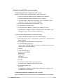
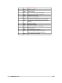
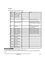
1
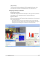
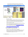
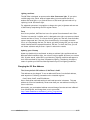
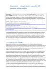
NXTCam v2 User Guide What is NXTCam NXTCam is a real-time image processing engine. Think of it as a vision sub-system with on-board processor and a protocol interface that is accessible through a standard NXT sensor port. This interface provides high-level, post-processed information of the image NXTCam sees. The processed information contains the bounding box coordinates of the objects of interest in view of NXTCam, in line tracking mode, this information contains coordinates of line segments. NXTCam does not send the image itself to NXT, however connecting NXTCam to a PC with USB cable, and using a Viewer and Configuration software, you can see the image on the PC. NXTCam Feature List The NXTCam provides following capabilities: • Track up to 8 different colorful objects at 30 frames/second • Configure the NXTCam using USB interface on Windows XP, Windows Vista. • Supports two tracking modes: Object tracking and Line tracking. • Provide real-time tracked object statistics (number of objects, color of objects, bounding box coordinates or line coordinates) through a standard NXT sensor port. • Tracked image resolution of 88 x 144 pixels at 30 frames/second • Perform full-resolution (176 x 144) pixels color image dumps to PC via USB port. • Maximum power consumption (42 mA at 4.7 V) • Uses NXT compatible I2C protocol for communications. • Supports Auto Detecting Parallel Architecture (ADPA) for NXT sensor bus. This means that NXTCam can coexist with LEGO or third party digital sensor on the same NXT port. ADPA support enables user to employ several sensors on the same port without the need of external sensor multiplexer, reducing the overall size without compromising the functionality. What you will need before using NXTCam Connector Cables For runtime operations (on the robot, in autonomous mode), the NXTCam connects to NXT on a sensor port using a standard connector cable that comes with NXT (the one with jacks similar to phone jacks). mindsensors.com 1/12 For offline operations (for programming and configurations), NXTCam connects to PC using mini-USB cable. (This is in addition to the cable you would use to connect NXT to your PC). Adjacent picture shows the mini-USB connector you would need on your USB cable, this connector is commonly used for digital cameras. If you need to acquire a cable separately, it should be a ‘5 wire’ cable. USB Driver installation In order for NXTCam to work properly, you will need to install USB drivers for your operating system. Currently support exists for: Windows XP (i386 and AMD processors) Windows Vista (i386 and AMD processors) Mac OS X v10.4.10 (PowerPC G4) Download the drivers and installation instructions from following location: http://www.mindsensors.com/NXTCam_Driver_Installation.htm Viewer and Configuration Software To see the picture that’s in the field of view of NXTCam, capture that picture for analysis and configure the Colormaps for onboard processing, you will need to install and use Viewer and Configuration software on your PC. For MS-Windows XP/Vista, download Viewer and Configuration software from: http://nxtcamview.sourceforge.net/ For Macintosh, download Viewer and Configuration software from: http://www.mindsensors.com/index.php? module=documents&JAS_DocumentManager_op=viewDocument&JAS_Document_id= 53 Programming Environment(s) NXTCam is supported for use in NXT-G using a custom block. Download the block from following URL: http://www.mindsensors.com/NXTCam_NXT-G_Block.htm This block provides functionality for tracking objects based on the Colormaps downloaded on NXTCam. Follow the installation instructions provided at this URL to install the block. Note: While using with NXT-G, ensure to use firmware version 1.05. LeJOS API’s are available at: http://lejos.sourceforge.net/p_technologies/nxt/nxj/api/lejos/nxt/NXTCam.html RobotC API’s are available at: http://www.mindsensors.com/index.php? module=documents&JAS_DocumentManager_op=viewDocument&JAS_Document_id= 50 mindsensors.com 2/12 NXC/NBC Library functions are available at: http://www.mindsensors.com/index.php? module=documents&JAS_DocumentManager_op=viewDocument&JAS_Document_id= 57 Connecting NXTCam Wiring for NXTCam NXTCam may be connected to any of the sensor ports of NXT using standard NXT connector cable. In your program, select the appropriate port number to which NXTCam is connected. WARNING Do not connect the NXTCam to any motor port, as the voltage applied by the motor port may damage the electronics of NXTCam. During offline operations, such as programming and configuration, NXTCam must be connected to PC (using USB cable) as well as NXT (using standard NXT connector cable) while NXT is powered ON. During runtime (or autonomous) operations on NXT, the USB connection to PC must be removed. NOTE: While NXTCam is connected to NXT as well as PC, the PC communication takes priority over any other communication. In other words, while NXTCam is connected to PC as well as NXT, if you run a program on NXT, it will not be able to talk to NXTCam. Mounting NXTCam on your contraption The holes on the NXTCam enclosure are designed for tight fit of Technic pins (or axles) with ‘’ cross section. The holes however are not designed for repeated insertions/removals of these pins. To mount NXTCam v2 on your contraption we suggest that you use two dark gray ‘Technic Axle 3 with Stud’ as shown. Insert axles from the front (lens side) of the NXTCam and secure with a bushing on the back or mount it on your contraption directly. Alternately, you may use blue ‘Technic Axle Pin with Friction’, as shown. While disassembling contraption, leave the axles and/or pins on NXTCam. mindsensors.com 3/12 LED on NXTCam The LED on NXTCam lights up whenever NXTCam is supplied with power. Under normal operations, the power will be supplied by NXT from the sensor port. Configuring Colormaps in NXTCam Default Object Colormap The NXTCam is shipped with a default Colormap to track a light source. Download a test program or write a test programs, and try tracking a light source. Objects of interest Below are screen dumps of NXTCamView software, showing objects of interests and their tracking information. The top left window in the picture below shows the field of view of NXTCam. The objects of interest from this view are the red and blue pens. In the object tracking mode, the bounding box coordinates are returned, as shown: mindsensors.com 4/12 In line tracking mode, beginning point and end point coordinates of a line representing the object are returned. In the following picture, the bounding boxes are drawn for the line coordinates received from NXTcam: More about Colormaps The objects of interest are recognized by NXTCam by matching the stored color values with the captured image. To do that, color values of the objects of interest need to be stored on NXTCam. These color values are known as Colormaps. NXTCam can store up to 8 Colormaps and provide processed information of the objects matching those Colormaps. For more information on how to pick Colormap values of your objects of interest and how to store them on NXTCam using the NXTCamView software, please refer to section ‘teaching NXTCam colors’ from URL: http://nxtcamview.sourceforge.net/ Also watch a demo video ‘Capture and Select’ at following URL: http://nxtcamview.sourceforge.net/DemoScreenCam.htm Tips on using NXTCam in your environment Object Colors in Line Tracking Vs Object Tracking Modes In the object tracking mode, you can track objects comprising of 8 distinct colors. While selecting colors, avoid any overlap between colors of different objects. In line tracking mode, only the first color from the Colormap is used, and it is recommended to limit the number of colors to one. mindsensors.com 5/12 Lighting conditions The NXTCam is designed to operate under white fluorescent light. If you notice reddish image color, which tends to happen when your environment has lot of ambient Infrared light, try to find the source of Infrared light and reduce it by replacing it with fluorescent light. For advanced operations it is possible to change color gain, brightness and contrast of NXTCam by manipulating the I2C register values. Focus As a factory default, NXTCam lens is set for optimal focus between 2 and 4 feet. The lens is screwed in it’s holder and it is designed to be tight to prevent accidental rotation and loss of focus. To refocus the lens, gently turn the lens from the holder, capture images and see if the new focus is satisfactory. Do not apply excessive force, as it may damage the lens. For better grip while turning lens, you may wrap a rubber-band around the exposed threads of the lens. To check the focus, you can use Viewer software and perform a 'capture' and see the results. Updating your Colormap Human eye (and brain) is conditioned to adapt to ambient light conditions and see. Whereas based on ambient light, the colors of objects appear different to a camera CCD. In other words, a blue ball in your laboratory lighting conditions will appear to be a different shade of blue than in Gymnasium lighting. Considering this aspect, ensure to update your NXTCam Colormap based on your final lighting conditions. Changing the I2C Bus Address The factory default I2C address of NXTCam is 0x02. This address can be changed. To set an address different from default address, send sequence of following commands on the command register: 0xA0, 0xAA, 0xA5, <new I2C address> Note: Send these commands with no break/read operation in between. This new address is effective immediately. Please note down your new address carefully for future reference. Alternately, you can download address scan and change functions written in RobotC from following URL, and change them to suit your needs: http://www.mindsensors.com/RobotC_Utility_Programs.htm mindsensors.com 6/12 Troubleshooting NXTCam communication Troubleshooting NXTCam communication with your PC To ensure USB drivers are installed properly, follow these steps: 1. Ensure to install the USB drivers as mentioned in this document. 2. Connect the NXTcam using a USB cable to your computer. 3. From Start menu -> Right click on Computer, select 'Properties', select 'Hardware' tab, and select the 'Device Manager'. 4. Expand the 'Universal Serial Bus Controller' entry. 5. You should see 'NXTCam' listed. 6. In the same Device Manager, Expand ‘Ports (COM & LPT) entry. 7. You should see a COM port listed for NXTCam (this is the COM port you should use for your viewer software configuration). To ensure actual USB communication, follow these steps: 1. Connect the NXTcam using a USB cable to your computer. 2. Run Hyperterminal: Start -> All Programs -> Accessories -> Communication -> Hyper Terminal 3. Give a name for the configuration, say ‘mynxtcam’. 4. In the next dialog box specify: Connect Using: <NXTCam COM Port> (the port you noted from Ports (Com and LPT) entry in Device Manager) 5. Click OK. 6. In next window Specify: Bits per second: 115200 Data bits: 8 Parity: None Stop bits: 1 Flow Control: None 7. Click OK. 8. In the main terminal window, just press <enter> You should get a response from NXTCam as ‘NCK’ 9. In the same window, type: GV<enter> You should get a response from NXTCam as ‘NXTcam V n.n’ (where n.n is your NXTcam version number) Troubleshooting NXTCam communication with your NXT Ensure to install NXT-G blocks for NXTCam as mentioned above in the document. mindsensors.com 7/12 1. Connect your NXT to your PC using it’s standard USB cable. 2. Connect your NXTCam to NXT Port 1 using standard NXT sensor cable. 3. Run NXT-G software on your computer. 4. Power on the NXT. 5. Start a New Program (say Untitled-1), and from Advanced Block Palette, drag and drop the NXTCam block in it. 6. Click on the block, and examine the bottom left corner of NXT-G window (where block control panel is located). 7. You should see NXTCam version number shown in the bottom left corner, as shown in the adjacent picture. 8. If the NXTCam is not connected correctly to your NXT, this status will indicate ‘No Device’. If that happens, ensure the port and Address in your program match to what’s on NXTCam. Reference Information Wiki for NXTCamView, NXTcam and related Projects and findings Visit following URL for the wiki http://nxtcamview.wiki.sourceforge.net Open Source Software and Hardware NXTCam is based on AVRcam, and is Open Source using GNU license. We encourage you to improve the source code and features and inform us the changes for inclusion in future releases. Visit following URL to download the source code and related docs. http://www.mindsensors.com/NXTCam_Source_Code.htm I2C Operations Pins used: SDA(1), GND(2), SCL(3), +5V(4) Following table lists the register definitions and setup commands: Commands ASCII Hex Action A 0x41 Sort tracked objects by size B 0x42 Select Object tracking mode C 0x43 Write to Camera Registers Use extreme CAUTION when using command C since this can stop your camera working properly. In case this happens, please power off your NXTCam mindsensors.com 8/12 and power it on again. D 0x44 Disable Tracking E 0x45 Enable Tracking G 0x47 Get the Color map from Camera Engine H 0x48 Read data from the Camera Registers I 0x49 Illumination on (Future) L 0x4C Select Line tracking mode N 0x4E Set ADPA mode ON (setting stored in NVRAM) O 0x4F Set ADPA mode Off (default) (setting stored in NVRAM) P 0x50 Ping camera Engine R 0x52 Reset Camera Engine S 0x53 Send the color map to camera Engine T 0x54 Illumination Off U 0x55 Sort tracked objects by color V 0x56 Get camera Engine firmware version No, Read resulting string at 0x42 (12 bytes). X mindsensors.com 0x58 Do not Sort tracked objects 9/12 I2C Registers: The NXTCam appears as a set of few registers as follows. Register Read Write 0x00-0x07 Software version – (Vn.nn) - 0x08-0x0f Vendor Id – mndsnsrs - 0x10-0x17 Device ID – NXTCam - 0x41 - Command This register is command register. A command written here will be executed. 0x42 Number of objects detected - Shows how many objects are being tracked. Zero indicates that there are no objects being tracked. 0x43 1st object color - This is the first object color as per the sorting method selected. 0x441 1st object - X upper left Upper left X coordinate of first object 0x45 1 object - Y upper left Upper left Y coordinate of first object 0x46 1st object - X lower right Lower right X coordinate of first object 0x47 1 st Comments 2 st 1 object - Y lower right nd 0x48 2 0x49-0x4C 2nd object co-ordinates 0x4D 3rd object color 0x4E-0x51 3rd object co-ordinates 0x52 4th object color 0x53-0x56 4th object co-ordinates 0x57 5th object color 0x58-0x5B 5th object co-ordinates 0x5C 6th object color 0x5D-0x60 6th object co-ordinates Lower right Y coordinate of first object object color In case of line tracking mode, these are coordinates of beginning and end points of the line. 2 This repeats for all 8 objects. Please note that object position and coordinate are overwritten if new object is detected, otherwise previous value is retained. mindsensors.com 10/12 3 4 Register Read 0x61 7th object color Write Comments 0x62-0x65 7th object co-ordinates 0x66 8th object color 0x67-0x6A 8th object co-ordinates 0x6B No. of registers to Read No. of registers to Write This is the number of registers you need to read or write from camera image sensor 0x6C 1st Camera register Address 1st Camera register Address 0x6D3 1st Camera register Data 1st Camera register Data ……………………….. ………………………………………….. …………………………… th 0x7A 8 Camera register Address 8th Camera register Address 0x7B 8th Camera register Data 8th Camera register Data 0x804 Color map data Red 0 Color map data Red 0 0x80 Color map data Red 0 Color map data Red 0 0x81 Color map data Red 1 Color map data Red 1 0x82 Color map data Red 2 Color map data Red 2 1st register Data read from image sensor or written to image sensor 0x80 – 0xAF - These registers are used for Colormap data reading and writing If you need to read image sensor register 0x00 (i.e. 1 register) then follow this: Write 0x01 to register 0x6B, Write 0x00 to register 0x6C Run command ‘H’ Results will be stored in register 0x6D If you need to write to image sensor register 0x00 (i.e. 1 register) then follow this: Write 0x01 to register 0x6B, Write 0x00 to register 0x6C, Write data to register 0x6D Run command ‘C’ If you need to read Colormap data from camera engine, then follow this: Run command ‘G’ Read registers 0x80 – 0xAF. If you need to write Colormap data to camera engine, then follow this: Write your color map data in registers 0x80 – 0xAF, Run command ‘S’ mindsensors.com 11/12 Register Read Write 0x83 Color map data Red 3 Color map data Red 3 0x84 Color map data Red 4 Color map data Red 4 0x85 Color map data Red 5 Color map data Red 5 0x86 Color map data Red 6 Color map data Red 6 0x87 Color map data Red 7 Color map data Red 7 ..................... ………………………………………………. …………………………………… 0x8F Color map data Red 15 Color map data Red 15 0x90 Color map data Green 0 Color map data Green 0 0x91 Color map data Green 1 Color map data Green 1 ..................... ………………………………………………. …………………………………… 0x9F Color map data Green 15 Color map data Green 15 0xA0 Color map data Blue 0 Color map data Blue 0 0xA1 Color map data Blue 1 Color map data Blue 1 ..................... ………………………………………………. …………………………………… 0xAF Color map data Blue 15 Color map data Blue 15 mindsensors.com Comments 12/12