1
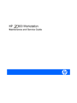
Model 2000 Series
Operators Manual
Model 2000 Series
2001, SpectraSensors, Inc.
1
Table of Contents
Introduction
Theory of Operation
Specifications
3
4
Installation
Introduction
Initial Inspection
Location Requirements
Mounting Procedure
Gas Connections
Electrical Connection
Output Signal Connection
RS-232 Output
Calibration
Power up Sequence
5
6
6
7
8
9
12
15
15
16
Operation
Specification of Proper Use
Keypad Functions
Modes (User Password)
Power-down Procedure
17
17
19
27
Maintenance
Reducing Contamination of Gas Sampling Lines
Cleaning Procedure
28
28
Troubleshooting
Troubleshooting
Warranty Information
33
35
Service Contact
If the above troubleshooting steps do not result in a resolution of the problem,
you should call the sales representative that sold it to you. Always contact your
sales representative before returning units to factory. The representative can help
with additional troubleshooting procedures and can diagnose whether the unit can
be serviced on-site or should be returned to the factory for repair. Your sales
representative is:
2001, SpectraSensors, Inc.
2
Introduction
About SpectraSensors
SpectraSensors is located in Altadena, California, just a short distance from the
California Institute of Technology's Jet Propulsion Laboratory (JPL) where the
basic technology behind the products offered by SpectraSensors was developed.
This technology was first utilized for accurate measurements of gases in the
Earth's atmosphere in the early 1980s, and recently was incorporated into
miniaturized and space-qualified instruments for Mars research. SpectraSensors
obtained the commercial rights to this NASA technology, and is now offering
state-of-the-art gas sensors.
About the Model 2000 Series Gas Sensor
The 2000 series of gas sensors are Tunable Diode Laser (TDL) absorption
spectrometers operating in the near infrared wavelength region. Each 2000 sensor
contains a TDL light source and detector configured to allow high sensitivity in a
compact package, microprocessor-based electronics, and software incorporating
advanced operational and data processing algorithms. This manual will use the
two-channel system as a reference for description. All comments also apply to
the single channel sensors, except where indicated.
The 2000 Series is designed for use at natural gas sampling stations, extractive
analysis installations, or wherever fast response and high accuracy measurements
are required over a wide measurement range. It is a high performance instrument,
capable of measuring moisture and carbon dioxide in methane and other gases
without regard to corrosive gases and contamination from other gas phase
constituents in the stream.
Several patents protect the TDL absorption technology incorporated in
SpectraSensors' gas analyzers.
Theory of Operation
Both H2O and CO2 are measured by monitoring their absorption of laser light at
specific wavelengths in the near-infrared (near-IR) wavelength region near 2µm.
The human eye responds to light in the range of approximately 0.4µm (deep
violet) to 0.8µm (deep red), but most molecules “respond” to light at longer
wavelengths that are invisible to the human eye (the infrared region). By using a
laser that operates precisely at a wavelength where H2O, or CO2, (many other
gases can also be measured using this technique) absorbs, it is possible to
accurately determine the abundance of the gas by measuring the amount of light
that is absorbed by the molecules.
SpectraSensors’ can provide references that describe in detail how our gas
sensors operate. However, a detailed description is beyond the scope of this user
manual.
2001, SpectraSensors, Inc.
3
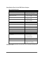
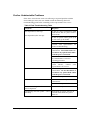
Specification Sheet for the 2000 Series Analyzer
Table 1 Specification sheet
Measurement Range
Moisture Concentration (H20)
0 to 20 lbs/MMscf
Dew/Frost Point
-70 to +-30 °C (-94 to -22°F)
Carbon Dioxide (CO2)
0 – 10%
Reading Accuracy (H2O)
± 2% of reading, or ±4 ppmv,
whichever is greater
Reading Accuracy (CO2)
± 2% of reading, or ±400 ppmv,
whichever is greater
Response time
1 second continuous
(software adjustable)
updates
Normal operating environment range
Temperature
-20 to +50°C (-4 to +122°F)
Pressure
0.7 to 1.7 Bar (10.3 to 25.0 PSA)
3 Bar (30 PSIG) absolute maximum
Gas flow rate
0.3 to 10 Liter/minute
Glycol contamination sensitivity
None for gas phase glycols
Sample cell construction
300 series polished stainless steel
Input Voltage
100-250 VAC, 50-60 Hz standard
Current draw @ 120 VAC
1 amp maximum
Outputs
Moisture, dew point, CO2 %, pressure, and
temperature
4 line LCD display
RS-232 serial port
4-20 ma current loop
(concentration only)
Data Input
16-key keypad
Weight
25 lbs (11.5 kg)
Dimensions (box)
Wide: 18.8-in. (478-mm)
Deep: 5.3-in. (135-mm)
Height: 17.5-in. (444-mm)
NOTE: These are typical specifications. Exact performance will vary depending on installation and
operating environment.
2001, SpectraSensors, Inc.
4
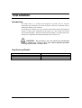
Installation
Introduction
The 2000 Series is a compact unit designed to provide years of accurate,
dependable gas monitoring. All of the electronic controls are contained inside a
NEMA 4X stainless steel enclosure.
The 2000 Series contains one or two sensitive measurement heads (depending on
number of target gases analyzed). Each consists of a gas sample cell and an
optical head assembly. Inside the optical head assembly is a tunable diode laser
and optical components that should be handled with extreme care.
CAUTION! – Do not hold or carry the unit by the measurement
heads or sample cells. Doing so may cause optical alignment problems
affecting the performance of your sensor.
Key Hook-up Details
Gas Connection
Power Cord Diameter
Signal Cable Diameter
Conduit Knock Hole
2001, SpectraSensors, Inc.
¼" O.D. Tube
0.31" to 0.56"
0.31" to 0.56"
½" K.O.
5
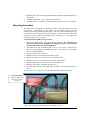
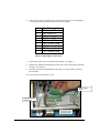
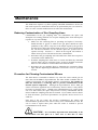
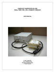
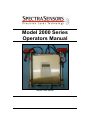
Sample cell
upper flange
Optical head
assembly
Sample cell
Keypad
Left sample
cell gas line
connection
Sample cell
lower flange
Serial and 4-20mA
interface connections
Power connections
Right sample
cell gas line
connection
Figure 1 Main external components identified on 2000 Series gas sensor.
Initial Inspection
The 2000 Series should be inspected for damage. The contents of the container
should include:
§
§
The 2000 Series stainless steel enclosure with measurement leads
Operators Manual
Inspect the unit for dents or dings in the enclosure and keypad. Inspect the inlet
and outlet connections for damage. Report any damage to the shipping agent.
§
Location Requirements
§
§
AC power (100-250VAC, 50/60 Hz). The 2000 Series is equipped with a
universal power supply that will accommodate both US (110 VAC @ 60 Hz)
and European (250 VAC @ 50Hz) AC power configurations
Mounting surface: wall-mounted, or tabletop mounted.
2001, SpectraSensors, Inc.
6
§
Sampling lines with coalescing and particulate inline filters and shutoff valve
on inlet line
§
§
Ambient temperature: -4°F (-20°C) to 122°F (50°C)
Ambient pressure: 10 PSIA to 16 PSIA (sample cell pressure: 10 - 25 PSIA)
Mounting Procedure
The 2000 Series is designed to be bolted to a wall or other flat surface that is free
of vibrations. Minimizing the gas volume of the sample system and using
stainless steel tubing optimizes performance. The only critical mounting issue is
to mount the unit so that the inlet and outlet line will reach the inlet and outlet
connections on the chassis and still have some flexibility (i.e. the sample lines
will not be under excessive stress).
To wall mount the 2000 Series gas sensor:
1. Unpack the 2000 Series from the shipping container. Be careful not to
shock the instrument by dropping it or banging it against a hard surface
as this could disturb the optical alignment.
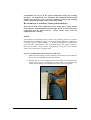
2. The 2000 Series has 4 mounting tabs with a 0. 3-in. hole in each tab (see
Figure 2). SpectraSensors recommends using ¼" lag bolts (or ¼-20 machine
screws if through bolted).
3. Position the unit where desired.
4. Mark the hole in one of the top tabs with a pencil.
5. Mark a second top screw location 8" over from the first.
6. Mark the lower screw locations 12-3/4" below the top holes.
7. Drill the appropriate size hole for the screws being used.
8. Hold the unit in place and insert the top screws.
9. Insert the bottom screws and tighten all four screws. The unit should be very
secure.
10. The unit is now ready to receive the inlet and outlet sampling gas lines.
Foot of mounting
bracket (identical on
each rear corner of
enclosure)
Figure 2 Main external components identified on 2000 Series gas sensor.
2001, SpectraSensors, Inc.
7
Gas Line Connection Procedure
The 2000 Series is configured to accept ¼" O.D. sampling lines (inlet and outlet)
via compression fittings mounted on the chassis.
CAUTION! – The inlet line should be equipped with a membrane or
coalescing filter to prevent liquid from entering the sample cell and possibly
accumulating on the internal optics.
It is important that the internal optical elements remain clean for proper readings.
The inlet line should also have a shutoff valve to prevent gas flow into the
analyzer when it is not in use. The outlet line of the 2000 Series is connected to a
¼-in. O.D. stainless steel line that vents the sampled gas to ambient air outside
the sampling station. After the inlet and outlet lines have been connected, the
connections should be checked for leaks. The minimum flow rate through the
analyzer should be 0.3 liters per minute (L/min). Optimum sample cell pressure
is just above ambient pressure for the installation location. Sample cell pressure
is displayed on the front panel LCD.
CAUTION! – The pressure in the sample cell must not exceed 30
PSIG (3 Bar A). Higher pressures will cause catastrophic damage to the
instrument. We recommend that there be no restrictions in the output vent
line of the sample cell and that a pressure relief valve be used on the input
line in case of regulator failure.
To make the gas line connections:
1.
To avoid initial contamination entering the analyzer, establish the gas flow
and blow any contamination from the line before connecting.
2. Align the inlet and outlet tubing to gas sensor inlet and outlet connections.
3. Be sure that there is no stress on the tubing when it is aligned to the gas
sensor.
4. Install union type swage fittings to connect the inlet and outlet tubes to the
gas sensor.
5. Follow manufacturer's recommended procedure for tightening the fittings.
6. Open the shutoff valve on inlet line.
7. Check the connections for gas leaks.
2001, SpectraSensors, Inc.
8
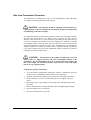
Electrical Power Connection Procedure
Electrical power can be connected to the unit with either a power cord or through a
conduit. A ½" knockout is provided at the lower right of the unit to accomplish this. The 2000
Series is equipped with either a universal power supply that will accommodate both US (115
VAC @ 60 Hz) and European (240 VAC @ 50Hz) AC power configurations or a DC input
power supply.
CAUTION! – Before attempting to attach the power wiring to the
gas sensor, be sure that there is no power present on the wires.
To connect an electrical power cord to the unit:
1. Open the enclosure door, being careful not to disturb the electrical assembly
inside.
2. Thread a 120VAC power cord through the strain relief fitting supplied with
the unit. See figure 3. The power cord must be the three wire grounding
type. The power cable should have at least 16 gauge conductors. The strain
relief fitting is designed to accommodate cords with outside diameters from
0.31" to 0.56".
Power supply
access point
Figure 3 Thread power supply through the right side access point at the bottom of the enclosure.
2001, SpectraSensors, Inc.
9
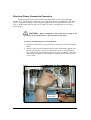
“Neutral” terminal
connection
“Hot” or “Line”
terminal connection
Figure 4 Connect neutral line to terminal marked “NEU”, and hot line to terminal marked “LINE”.
3. Remove at least 8" of the jacket to expose the three conductors within.
4. Cut the black wire (line or hot) and the white wire (neutral) about 2" from the
jacket and strip off 3/8" of insulation from the ends.
5. Loosen the terminal screw marked LINE, insert the black wire, and tighten
the terminal screw. Be sure that the terminal is contacting the conductor and
not clamped onto the insulation. See figure 4.
6. Loosen the terminal screw marked NEU, insert the white wire, and tighten
the terminal screw. Be sure that the terminal is contacting the conductor and
not clamped onto the insulation.
7. Crimp a #10 ring terminal to the green (ground) wire in the cord. Be sure
that the terminal is the correct size for the gauge of wire being used and the
crimp holds both the insulation and the wire. Follow the terminal
manufacturer's instructions for preparing and crimping the terminal.
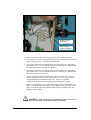
8. Remove the grounding screw at the bottom right of the electrical panel. See
figure 5. Insert the screw through the ring terminal on the green wire of the
power cord, through the ring terminal of the internal grounding wire, and
tighten it into the panel.
CAUTION! – Failure to properly ground the gas sensor can create a
high voltage shock hazard. Follow the instructions carefully.
2001, SpectraSensors, Inc.
10
Ground Contact
Figure 5 Connect the green wire to the ground contact in the lower left corner of the enclosure.
9. Tighten the strain relief mechanism so that it is grips the power cord.
10. Close and lock the enclosure door.
11. Plug the power cord into an AC socket. The socket should be fused for 15A
or less. Because the plug on the power cord is the primary power disconnect
means, the AC socket must be located within 10 ft of the gas sensor.
To hardwire power to the unit through a conduit:
CAUTION! – Before attempting to attach the power wiring to the
gas sensor, be sure that there is no power present on the wires.
1. Open the enclosure door, being careful not to disturb the electrical assembly
inside.
2. Remove the cord strain relief fitting from the power knockout.
3. Replace the strain relief with a NEMA 4X rated conduct hub.
4. Run conduit from the AC panel to the conduit hub. Since the breaker or switch
in the AC panel will be the primary disconnect means for the gas sensor, the AC
2001, SpectraSensors, Inc.
11
panel must be located within 10 ft. of the gas sensor. The gas sensor should be
on a circuit that is protected at 15A or less.
5. Pull Ground, Neutral, and Hot wires into the electrical enclosure.
6. Attach the Neutral and Hot wires to the power terminal strip as shown in figure 3.
7. Crimp a #10 ring terminal to the green (ground) wire. Be sure that the terminal is
the correct size for the gauge of wire being used. Follow the terminal
manufacturer's instructions for preparing and crimping the terminal.
CAUTION! – Failure to properly ground the gas sensor can create a
high voltage shock hazard. Follow the instructions carefully.
8. Turn on power to the gas sensor circuit.
Output Signal Connection Procedure
The 4-20mA and serial outputs are supplied from a mating terminal block inside
the unit. Connections can be made with a customer supplied cable through the
strain relief fitting supplied with the gas sensor or by running the signal wires
into the enclosure through a ½" conduit.
CAUTION! – Be sure the power to the unit is turned off before
opening the gas sensor enclosure and making any connections.
Note that the 4-20mA outputs are factory set to source current. If a passive current
loop is required, the jumper on the current loop board may be moved from the “A”
(active) position to the “P” (passive) position.
To connect the 4-20mA and serial outputs through a cable:
1. Disconnect power from the unit.
2. Open the enclosure cover, being careful not to disturb the electrical assembly
inside.
3. Thread the signal cable through the strain relief fitting into the enclosure.
The strain relief fitting is sized to accommodate cables with outer diameters
from 0.31" to 0.56". SpectraSensors recommends that a cable with an
individually shielded pair for each signal be used for the signal connections.
4. Strip back the jacket and insulation of the signal cable enough that it can be
connected to the mating terminal block.
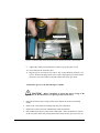
5. The mating terminal block can be pulled up from its base to make cable
connection easier. See figure 6.
2001, SpectraSensors, Inc.
12
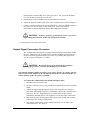
6. Table 2 shows the pin number for each of the output signals. Note that there
is a single ground connection shared by all of the signals.
Pin #
1
2
3
4
5
6
7
8
9
Signal Description
CH1 Serial RX
CH1 Serial TX
COM Serial Gnd
CH2 Serial RX
CH2 Serial TX
CH1 Current Loop +
CH1 Current Loop CH2 Current Loop +
CH2 Current Loop -
Table 2 Output Signal Connections
7. Connect the output wires to the desired terminals. See figure 7.
8. Reinsert the matting terminal block into the base and verify that the terminals
are tight. See figure 8.
9. Cinch the strain relief mechanisms so that they are snug with the outside of
the enclosure.
10. Close and lock the enclosure cover.
Power supply
block
4-20 mA and serial
output block
4-20 mA and serial
output block base
Figure 6 Remove the mating terminal block from base by hand.
2001, SpectraSensors, Inc.
13
Figure 7 Insert signal wires into terminals as shown in Table 2
Figure 8 Replace block on base and check all terminals are tight.
2001, SpectraSensors, Inc.
14
To connect the 4-20mA and serial outputs through a cable:
1. Disconnect power from the unit.
2. Open the enclosure cover, being careful not to disturb the electrical assembly
inside.
3. Remove the cable strain relief fitting and replace it with a NEMA 4Xrated
conduit hub.
4. Run conduit to the gas sensor and pull signal wires through the conduit.
SpectraSensors recommends the use of shielded wire to prevent signal
interferences.
5. Follow steps 4 through 10 above for connecting the signal wires to the
terminal block.
RS-232 Output
The RS-232 presents a string of data to a serial device. The serial device is
typically a computer terminal running HypeTerminal or other serial port
software. The serial port should be set for 9600 baud, 1 stop bit, no parity, and
no handshake. The RX output is connected to pin 3 on the computer's serial
input. The TX output is connected to pin 2 on the computer, and the GND is
connected to pin 5.
The data string is space delimited with a carriage return at the end of each line.
The data are output in the following order:
Water vapor concentration (if a water channel)
Dewpoint (if a water channel)
CO2 concentration (zero unless a CO2 channel is present)
Pressure
Temperature
2F signal
DC signal
Peak Position (Index)
Null
Calibration
The instrument is calibrated at SpectraSensors against standard (assayed) gas
mixtures, and should not be adjusted in the field. Unlike aluminum oxide or
electrolytic sensors that are in contact with the sample gas, the laser used to make
the measurement in the 2000 Series simply passes through the sample cell and
there are no sensors in contact with the gas. So drift or contamination from
contaminants (such as glycols or amines in the gas phase) is not possible.
If, however, there is any question or doubt about the 2000 Series readings, a
calibration using a Certified Master Class Calibration Standard, or a chilled
2001, SpectraSensors, Inc.
15
mirror hygrometer, may be used to verify measurement accuracy. Note that any
H2O calibrations must be performed with the same type of background gas
that is used in normal operation.
Power Up Sequence
When the 2000 Series gas sensor has been mounted, the gas sampling lines
connected and checked for leaks, and the (optional) output signal wires
connected, the unit is ready to apply AC power. It is possible to apply AC power
before the gas lines are connected to ensure the unit is functional, but ambient air
contains levels of water vapor that are much higher than the instrument is
designed to measure. Therefore, valid H2O readings cannot be obtained until
sample gas is flowing through the sample cell.
To power up the 2000 Series:
Apply AC power by plugging in the gas sensor (if cord connected) or by
energizing the circuit if the gas sensor is hard wired. Note that there is a 500
mA slow-blow fuse located on the bottom right hand side of the chassis.
When AC power is applied to the 2000 Series, the system will go through a 15
second initialization period. The LCD on the keypad will display the word
INTIALIZING… and then start counting down from 15. The keypad will not
respond to key presses during this time period. Allow 3 additional minutes for the
2000 Series to stabilize before recording measurements.
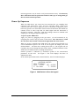
Normal operation is indicated by continuous updates of the measurement
parameters on the LCD. See Figure 9. The LCD displays four lines of
alphanumeric data.
In the normal operational mode ("Normal Mode"), the LCD readout displays:
<NORMAL MODE>
H2O: 120.62pmv
CO2: 2.33%
DP: -41.00C
P: 1011.8mb
T: 23.20C
Figure 9 2000 Series LCD on the keypad
2001, SpectraSensors, Inc.
16
Operation
Specifications for Proper Use
The 2000 Series is designed specifically to measure levels of moisture, and
carbon dioxide in a gas stream. It also reports dew point, temperature and
pressure of the sampled gas.
Although the unit can easily be dismounted and moved from one sampling
station to another, it is designed to be a stationary measuring device. It should be
securely mounted during normal operation.
Opening of the main enclosure cover is required for installation only. Thereafter,
you will rarely need to open the cover of the main enclosure for inspection or
maintenance. Subsequent to installation, do not open the enclosure for this
purpose unless directed to do so by a service representative.
The measurement heads may be disassembled for cleaning purposes (see the
Maintenance Section of this manual). The two main parts of the measurement
head are the gas sampling cell and the optical head assembly. The gas sampling
cell may be separated from the optical head assembly, and can be further
disassembled for mirror cleaning purposes from time to time. In no case,
however, will the operator need to disassemble the optical head assembly.
CAUTION! – Note the enclosure seal, used to prevent inadvertent
tampering with the device. It is imperative that the operator not attempt to
compromise the seal of the optical head assembly enclosure. Doing so will
result in loss of device sensitivity and inaccurate measurement data. Repair
of this situation must be handled by the factory and is not covered by
warranty.
Keypad Functions
The keypad allows the operator to modify certain parameters that control the
2000 Series. However, once the unit has been properly installed and normal
operation has been established, there should be no need to alter the operational
parameters. Measurements of H2O, CO2, Dew Point, Temperature and sample
cell Pressure are continuously displayed on the LCD display. For single channel
H2O-only systems, the CO2 value will always display as zero.
NOTE: To activate any functions on the keypad, press the “#” key and then
press a number to select “Mode” or the TEST key. If the “#” key is not
pressed before pressing a Mode or function key, there will be no response.
When the “#” key is pressed, the word “MODE” will be displayed on the
LCD. At this point the unit will wait for a second key to be pressed before
responding.
2001, SpectraSensors, Inc.
17
Figure 10 2000 Series Keypad
2001, SpectraSensors, Inc.
18
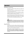
Modes
The following modes can be accessed from the keypad by pressing the “#” key
and then entering 1, 2, 3, 4 or “Test”.
§
Mode 1 is Normal Display Mode.
§
Mode 2 provides change of parameters for H2O measurement.
§
Mode 3 provides change of parameters for CO2 measurement
§
Mode 4 displays System Diagnostic Parameters for H2O
§
Mode 5 displays System Diagnostic Parameters for CO2
§
Mode 6 outputs spectra and calculations to serial port
§
Mode “Test” displays H2O System Test parameters
Mode 1 (Normal Display Mode)
#
+
1
Mode 1 continuously displays updated measurements.
<NORMAL MODE>
H2O: 120.62pmv
CO2: 2.33%
DP: -41.00C
P: 1011.8mb
T: 23.20C
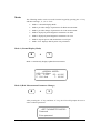
Mode 2 (H2O Measurement Parameter Change)
#
+
2
After pressing the “#” key and then “2” key, the LCD will prompt the user to
enter a numeric password.
<SET PARAMETER MODE>
Password
Enter password
2001, SpectraSensors, Inc.
19
Enter the user password on the keypad, then press the “*” key.
NOTE: The user password is 3142, the first four digits of the value of π.
Mode 2 allows the operator to view and change the values of the following H2O
measurement parameters:
Note that prior to setting the zero offset or RCalb parameters, suitable calibration
gases must be available, along with the tools necessary to hook them up to the
analyzer.
Function
Spectrum Average
Setting
1 – 16
default = 4
Function
Sets the number of scans
that are averaged for each
2F spectrum.
RCalb
1000 – 3000
Sets gain calibration for
H2O or CO2 measurements.
Alarm Action
0 or 1
Determines
if
the
concentration values goes to
full scale or zero on an
alarm condition.
Zero Offset
0 – 100 ppmv for
H2O, 0-1% for
CO2
Sets the zero offset for H2O
or CO2 measurements.
Logger Rate
1 – 300 seconds
for both H2O and
CO2
Sets the gas concentration
integration time.
Temperature unit
0 or 1
Sets the display unit for
Temperature.
Pressure unit
0,1 or 2
Sets the display unit for
Pressure.
Concentration unit
0 or 1
Sets the display unit for the
water concentration.
Table 3 2000 Series Keypad
2001, SpectraSensors, Inc.
20
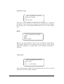
Spectrum Average
<SET PARAMETER MODE>
Spectrum Average
4
Enter a value
This value is the number of scans that are averaged for a spectrum
calculation. The more spectra averaged, the less the noise but the longer
the response time. Each spectrum adds about 0.25 sec to the response
time.
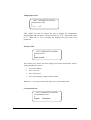
RCalb
<SET PARAMETER MODE>
RCalb
2345
Enter a value
RCalb is the gain calibration factor for the concentration measurement.
This number should not be changed from the factory setting unless
calibration equipment is available and a full calibration procedure is
followed.
Alarm Action
<SET PARAMETER MODE>
Alarm Action
0
0->0 1->Full Scale
This value determines whether the concentration value is set to zero or full
scale in the event of an alarm condition.
2001, SpectraSensors, Inc.
21
Zero Offset
<SET PARAMETER MODE>
Zero Offset
0
Enter a value
For concentration measurements it is necessary to compensate for small
amounts of background gas that adsorb some laser light, causing an offset
to be introduced into the measurements. This number should not be
changed from the factory setting unless calibration equipment is available
and a full calibration procedure is followed.
Logger Rate
<SET PARAMETER MODE>
Logger Rate (s)
4
Enter a value
For applications where an external data logger is used: Logger Rate
allows the operator to set the averaging time period used by the analyzer
to match the data logger rate. Longer periods results in "cleaner" data
because of the effects of the signal averaging. For example, if you are
logging data every minute, it does not make sense to have the analyzer
report the data every second because only one data point every 60 seconds
is being collected by the data logger. By changing the value entered for
the Logger Rate, the analyzer output can be matched to the data logger
sample rate, resulting in optimum signal averaging. The setting can vary
from 1 to 300 seconds.
Enter a numeric value (in seconds) and press the "*" key to accept the new
value. The system will cycle to the next adjustable parameter. If no
changes are desired to the Logger Rate, just press the "*" key.
2001, SpectraSensors, Inc.
22
Temperature Unit
<SET PARAMETER MODE>
Temperature Unit
0
0 ->C 1->F
This enables the user to choose the unit to display for temperature
measurement and dew point. Choose between °C or °F. The default value
is °C. When the "*" key is pressed, the display will cycle to the next
parameter.
Pressure Unit
<SET PARAMETER MODE>
Pressure Unit
0
Enter a value
This enables you to choose the unit to display for Pressure measurement. Choose
among the following choices:
•
Press 0 for millibar
•
Press 1 for Torr
•
Press 2 for Pascal
•
Press 4 for Pounds per Square Inch Absolute
When the “*” key is pressed the LCD will cycle to Concentration unit.
Concentration Unit
<SET PARAMETER MODE>
Concentration Unit
1
0:ppmv 1:lb/mmscf
2001, SpectraSensors, Inc.
23
This enables you to choose the unit to display for water concentration. For H2O
concentration display there are the following options:
•
Press 0 for ppmv
•
Press 1 for Lb/mmscf
This is the last parameter. Press # + 1 to return to Normal Measurement Mode.
Mode 3 (CO2 Measurement Parameter Change)
When CO2 is not being measured the Normal Mode will be displayed.
Mode 3 allows the operator to access and change parameters for CO2
measurements in the same manner as Mode 2 is used to alter the parameters for
the H2O channel. The menus for Mode 2 and Mode 3 are identical. The only
difference is the unit of measurement used when entering parameters.
For CO2 the Zero Offset and Span Limit parameters must be entered in percent,
while for H2O these values are entered in either ppmv (Zero Offset) or
lbs/MMscf (span limit). Follow the instructions for Mode 2. These numbers
should not be changed from the factory setting unless calibration equipment is
available and a full calibration procedure is followed.
Mode 4 (System Diagnostic Parameters for Water)
#
+
4
Mode 4 displays System Diagnostic Data for water. These values may be useful
when trouble shooting the system.
PP2F: 1536
POWER: 2854
INDEX:
280
ZERO:
-8
2001, SpectraSensors, Inc.
24
PP2F shows the value of the concentration signal is A/D counts. A normal range
is 0 to 6000 depending on the concentration of water present.
Power show the laser power detected at the absorption peak. Acceptable limits
are 1000 to 4000. A low number may indicate that the optics require cleaning.
Index is the position of the absorption peak within the wavelength scan. It
should normally be between 250 and 350.
Zero is the detector signal value when the laser is turned off. It should be in the
range of –40 to + 40.
Mode 5 (System Diagnostic Parameters for CO2)
+
#
5
Mode 5 displays the System Diagnostic Parameters for CO2. The description
and normal ranges are the same as for Mode 4.
Function Key
The Function Key F1 is reserved for factory and service personnel diagnostics. It
is not meant to be used by operators, although depression of this key will not
result in any affect on the device for the user.
Test Key
#
+
TEST
The TEST key provides basic diagnostic test results for laser power, pressure and
temperature sensors, and the infrared spectrum that is recorded by the system for
analysis. The LCD will display the following for a dual-channel system.
<TEST MODE>
ENTER SELECTION
1=H20 2=CO2
2001, SpectraSensors, Inc.
25
Select the entry for the channel you want to display. In the case of a single
channel system, this screen is not shown and one of the screens below will be
displayed instead.
To view the water channel press “1” and the LCD will display the following:
<H2O SYSTEM TEST>
LASER POWER: OK
P,T SENSORS: OK
SPECTR:OK
NULL:OK
To view the carbon dioxide channel press “2” and the LCD will display the
following:
<CO2 SYSTEM TEST>
LASER POWER: OK
P,T SENSORS: OK
SPECTR:OK
NULL:OK
If a failure is detected, the LCD will display “FAIL” for that component. If the
LCD displays a failure for one or more of the components, refer to the
troubleshooting section.
Mode 6 (Diagnostic Data Dump)
This mode is used to output to the serial ports the individual data points of both the DC and PP2F
spectra that are analyzed by the instrument to calculate the gas concentration. Viewing these data
can be helpful in diagnosing potential problem with the instrument. The data points, along with
intermediate calculation results, are output to the serial ports whenever mode 6 is selected. The
data for the H2O channel is output on the H2O serial port and the data for CO2 (in a two channel
unit) is output on the CO2 serial port. See page 15 of the Operators Manual for wiring and
protocol information for the serial ports.
Any computer terminal program that works with the RS-232 serial port can capture the serial port
data. The Hyperterminal program included with Microsoft Windows is a typical example of such
a program. Before entering Mode 6, the serial port should be connected to the computer being
used for monitoring the serial port and the output stream should be showing on the screen. The
number of seconds between each line of data output should be the Spectrum Average number set
in Mode 2 divided by 4. The factory default setting of Spectrum Average = 4 gives a line of
output each second. To save the data from the serial port, use the capture feature on the terminal
2001, SpectraSensors, Inc.
26
program. (For Hyperterminal, use the Transfer/Capture Text function and enter a file name to
identify the data to be captured.) Once capturing is taking place, enter mode six by pressing:
#
+
6
Mode 6 will display:
Dump Stats Mode …
Index: 0
The index will count by 50s from 0 to 511 in a few seconds and the screen will display:
MODE
Press 1 to return to normal operation.
When normal operation has resumed, stop the capture of the serial data. (For the Hyperterminal
program, press Transfer/Capture Text/Stop.) This file can be imported into a spreadsheet
program such as Excel and the data plotted.
At the end of the spectrum data, there is a section that displays the intermediate calculations.
This information can be valuable to the factory if troubleshooting is necessary.
Power-down Procedure
The power-down procedure is simple. Remove the power cable from the AC
outlet or disconnect power from the gas sensor circuit in the case of a hardwired
system. There is no specific sequence beyond that for shutting down 2000 Series
gas sensors.
If the unit is going to be shut down for some time, it is recommended that the
sampling gas line shut-off valve be turned off. Also, disconnect AC power to
prevent damage from lightning strikes.
2001, SpectraSensors, Inc.
27
Maintenance
The 2000 Series requires very little regularly scheduled maintenance. In fact, the
unit itself requires no maintenance that can be performed by the user. However,
there are some external conditions that can affect the measurement
Reducing Contamination of Gas Sampling Lines
Contamination in the gas sampling lines can contaminate the optics and
absorption cell causing problems. To keep the sampling lines clean and improve
response at very low humidity:
1. Make sure the coalescing filter is operating and replace if necessary.
Small amounts of glycol or amine in the gas phase should not cause
problems as they will be swept out of the sample region by the gas flow
and they do not affect the measurement in any way. But if liquid enters
the cell and accumulates on the internal optics the system will not
operate correctly. Pressure # + TEST on the keypad will indicate a
failure in laser power if the mirrors become contaminated.
2. Disconnect the gas sampling inlet and outlet lines from their respective
connections on the 2000 Series.
3. Wash the sampling lines with water or acetone and blow-dry with mild
pressure from a dry air or nitrogen source. It may be desirable to heat the
lines for a few minutes to clear residual water from the lines.
4. Reconnect the gas sampling lines by tightening the connection finger
tight and then tightening an additional ¾ turn with a 9/16-in. open-end
wrench.
Procedure for Cleaning Contaminated Mirrors
The 2000 Series is intended to measure very clean low water content gas (no
more than 20 lbs/MMscf). SpectraSensors has other models available that are
capable of measuring gas with higher moisture concentration. The sample gas
inlet line must have a coalescing filter to prevent contamination of the
internal optical components. Although the SpectraSensors Series 2000 gas
sensor can tolerate significant loss of reflectivity from its mirror, it may still be
necessary to clean the optics. Should gross contamination occur, such as in the
case of a filter failure, the optics may become severely contaminated and the
mirrors inside the sampling cells must be cleaned. If you cannot or do not desire
to clean the mirrors, your local representative can provide on-site service for a
small fee.
Note that if the gas sensor has become contaminated, the tubing and
instrumentation up stream of the sensor is likely to be contaminated as well. Be
sure to clean or replace these parts when the sensor is cleaned to prevent
recontamination of the sensor.
CAUTION! – It is extremely important that disassembly of the
measurement cell take place in a clean area so that dirt or other
2001, SpectraSensors, Inc.
28
contaminants do not get on the optical components during the cleaning
operation. In addition, the area should be well ventilated and personnel
should wear protective gear to prevent accidental contact with cleaning
solvent. Read the directions on the solvent before using.
Be careful not to touch any of the optical surfaces.
Do not use air from an air compressor to blow off the optics. It may contain
either liquid or solid contaminants and the high velocity of some nozzles may
propel dust into the mirror surface. Always remove power from the
equipment before cleaning.
Method:
SpectraSensors recommends using a solvent rinse cleaning process to avoid the
possibility of scratching the optics. In most cases this should be sufficient to
restore the optics to usable condition. A suitable cleaning kit is available from
your local sales representative. The kit includes mirror safe spray solvent, an
ultra pure air duster, lint free wipes, non-outgasing o-ring grease, hex wrench,
spare screws and washers, and spare fuses.
Process (see illustrations where shown for each step):
1. Mark the mirror flange and the end flange of the sample cell so that the
mirror can be reinstalled with the same rotation.
2. Remove the six screws holding the mirror assembly to the bottom of the
sample cell. Note the arrangement of the washers, lock washers, and
nuts so that the flange can be attached the same way on reassembly.
2001, SpectraSensors, Inc.
29
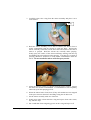
3. Carefully remove the o-ring from the mirror assembly and place it on a
clean surface.
O-ring
4. Hold the mirror assembly over a sink or bucket (test bucket first to
ensure compatibility with the solvent) to catch any drips. Position the
mirror vertically so that the solvent flows down the surface of the mirror
when it is sprayed. Hold the solvent can vertically while spraying.
Gently spray the surface of the mirror and flange starting from the top
and flushing the solvent down while spraying. Less than five seconds of
spraying should be sufficient to clean normal contamination from the
mirror. Do not touch the mirror with the spray nozzle.
5. Allow the solvent residue to evaporate from the mirror surface. Inspect
the mirror for residual contamination. If contamination is not completely
removed, repeat the spraying process.
6. When the mirror looks clean, blow off any solvent that has been trapped
in the space between the mirror and flange using the air duster can.
7. Set the mirror assembly aside in a clean area.
8. Gently spray some solvent onto the o-ring and wipe it clean with a clean,
dry, lint-free wipe.
9. Put a small dab of non-outgasing grease on the o-ring and wipe it off.
2001, SpectraSensors, Inc.
30
10. Replace the o-ring into the mirror assembly. Do not touch the mirror
with the o-ring.
11. Disconnect the measurement head cables from the top of the control box.
(One cable is for the optical head and the other, if applicable, is for the
temperature and pressure probes.)
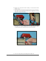
12. Remove the six screws holding the optical head assembly to the top of
the sample cell. Note the arrangement of the washers and lock washers
so that the flange can be attached the same way on reassembly.
13. Leave the o-ring in the top of the flange on the sample cell.
2001, SpectraSensors, Inc.
31
O-ring
14. Clean the window on the bottom of the optical head assembly using the
same procedure as for cleaning the mirror.
15. Position a bucket below the sample cell on the side of the electronics
box. Flush the inlet tube, outlet tube, and the inside walls of the sample
cell with the solvent, letting it drip down into the bucket.
16. After flushing for 5 to 10 seconds, blow off any residual solvent residue.
17. Re-attach the optical head assembly to the top of the sample cell.
18. Re-attach the mirror assembly to the bottom of the sample cell, aligning
it the same way it was to begin with.
19. Re-connect the measurement head cables.
20. The gas sensor is now ready to power up.
2001, SpectraSensors, Inc.
32
Troubleshooting
Gas Leaks
Probably the most common cause of erroneous measurements is outside air
leaking into the inlet sampling line. It is recommended the inlet lines be leaktested periodically, especially if the unit has been relocated or if the unit has been
replaced or returned to the factory for service and the sample lines have been
reconnected.
High Humidity
High humidity or condensation of water may cause temporarily high readings. If
the 2000 Series is exposed to these conditions for long periods of time, sampling
lines may take a long time to completely outgas. Sufficient time should be
allowed for the walls of the absorption cell to dry completely before the 2000
Series will return to making accurate measurements, especially when measuring
frost points below -70°C (-94°F).
Humidity levels higher than expected may be caused by leaks in the sample
system or tubing leading to the analyzer. All wetted parts should be of stainless
steel wherever possible. Materials such as vinyl, rubber, or PVC will
dramatically impair the measurement performance of the instrument and will
impact upon accuracy. Pressure regulators installed upstream of the analyzer
should be of high quality and fitted with stainless steel diaphragms.
Any hygroscopic material (dust) in the lines or absorption chamber can further
increase the time needed to return the measurements to normal levels.
Contamination and long exposure to high humidity are valid reasons for cleaning
the gas sampling lines periodically (as outlined above).
Excessive Sampling Gas Temperatures and Pressures
Errors can also arise from absorption cell temperature and pressure that exceed
the ranges allowed by the software. These ranges are 0.7 to 1.7 bar (10.3 to 25.0
PSI.) for pressure and –40 to +50°C (-40 to 122 °F) for temperature. Inlet
sampling gas temperatures and pressures must stay within these ranges in order
to obtain accurate measurements.
Electrical Noise
High levels of electrical noise can interfere with laser operation and cause it to
become unstable. The 2000 Series should never be operated with the front cover
open (see Warranty), and should always be connected to a properly grounded AC
power source.
NOTE: If the pressure and temperature readings (or any readings) on the
LCD are suspect, they should be checked against the specifications in the
Specifications Sheet in the Operations section of this manual.
2001, SpectraSensors, Inc.
33
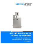
Further Undetectable Problems
If the above issues do not seem to be affecting a suspected problem with the
Series 2000 gas sensor, the user should consult the following final selftroubleshooting guide before contacting a sales representative for service.
Table 3 Final Troubleshooting Table
Symptom
Response
Non-Operation (at start up):
Is the AC power connected to both
2000 Series and AC power source?
Switch On?
Non-Operation (after start up):
Is the AC power source good? (100
to 250 VAC @ 50-60 Hz)
Check fuse.
Contact sales representative for
further troubleshooting.
Power Fail Error
Check optical head cable
connections. Do not disconnect or
reconnect any optical head cables
with the power connected.
Possible mirror contamination issue.
See maintenance section for
cleaning procedure.
If you cannot, or do not desire to
clean mirrors, contact sales
representative for service.
Spectrum Fail Error
Check
optical
head
cable
connections. Do not disconnect or
reconnect any optical head cables
with the power connected.
Contact sales representative.
P/T Fail Error
Check Pressure/Temperature cable
connections.
Contact sales representative.
Test button on keypad indicates a
failed component.
Contact sales representative.
LCD display does not update. Unit is
locked up.
Switch off AC power, wait for 30
seconds, then switch AC power
back on.
2001, SpectraSensors, Inc.
34
Warranty
The Manufacturer warrants the items delivered shall be free from defects (latent
and patent) in material and workmanship for a period of one year after delivery to
the Buyer. The Buyer’s sole and exclusive remedy under this warranty shall be
limited to repair or replacement. Defective goods must be returned to the
Manufacturer and/or its Distributor for valid warranty claims. This warranty shall
become inapplicable in instances where the items have been misused or
otherwise subjected to negligence by the Buyer.
Notwithstanding any other provision of this contract, no other warranties,
whether statutory or arising by operation of law, expressed or implied, including
but not limited to those of merchantability or fitness for particular purpose, shall
apply to the goods or services hereunder, other than the repair and replacement
warranty above. Seller shall in no event be liable to buyer or any third party for
any damage, injury or loss, including loss of use or any direct or indirect
incidental or consequential damages of any kind.
Disclaimer
SpectraSensors accepts no responsibility for consequential damages arising from
the use of this equipment. Liability is limited to replacement and/or repair of
defective components.
2001, SpectraSensors, Inc.
35