1
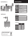
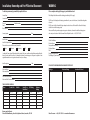
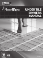
UNDER TILE
OWNERS
MANUAL
DISPOSAL
OF OBSOLETE
APPLIANCES
Please visit our website to ensure
you have the very latest version
of the installation instructions
Version 2.0
IMPORTANT NOTICE:
ENSURE THE MAINS SUPPLY IS ISOLATED PRIOR TO INSTALLATION/MAINTANENCE/TESTING
ALL VITREX FLOORWARM UNDERFLOOR HEATING MATS MUST BE EARTHED
A DEDICATED 30Ma (RCD) MUST BE USED WITH THIS HEATING SYSTEM
ELECTRICAL WORK WHICH IS SUBJECT TO PART P BUI LDING REGULATIONS MUST BE CARRIED OUT
BY A QUALIFIED ELECTRICAL CONTRACTOR
ALL WORK MUST CONFORM TO BS 7671.2008 AND THE LATEST IEE WIRING REGULATIONS
(CURRENTLY 17th EDITION)
CONSULT AN ELECTRICIAN PRIOR TO INSTALLATION TO ENSURE THE ROOM IS SUITABLE FOR
UNDERFLOOR HEATING SYSTEMS
Installation checklist
PLEASE:
DO Read all the instructions before commencing installation
DO Ensure a 30mA RCD is used in conjunction with the heating system
DO Test the system regularly during the installation process
DO Take care when planning the layout
DO Only cut the mat using scissors, do not use a knife
DO Ensure the cables are never less than 50mm apart
DO Take care when cutting the mat to prevent accidental damage to the heating cable
DO Wear gloves to prevent any irritation from the fibre glass matting
DO Ensure a qualified electrician completes the final wiring following the latest electrical regulations
DO Purchase slightly less than is required as the mats cannot be shortened in anyway
DO Only connect mats in parallel
DO Leave a 50mm gap between walls and the heating system
DO ensure the floor area is clean and free from any debris. Ensure no protruding nails heads etc.
DO use a multi meter to continually test the mat before and during the installation and before
laying final flooring
DO ensure all electrical connections conform to Part ‘P’ of the Building Regulations and latest IEE
Wiring Regulations
DO avoid any unnecessary traffic over the cables during installation
DO install thermal and sound insulation materials beneath the heating mats and ensure they are
suitable for use with Underfloor Heating systems.
Useful tools
PLEASE:
Do NOT Install the heating system under any fixtures or fittings i.e. bath tub, cabinets & toilets
Do NOT Place any heavy items on the matting (e.g. tiles) during the installation
Do NOT Cut the heating cable at ANY point
Do NOT Overlap the heating mats or cross cables at ANY point
Do NOT Install the heating system under any flooring other than tiles
Do NOT Leave any excess matting or cable – use a smaller mat if necessary
Do NOT Proceed without regular testing of the system
Do NOT Start up the system until the adhesive and grout is fully dry
Do NOT Connect mats in series
Do NOT place items which may prevent the heat rising onto the finish floor, such as heavy rugs,
bean bags and solid base furniture. This causes THERMAL BLOCKING and can damage the flooring
and heating system
Do NOT install the floor sensor close to other heat sources for example hot water pipes
Do NOT install the flooring without final continuity testing of the mats with a multi-meter
Room plan
Electrical Components:
Insulation Boards
Electrical backbox for thermostat if required
Mesh Joint Tape
Junction box if installing more than one mat
Floorwarm Thermostat
Conduit to house power cables
Residual Current Device 30 mA (RCD)
Marker Pen
Tape Measure
Scissors
Electrical screwdrivers & multi meter for connections
Gloves
Planning your layout
The mats can be adapted to suit all room shapes and layouts. If using more than one mat ensure
that the cold tails reach the thermostat. DO NOT cut the cable.
For difficult areas the mat can be cut away and the cable placed directly onto the insulation board
and secured into place using the glass fibre tape.
Connect the mat in parallel, ensuring cold tails reach the thermostat.
DIAGRAMS
Layout Example Diagrams
EXTENDING
ROTATING
Technical Specification
Layout Example Diagrams (cont.)
Turn
AWKWARD SHAPES
Typical Wiring System
Fused Spur
Power Supply
30mA RCD
F
u
s
e
Flip
TECHNICAL INFORMATION
Construction
Voltage
Maximum Load
Wire Thickness
Cable Flexibility
Power Range
Dual conductor wire with earth
Approved in
accordance with
EN60335 – 1:2004 / EN60335-2-96:2004,
EN50366:2003+A1:2006
230V ac – 50Hz
12W/m
Between 2.2m to 2.8mm
Minimum allowable cable radius is 16mm
150W to 750W
CONSTRUCTION
Thermal Conductor
Outer Insulation
IP Rating
Reinforcement Mesh
Fixing Materials
Thermostat
20°C
Junction
Box
Cold Cable Leads
2 x resistance wire insulated with FEP tested to 200°C
FEP tested to 200°C
IPX7
Fibreglass mesh
Supplied with 3 rows of double sided tape
Floor Sensor
POWER CONSUMPTION
Turn
Turn
DISPOSAL OF OBSOLETE APPLIANCES
DO NOT dispose of this appliance in your general waste. Your local
authority or retailer will be able to provide further guidance
1sqm
2sqm
3sqm
4sqm
5sqm
Amps per
Square Metre
Watts per
Square Metre
0.65
150
1.30
300
1.95
450
2.61
600
3.26
750
Surface Preparation
The floor must be clean and free from dust and dirt. Remove any old floor coverings.
Wooden Floors:
Ensure the floor has adequate ventilation underneath
Secure all floorboards to prevent flexing. A secure base is essential for tiled flooring so consider
reinforcing with WBP plywood, if necessary.
Concrete Floors:
Ensure floor is level and structurally sound
Testing your heating mat
We recommend testing the mat before fully un-wrapping. Test using a multi-meter to ensure
continuity through the cables.
Test regularly during the installation process and before laying the final flooring.
Insulation
We recommend the use of insulation boards prior to installing underfloor heating. Insulation
increases the performance and efficiency of running underfloor heating. Insulation also reduces
the heat up time and reduces running costs.
Instructions
•
•
Ensure the area is clean and free of any debris
Check the mats visually to ensure they are not damaged. Test the cable using a multi-meter,
compare the resistance rating to the following chart. Results should be within +10% / -5% of
the following readings:
Resistance (Ohm) for 230V 150W/m2
1 sqm 2 sqm 3 sqm 4 sqm
5 sqm •
Lay the insulation boards, we recommend a brick pattern layout. To cut the boards simply
run a knife through to score and flex. We recommend using a flexible powder tile adhesive and
floor adhesive trowel to install the insulation boards. Press firmly into place and once dry, tape
the edges of the board with Mesh Joint Tape.
353 Ohm
176 Ohm
118 Ohm
88 Ohm
71 Ohm
• Please take time to re-check your room plan ensuring that adequate space is allowed for any
additional fixtures and fittings to be installed post installation.
• Start to lay the mats on the floor, starting close to the thermostat. Mark out any cuts and turns. Mark the position where the temperature sensor is to be positioned.
• If you require a specific layout of cable not offered by the matting, simply cut the matting
away and fix the cable in place using the mesh tape. ENSURE THERE IS NEVER LESS THAN
50MM BETWEEN THE CABLES.
•
When confident everything is in the correct position, you are ready to install the floor sensor. Place the floor sensor underneath the mat - evenly spaced between 2 cables. Prepare a small
channel in the insulation board to house the floor sensor. Ensure the channel accommodates
the protective tube supplied. Place the floor sensor into the tube; tape over the end - this
stops the tile adhesive from coming into contact with the sensor. The tip of the sensor should
be at least 500mm away from the edge of the wall.
• Fix the mats to the floor using the 3 double sided tape strips (peel off adhesive backing). When cutting and turning the mats take care not to cut the cable.
• Once in place, it is good practice to test the resistance again using a multi meter.
• CONNECTION – This must be undertaken by a qualified electrician. This also validates your
warranty. Ask your electrician to sign and date your warranty card.
• Install the thermostat following the instructions supplied.
• As the power cable is thicker than the heating element it may be necessary to cut a channel
into the floor to ensure that you maintain an even level.
• Secure the power cables in place using tape.
• Run the power cables and temperature sensor cable to the thermostat using electrical
housing if necessary.
• It is possible to shorten or lengthen the cold power cables as necessary. This should only be
done by a qualified electrician.
• Test the system again using a multi meter. Write the meter readings on the warranty card to validate.
• Once laid, protect the cables with cardboard to prevent any accidental damage and avoid
any unnecessary traffic over the cables, whilst exposed.
Tiling
•
•
•
Use a flexible powder tile adhesive which is suitable for underfloor heating systems. Apply
following the manufacturer’s instructions taking care not to cause any damage to the
heating cables. We recommend the use of a plastic adhesive trowel for this purpose.
Ensure the cables are fully covered with an even layer of adhesive, taking care to avoid any
gaps or air pockets.
Ensure tiles are securely set into adhesive again avoiding any gaps or air pockets.
ADHESIVE AND GROUT MUST BE FULLY DRY BEFORE TURNING ON THE HEATING SYSTEM.
This can take a number of days depending on site conditions, temperature and weather.
THERMAL BLOCKS – caution must be taken to avoid thermal blocks.
Thermal blocks (increases in temperature at a localised point) are caused when an object placed
on the floor prevents the heat generated from being transferred into the air. Thermal blocks can
cause damage to the item and / or the flooring. Examples of items that can cause thermal blocks
are rubber backed rugs, solid based furniture, floor cushions / beanbags etc.
Room Layout Plan – use the grid below to plan your room
LIFETIME WARRANTY
Products covered by this warranty
Item No.
Description
Barcode
FWT001
FWT002
FWT003
FWT004
FWT005
Under Tile 1m2
Under Tile 2m2
Under Tile 3m2
Under Tile 4m2
Under Tile 5m2
5011204608218
5011204608225
5011204608232
5011204608249
5011204608256
Vitrex Floorwarm Underfloor Heating for TILE is covered by a warranty for the LIFETIME of the original floor covering under which it is
installed, subject to the terms and conditions set forth herein. The warranty is only applicable to the original purchaser and is not transferable.
This warranty is offered by QEP Co. UK Ltd.
During the period of this warranty we will replace free of charge or refund the cost of the product (at our discretion) or arrange for it to be
repaired. The cost of repair or replacement is the only remedy under this warranty. This warranty does not extend to costs incurred in relaying, replacing or repairing the floor covering or floor.
This warranty will only be valid if the purchaser promptly registers the product with QEP Co. UK Ltd. To validate the warranty please ensure:
• The product is registered with us within 30 days of purchase. Registration must be completed by filling out the warranty card supplied
in the Vitrex Floorwarm Underfloor Heating for TILE pack.
• In the event of a claim, proof of purchase is required so please ensure you retain your receipt or invoice.
• All final electrical connections must be carried out by a qualified electrician to the latest electrical regulations and comply with local
and national building regulations. The registered electrician must complete the resistance readings on the warranty card and sign it
stating their Part P Certificate Number.
• The heater must be earthed and protected by 30mA Residual Current Device at all times.
The warranty becomes invalid if:
• The floor covering installed above the heating mat is damaged, lifted, replaced, repaired or covered with subsequent layers of flooring.
• The heating mat is damaged during installation or by the laying of the floor covering.
As stated in the manual it is important to check the heating mat throughout the installation process and prior to laying the flooring.
Thermostats are warranted for a period of 3 years from the date of purchase, subject to the exclusions set out in this warranty document.
QEP Co. UK Ltd SHALL IN NO EVENT BE LIABLE FOR INCIDENTAL OR CONSEQUENTIAL DAMAGES, INCLUDING BUT
NOT LIMITED TO EXTRA UTILITY EXPENSES OR DAMAGES TO PROPERTY.
Ensure a copy of this room layout is displayed at the distribution box
Everest Road, Lytham St. Annes, Lancashire, FY8 3AZ, England Tel: +44 (0) 1253 789 180 www.vitrexfloorwarm.com
QEP Co. UK Ltd is not responsible for:
• Damage or repairs required as a result of faulty installation, incorrect application or misuse
• Damage caused by thermal blocking, details of which are explained in the Owner’s Manual
• Damage as a result of floods, fires, wind, lightning, accidents, corrosive atmosphere or other conditions beyond our control
• Use of components or accessories not compatible with this unit
• Products installed outside of the UK
• Regular maintenance, for example cleaning of thermostats
• Parts not supplied by QEP Co. UK Ltd
• Damage or repairs as a result of improper use, maintenance, operation or servicing
• Failures due to interruption or inadequate power supply
• Changes in the appearance of the product that does not affect its performance
• Any damage caused by frozen or broken water pipes in the event of equipment failure
Claims procedure:
Any claim made under this warranty should be made directly to QEP Co. UK Ltd. The claim should be made in a letter stating the following
information:
• Product purchased
• Place of purchase
• Date of purchase
• Details of the problem leading to the claim
• Proof of purchase
Please ensure a copy of everything sent is retained. This warranty is offered as an extra benefit and does not affect your statutory rights. The
warranty period commences from the date of purchase. Products must be registered within 30 days of purchase. Registration for warranty is
confirmed only when a letter of confirmation is sent by QEP Co. UK Ltd.
QEP Co. UK Ltd.
August 2010
Installation, Ownership and Part P Electrical Document
WARNING
To validate your warranty you must fully complete this form
Please complete and display this page at your distribution board
Owners Name
Owners address
Postcode
Telephone number Email
Date of purchase
Owners signature
Date Installers Name
Installers Telephone Number
Please state the room in which the heater(s) is installed:
Kitchen
Bathroom
Conservatory
Hall
Other
I confirm that I have read and fully understand the contents of the terms, conditions and installation manual and that the
heater(s) has been installed as directed. I confirm that the heater(s) was working prior to tiling and accept that no claim
against the manufacturer or its agents can be made for any loss or damage.
Installers signature
Date
Electricians Name
Electricians Address
This building is fitted with an underfloor heating system utilising 240V ac supply.
Do NOT pierce the flooring above the heating system with nails, screws or other fasteners. (See installation diagram for
reference.)
Do NOT expose the floor to thermal blocking or attempt to reduce the area of the heated floor. (Ensure the flooring is
suitable for use with the heating system.)
In the event of flooding or when carrying out any repairs or alterations, disconnect the underfloor heating system
and contact your electrician or Vitrex Floorwarm Technical Helpline for advice. + 44 (0) 1253 789 180.
Details of Installation:
Electricians Name:
Company Name and Address:
Telephone Number:
Date:
Room with Heating Installed:
Total Wattage of System Installed:
PLEASE LIST THE HEATING MAT INSTALLED AND THE TEST RESULTS
Mat Type
Resistance Rating
Electricians Phone Number
Electricians Part P Certificate Number
TABLE OF HEATERS INSTALLED
Room
Product Code
Batch No.
Under Tile or
Under Wood
RCD Rating
Resistance
Reading
Hall
FWT005
12345
Under Tile
30 ma
76.8 ohms
Return completed form to:
Vitrex FloorWarm Warranty, Everest Road, Lytham St. Annes, Lancashire, FY8 3AZ
Vitrex Floorwarm +44 (0) 1253 789180 www.vitrexfloorwarm.com
Insulaton Test Passed