1
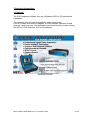
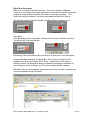
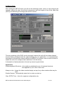
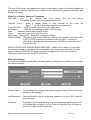
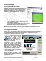
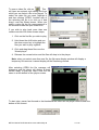
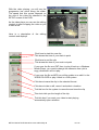
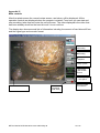
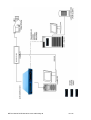
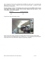
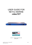
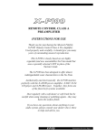
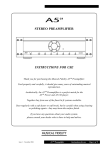
USER GUIDE FOR
NETmc MARINE
DVR Inspector System
Rev 4.10
February 2007
NETmc Marine DVRi Manual rev 4.1 February 2007
1 of 38
Contents
Section
1
2
2.1
2.2
3
3.1
3.2
3.3
3.4
3.4.1
3.4.2
4
5
Description
Introduction
System description
Hardware description and connections
Installation of Inspector with removable drive
Operating Instructions
Startup and main controls
The Set-up Page
Making a recording
Replaying the video
Using Windows Media Player™
Using the NETmc Marine “Viewer”
FAQS
Appendices
Appendix i – Technical specifications
Appendix ii – Definitions & Abbreviations
Appendix iii - Main controls
Appendix iv - Keyboard short cuts
Appendix v - COABIS interface
Appendix vi – Recording to a networked Server /
NAS
Appendix vii – mediaNET dispatcher settings
Appendix viii – Real time file duplication
Appendix ix – Example Coabis Interfacing
Diagrams
Appendix x – Integrated overlay configuration
Page
3
4
4
5
6
6
10
14
16
16
16
19
20
21
22
23
24
25
28
29
31
32
35
NETmc Marine
Dunann Cottage, Turfhill, Cuminestown Road
New Deer, Aberdeenshire
AB53 6TL
TEL. +44 1771 644001
FAX. +44 1771 644005
NETmc Marine DVRi Manual rev 4.1 February 2007
2 of 38
1 Introduction
NETmc Marine specialises in the design and manufacture of Digital Video
Solutions for the offshore market and has produced a range of digital video
acquisition systems ranging from single channel digital video recorders to
bespoke multi-channel systems for online data management and retrieval.
The entry-level recorder is the DVR-Inspector, a single channel digital video
recorder, designed to replace the standard VCR in offshore applications such
as ROV inspection surveys. The DVRi is built in to a 19” rack mountable
housing and accepts a variety of video inputs, storing the data directly on to a
hard drive, be this fixed internally, removable or an external drive connected
to the DVRi via Firewire or USB.
The DVRi can be supplied with MPEG1, MPEG2 or MPEG4 encoder boards.
Within each format the bit rate can be varied depending on the quality of the
video required.
In its basic operational mode the DVRi can simply be used as a replacement
for a VCR, it is easy to use and has a straightforward set-up screen and
recording controls.
However the DVRi can also be linked to a network so the video can be shared
with several people, or even controlled via a navigation package utilising the
NETmc Marine tool kit.
Digital video recording is set to become the industry standard for video
storage and the DVRi is set to become the industry standard DVR.
NETmc Marine DVRi Manual rev 4.1 February 2007
3 of 38
2 System Description
2.1 Hardware Description and Connections
The DVRi is a single channel rack mountable recorder running on a Windows
2000 platform. It is housed in 2U high casing and encompasses a removable
hard disk drive accessed via the front panel; other hard drive options are
available. All connections to the recorder are on the rear panel as shown
below, as is the on/off button for the internal power supply unit and the cooling
fan outlet. The power supply switch must be in the on (1) position for the
recorder to function; it is good practice, but not essential, to switch the internal
power supply off when the recorder is not in use.
On the front panel of the recorder is found the main ON button, the receptacle
(where fitted) for the removable drive and a small screen beside which there
are 4 black buttons, these buttons are for the control of the menus that are
displayed on the screen. These screens are primarily displaying status
indicators and so, under normal circumstances, the operator need not concern
themselves with them.
NETmc Marine DVRi Manual rev 4.1 February 2007
4 of 38
2.2 Installation of Inspector with removable drive
1. Install the DVRi in a 19” rack giving consideration to the height at which
the unit is mounted to facilitate the easy removal of the hard drive.
Note1: It is essential that sufficient space be allowed behind the
recorder to allow the power supply-cooling fan to function
correctly.
Note2: If networking the DVRi, all network connections must be made
and the network be live before switching on the DVRi,
otherwise no streaming video will be available.
2. If the video signal is first being routed via a composite monitor, ensure
the impedance switch on the monitor is set to open, otherwise no
picture will be seen on the DVRi screen.
3. Make all the necessary connections at the rear of the recorder,
including power cable, keyboard and mouse; the required connections
will vary depending on the video signal being input, display devices
being used etc.
4. Switch on power supply at rear of recorder, position 1.
5. Insert a hard drive in to the receptacle at the front of the machine. Do
this GENTLY. Although the drives are ‘Hot Swappable’ we advise that
drives are only inserted or removed when unit is powered OFF.
6. Press the “power on” button on the front panel. The two LEDs on the
front of the removable drives should be on. The Green LED is a power
indicator and the Red LED is a status indicator for the fan, if the Red
LED is on the fan is OK, if it is blinking then the fan is not working
correctly.
Note:
This is not a “power off” switch.
(To power down the recorder, use the normal Windows “shut down” procedure e.g. close all open windows, click on
start, select shut down and click OK. Windows and the recorder will now shut down correctly.)
NETmc Marine DVRi Manual rev 4.1 February 2007
5 of 38
3 Operating Instructions
3.1 Start-up
The DVR-Inspector software runs on a Windows 2000 or XP professional
installation.
The software suite will start automatically upon system boot.
If for any reason this does not happen, or if the software has been closed
down by a previous user, the application can be launched by double clicking
the NETmc, DVR-Inspector icon on the desktop:
Windows Desktop
NETmc Marine DVRi Manual rev 4.1 February 2007
6 of 38
On initial power-up, the software will display the message below.
Splash screen
NETmc Marine DVRi Manual rev 4.1 February 2007
7 of 38
Main Controls
All the operation controls are displayed when the program is started.
To familiarise you with them, they have been labelled overleaf:
Start
Recording
Stop
Recording
Take
Snapshot
Setup system
Signal type
and encode
format
Drive capacity
– free space
Video Window
NETmc Marine DVRi Manual rev 4.1 February 2007
Black Box
Recording
(ON /OFF)
Time encoded
this session
8 of 38
Black Box Recording
Black box recording is an optional extra. This option allows a separate,
continuous recording of the whole operation, for example for health and safety
purposes, independent of whether the video is currently recording. This
button will only be enabled if you have purchased the Black Box option.
The following images indicate whether the Black Box is enabled or not:
ENABLED
DISABLED
Recording
If the Black Box option is enabled, clicking on this button will start recording.
The button will now look like this:
Recording is also indicated by the presence of a green tick in the status bar:
Unless otherwise arranged, the Black Box will record to a separate 120
gigabyte hard disk drive called the D: Drive. Depending on the quality
settings chosen, the Black Box allows continuous recording for between 33
hours (highest quality settings) and 213 hours (lowest quality settings.)
Black Box files are automatically saved under the time and date recorded and
can be accessed through Windows.
NETmc Marine DVRi Manual rev 4.1 February 2007
9 of 38
3.2 Set-up Page
After clicking the SETUP button you will see the following screen. Here you can configure the
recorder; setting the video format and compression rate, the length or size of the video files
(PKTS) and allocating the storage path and file names.
The set-up settings of the DVRi can be changed, however the unit will have been shipped
from the factory configured with the optimal settings for your application– it is recommended
that these be left as shown above (settings for MPEG1) or at least a note is made of them to
enable the unit to be configured as it was when it left the factory.
A description of each parameter in the set-up screen is given below:
Application:
Enable keyboard Shortcuts – this enables or disables the use of keyboard shortcuts.
See appendix (iii) for a list of short cuts.
Always on top – keeps the video recorder display on top of any other windows that may be
open
Enable Preview – automatically starts the live video on start-up
Grey “SETUP” box – this is for engineer configuration only
NETmc Marine DVRi Manual rev4.05-coabis May 06
10 of 38
Format:
MPEG1 – Select to record in MPEG1 format
MPEG2 – Select to record in MPEG2 DVD format. This option is only available if there is a
suitable encoder installed
MPEG4 – Select to record in MPEG4. This option is only available if there is a suitable
encoder installed
NOTE: The selection of the format does not just depend on the quality of the video you want;
consideration should be given to how you will view the data at a later date. For instance
should you wish to view the data over the Internet then you may wish to use the lowest
compression rate available.
Source:
BNC –
Click this if video is coming in via the BNC connector on the rear panel i.e.
Composite input.
Y/C –
Click this if video is coming in via the Y/C connector on the rear panel
PAL –
Click here if input video is in the European format PAL
NTSC – Click here if input video is in the American / Asian format
Video Storage Format:
MPEG only – This setting will only record raw mpeg files
Pkt with embedded nav – With this option enabled, and a Navigation string being input to
the recorder, each MPEG file will be tagged with positioning data,
this then enables the video to be integrated in to a GIS system at
a later date.
Note: For ROV structural inspections there is no benefit to ticking
this box as generally there is no acoustic positioning data
available.
Device:
Enable Remote Access – Allows network control
Device Address – Required for network mode
Livestream Port – Allows other networked PCs to view video live. This option is switchable
as some networks might not be able to handle streaming video.
Quality:
Allows selection of bit rate – as specified in procedure or by experiment
Maximum Segment Size:
Each section of video recorded can be broken down into discreet video clips to aid reviewing
and managing the files. These sizes of each clip can be set by time or volume of data.
Should you wish to be able to download a file to a certain type of media e.g. a floppy disc,
then you would select file size as the controlling factor and set the size to fit your disc.
If on the other hand you wish to store the video by time then select that option and put in the
number of seconds you want the file to be.
NETmc Marine DVRi Manual rev4.05-coabis May 06
11 of 38
The size of file chosen will depend very much on the project in hand, but should probably be
no less than 5 minutes; otherwise the number of files recorded may become excessive and
difficult to manage.
Video File Location, Share and Templates:
Store Path – This is the location that your video files
The default location for the removable device is “D”.
Videofile
Prefix
will
be
stored.
-
Adds a chosen name or auto variable to the video file
Select “?” for list of auto name options – see appendix 2
Snap File Prefix – Adds a chosen name to the still image grab
Add Seqno –
Adds an incrementing number to the file name
Date –
Adds the current date to the file name
Time –
Adds the current time to the file name
Reset ssn=1, reset seq=0 – Reset auto increment numbers
SNAP FORMAT – The default stills format is Bitmap, however it is possible to record the stills
in GIF or JPEG format which makes smaller file sizes. To select an
alternative to Bitmap, click the radio button ‘OTHER’ and then select the
relevant tick box.
SHOW STATUS INFO SCREEN WHEN SNAPPING – When a still is taken you can make
the recorder indicate to you that a still is being taken, this momentarily interrupts the video
signal, however it DOES NOT stop the recorder recording video. If you do not want to
interrupt the onscreen video DO NOT tick the box.
Black Box Settings
If you have purchased the Black Box recording option, clicking this box enables you to modify
the relevant settings.
Storage Path -
Unless otherwise arranged, the default storage location is the d: drive and
should not be changed.
Job Reference -
This would ideally refer to the general operation (e.g. diver, ROV) and not
a specific task.
Password -
A password can be entered here to prevent accidental switching on or off
of the Black Box recording, or if the “Reqr for Stop Only” box is ticked, to
prevent accidental switching-off only.
NETmc Marine DVRi Manual rev4.05-coabis May 06
12 of 38
Options at bottom of Set-up Page
Apply – applies the changes
Reset – Undoes any changes you have made during the current visit to the
set-up screen
Close – Closes the SETUP window
Once the system has been configured click on the “CLOSE” button to return to the main
control screen where you can begin recording.
NETmc Marine DVRi Manual rev4.05-coabis May 06
13 of 38
3.3 Making a Recording
Once the system is running, the software will default to ready mode.
With no video signal, the preview screen will appear BLUE (as above)
With a signal applied, the video will appear in the preview window. (below)
To start the recording, simply press the RECORD button.
NETmc Marine DVRi Manual rev4.05-coabis May 06
14 of 38
When recording has started, the button will become depressed and the minute counter will
start to increment.
Once the desired footage has been recorded, simply press the STOP button to end
recording.
At any point during the recording or preview, the image on the screen can be saved as a
bitmap file by clicking the STILL button.
To resume logging, simply click the RECORD button again.
The system will automatically create a new file, automatically named as per the configuration
in the SETUP page.
NETmc Marine DVRi Manual rev4.05-coabis May 06
15 of 38
3.4 Replaying the data
3.4.1 Using Windows Media Player™
Assuming the video was recorded to a removable drive
you will need to insert the drive in to the USB caddie
and connect this to your PC. Once the storage unit is
connected to the USB port of your PC, you may be
asked to install a driver to allow the drive to be seen,
this is available on the CD supplied with the Caddie,
insert the CD provided in to your computers CD drawer
and follow the on screen instructions.
Once installed, the storage unit will appear as an
additional drive on “My Computer” or file explorer, once
installed –
• Go to the Desktop
• Click on “My computer”
• Click on the drive to which you are storing the video
• Open the video folder there
• Double click on the video file you wish to check; this will
automatically open up in Windows Media Player
NOTE: Using Windows Media Player it will only be possible to play one video file at a time.
3.4.2 Using the NETmc Player
Another way to view the video is with the NETmc Marine viewer. You will be provided with a
CD containing the NETmc viewer, insert this into your PC and follow the on screen
instructions (or manually click setup.exe) to install.
To use the special player, click
on the “3HEAD PLAYER
TOOL” short-cut. (This is
called the 3 head player as it
can be used with our 3
channel DVR PRO as well).
You now have access to a very powerful
viewer and editing software package
which can play multiple contiguous files
and edit across them using the “MARK IN”
and “MARK OUT” buttons. This edited
video can then be saved as a new file.
There is also the facility to take additional
“SNAPS” during review.
Across the top of the viewer is where
navigation data is displayed, if there is any
attached to the video.
NETmc Marine DVRi Manual rev4.05-coabis May 06
16 of 38
To open a video file, click on
This
will open an explorer style dialog box from
which you can select a file to be played. To
select the video file you want, highlight it
and then clicking “OPEN”. Another way of
the selecting the file is to click on it and
drag it over the 3Head viewer. When you
select a video file the file name appears in
the window beside the open folder icon.
If you wish to play back more than one
continuous video file follow theses steps;
1. Click on the first file you wish to play
2. Hold down the shift button and use
the down arrow key to highlight the
files you wish to play together.
3. Click and drag these files over the
3Head player.
4. Release the mouse button and the files will drop in to the player.
Note: when you select more than one file, the file name display window will display a
temporary file name as it cannot display all the files being viewed.
After selecting OPEN the file manager will
disappear and the player will display a black
screen ready to play the video, note the file
name in at the bottom of the player screen.
To start, stop, pause, fast forward or fast backward the video use the player controls near the
bottom of the screen.
NETmc Marine DVRi Manual rev4.05-coabis May 06
17 of 38
With the video playing, you will see the
progression bar move along the slider.
The speed that this moves depends on
the size of the video file selected in the
SETUP screen of the DVRi.
As the video plays you can use the editing
controls to start cropping the video or just
to take a still.
Here is a description of the editing
controls and displays
Click here to start the new clip
This shows the time of your mark in point
Click here to end the clip
This shows the time of your mark out point
If you save the file as a PKT then, to play it back on a Windows
Media Player, you need to change the extension from .pkt to
.mpg, otherwise it will not play.
If you save the file as MPG you will be unable to re-edit it in the
3HEAD PLAYER or play it back in a GIS system.
Click here to save the clip in the selected format.
Click here to take a still, name it and select a location.
Tick this box for the system to name the and store the clip
This clock tells you the length of the clip.
Tick this box if you want your video to start playing
automatically upon selection
NETmc Marine DVRi Manual rev4.05-coabis May 06
18 of 38
4
FAQs
Q. “When the system starts – there is no picture on the screen, just green noise”
A. This is because the camera is not outputting a signal.
Q. The screen is completely black.
A. Check that you have not selected MPEG2 on a box that only has MPEG1 encoder
installed.
Q. The viewing screen has reduced in size when I go to Windows and back again.
A. This is a Windows derived problem. Shut down the NETmc Marine application and relaunch.
Q. When I try to play back my video clips in Windows Media Player it does not play.
A. Check that the Extension to the file is mpg, if it is .pkt then change it to mpg.
NETmc Marine DVRi Manual rev4.05-coabis May 06
19 of 38
Section 5
APPENDICES
NETmc Marine DVRi Manual rev4.05-coabis May 06
20 of 38
Appendix i
Technical Specifications
Power Requirements
100 - 260 Vac, 50 - 60 Hz
Power Consumption
180w
Operating Temperature
10 - 35 Degrees
Non-operating Temperature
-10 - 60 Degrees
Operating Humidity
5-95% RH non-condensing
Non-operating Humidity
5-95% RH non-condensing
Operating Shock (read)
65G, 2ms
Non-operating Shock
250G, 2ms
Operating Altitude
-305m – 3,050m
Non-operating Altitude
-305m – 12.200m
Operating Vibration
Non-operating Vibration
Linear 20-300Hz, 0.75G (0 to peak)
Random 10-300 Hz, 0.004g2/Hz
Low frequency 5-20 Hz, 0.195 inches (double amplitude)
High frequency 10-300Hz, 5.0G (0 to peak)
Dimensions
482(W) x 88.5(H) x 455(D) (2U case)
Weight
15kg
Video Input
Composite (BNC) / S-VHS (4-way mini Din) PAL / NTSC
Video Stream Format
MPEG1 / MPEG2 / via codec MPEG4
Video Rate
500 kbps - 6 Mbps
Audio
Analog stereo line input
Network Support
10 / 100 Base T
Serial Ports
External Firewire / USB2 drives 9 Way D-Type for serial navigation
Storage and shipping
After overnight road freight the units should be left at room temperature for 24 hours before
powering on.
After air freighting the units should be left at room temperature for 48 hours before powering
on.
NETmc Marine DVRi Manual rev4.05-coabis May 06
21 of 38
Appendix ii
Definitions & Abbreviations
Definitions
DVRi
DVR Inspector Single Channel Digital Video Recorder
Abbreviations
ASCII
American Standard Code International Interchange
DB
Database
DLT
Digital Linear Tape
DRS
Digital Review Suite
DVR
Digital Video Recorder
HTML
Hyper Text Mark-up Language
MPG
Moving Pictures Expert Group File extension for a video file
MPEG1
Industrial recording format, controlled by the Moving pictures expert group
Playable on all Windows operating systems win95 ->
PKT
Packet File Extension
PAL
Phase Alternation by Line – the European video format
NTSC
National Television Standards Committee – American / Asian video format
JPEG
Joint Photographic Experts Group
Mbps
Mega bits per seconds – rate of video encoding
QC
Quality Control
USB
Universal Serial Bus
Store path Local on hard-disk where the video will be placed
SVHS
Super Video Home System
TIFF
Tagged Image File Format
NETmc Marine DVRi Manual rev4.05-coabis May 06
22 of 38
Appendix iii
Main controls
After the splash screen the normal review screen, see below, will be displayed. All the
operation controls are displayed when the program is started. From here you can start and
stop recording, take clips and enter the set-up screen. The video displayed is the video that
has been already stored on the hard drive so it is not real time
The display also shows several bits of information including the amount of hard drive still free
and the signal type and encoder format.
Start
Recording
Stop
Recording
Take
Snapshot
Setup system
Signal type
and encode
format
Drive capacity
– free space
Video Window
NETmc Marine DVRi Manual rev4.05-coabis May 06
Black Box
Recording
(ON /OFF)
Time encoded
this session
23 of 38
Appendix iv
Keyboard short cut
ShortCut Key
R
S
Spacebar
NETmc Marine DVRi Manual rev4.05-coabis May 06
Function
Record
Stop
Snap
24 of 38
Appendix v
COABIS Interfacing
This section explains how to configure the Coabis digital video interface for the NETmc
Marine DVR Inspector hardware. There are 2 parts to configuring the interface. First, you
must connect and detect the encoder. Secondly, you must define where routine and
anomalous video footage and still images are to be stored, and which applications are to be
used to display the clips and images.
Hardware setup
To command a DVRi from a Coabis system you will need:
A PC to run Coabis
A network card in that PC
An IP address on your coabis machine in the same range as the DVRi
A cross-over network cable (or hub/switch and 2 cables) to link PC & DVRi
Once you have Coabis installed on your PC – connect its network cable to the DVRi – either
via a cross-over cable, or by using a network hub/switch.
Set the IP address of the Coabis box to be in the same range as the DVRi.
Typically, DVRi units will have an IP of 192.168.1.serialno (i.e. serial number 37 will be
192.168.1.37) and a subnet mask of 255.255.255.0.
The coabis PC should have the same subnet and its IP address should start with 192.168.1.?
– with ? being anything which is not already in use on the network – and not the same as the
DVRi.
If your Coabis PC is also part of a corporate IT network – you may need to get a second
network card installed – alternatively you can configure the DVRi to join the corporate
network. Permission and settings must be granted by your IT manager - consult them or
NETmc Marine for more advice.
Configuring the Encoder
On the encoder, run the DVRi Setup shortcut. From the DVRi set-up screen, ensure the
following are set:
AddFileNo, AddSeqNo option MUST be checked.
Date: Both Date options MUST be unchecked.
Time: Both Time options MUST be unchecked.
The video output format and quality settings are at the discretion of the end-user.
NETmc Marine DVRi Manual rev4.05-coabis May 06
25 of 38
The coabis PC and the DVRi must be able to view the storage location for the digital video.
Therefore, if the video being stored to the DVR is internal or caddie drive – these must be
“shared” so others can see them over the network,
This is done by using the windows explorer on the DVRi and simply ‘right-clicking’ the drive
you wish to share. Select “Sharing” – enable sharing and enter a share name of your choice.
When setting up paths to this location within Coabis, use the UNC naming convention –
which is two back-slashes then the IP address of the unit with the share then back-slash the
share name. We recommend the share name is “Coabis” e.g.
\\192.168.1.37\coabis
Configuring Coabis
1. Connect the digital video encoder following the manufacturer’s instructions, and the
“Configuring the Encoder” instructions above.
2. Click Tools > Digital Video Setup from the Site module menu.
3. Enter data as follows:
Digital Video Encoder: Select Mnet from the drop-down list.
IP Address: Enter the IP address of the digital video encoder.
Digital Video Encoder Connected: If the encoder is already connected, this box is checked.
4. Click Test to check the connection. If the connection fails, check that the IP address has
been entered correctly, and that all the connections are securely attached.
Defining the Templates
All digital video footage and still image grabs must belong to a pre-defined Coabis template,
as defined in Baseline > Basics > Templates. The template codes are user-defined, but they
MUST be defined before the digital video interface will work. You need 2 template codes
covering: digital video and digital video still image grabs. For example:
DV: Digital Video
DVG: Digital Video Still Image Grabs
Add these templates in Baseline > Basics > Templates, with appropriate applications to
display the clips or images – e.g. Windows Media Player for clips.
Defining the Directories
You must also define where digital video files (both clips and still image grabs) are to be
stored. You will need 3 directories: routine digital video; anomalous digital video; digital video
still image grabs. (typically “routine”, “anoms” and “grabs”)
The location of the directories is user-defined. However, for routine digital video especially,
file sizes will be considerable (several gigabytes at least), so check that you have enough
space.
Define these directories in Baseline > Basics > Directories.
Video Set-up
On the Digital Video Set-up Video tab, enter data as follows
Template: From the drop-down list, choose the template code you defined for digital video.
Save Path Routine Video: From the drop-down list, select the directory code you defined for
routine digital video.
NETmc Marine DVRi Manual rev4.05-coabis May 06
26 of 38
Save Path Anomaly Video: From the drop-down list, select the directory code you defined for
anomalous digital video.
Grabs Set-up
On the Digital Video Set-up Grabs tab, enter data as follows
Grabs Template: From the drop-down list, choose the template code you defined for digital
video still image grabs.
Grabs Save Path: From the drop-down list, select the directory code you defined for digital
video still image grabs.
NETmc Marine DVRi Manual rev4.05-coabis May 06
27 of 38
Appendix vi
Recording to a networked Server / NAS
Sometimes, it may be more desirable to save digital video data to a central network available
storage facility – rather than storing the data locally on the DVRi (either on its internal disk or
on its caddie drive).
Examples of network storage can be
A NAS box
A server with storage attached or in built
Another PC on the network with a lot of storage
The setup procedure for this is:
On the network storage unit – create a shared directory where you want the video files to go.
This is typically named “Coabis”
It should contain the required 3 sub directories as defined in section v (typically “routine”,
“anoms” and “grabs”)
You then configure the Coabis PC to direct video and grabs to \\network_storage_IP\coabis
with the appropriate subfolder.
e.g. – if the IP of the NAS box or server is 192.168.1.1, you would enter into Coabis:
\\192.168.1.1\coabis\anoms
\\192.168.1.1\coabis\routine
\\192.168.1.1\coabis\grabs
Permissions
It is vital that the DVRi has permission to write to the NAS box or server.
The DVRi units ship with
User = Administrator
Pwd = (no password)
If the NAS or Server uses different credentials for its Administrator login, then there will be a
problem and no video files will be recorded. (You may get some .ssn files, but no .mpeg and
no .pkt files)
To solve this either:
- change the Administrator password on the NAS / server to blank
- or, change the logon settings of the mediaNET despatcher on the DVRi (see next
section)
NETmc Marine DVRi Manual rev4.05-coabis May 06
28 of 38
Appendix vii
mediaNET despatcher settings
To allow the DVRi to authenticate another server or storage device which does not have a
logon of “Administrator” which has no password – it may be necessary to change the
mediaNET despatcher settings on the DVRi.
On the DVRi unit – close the DVRI application – and go to the windows 2000 “Control Panel”.
From the “Administrative Tools” section, open “Services”
Scroll down the list unit you get to “mediaNET despatcher”
Right click on the mediaNET despatcher line and select “Properties”.
From the tabs – select “Log On”
NETmc Marine DVRi Manual rev4.05-coabis May 06
29 of 38
Select the use “This Account” option – and enter the account username and password
information which is authenticated to your remote storage device.
OK and accept these changes – and reboot the DVRi system.
This will now successfully log to the remote device.
NETmc Marine DVRi Manual rev4.05-coabis May 06
30 of 38
Appendix viii
Real time file duplication
If network connections are not reliable – or if a user wishes to save data to 2 different
locations simultaneously – it may be desirable to record video data to the local caddie drive
on the DVRi – and also to another location on the network.
mediaNET despatcher can only log to 1 location at a time – but using other 3rd party tools –
file synchronisation can be done between the DVRi and another storage device.
We can verify and confirm correct operation of these tools with our software and systems –
currently, the products we have tested and are happy with are:
Robocopy
If you use any other utility, we will not be able to support you – so take care in your selection
if you do not have IT support elsewhere.
Use of Robocopy:
You should download or be supplied a copy of Robocopy by our integrator.
Copy it to a directory on the DVRi (e.g. c:\robocopy)
Create a .cmd file and configure it to run in the “startup” folder of windows.
The contents of the .cmd file should be:
start " DV Sync" /min /low robocopy c:\video \\NAS_IP\backup /s /xo /m /mot:5 /mon:1 /tee
/np /log+:c:\coabis\sync_log.txt /xf sync_log.txt
*where c:\video is the path on the DVRi where the raw video is being initially saved and
\\NAS_IP\backup is the share on the remote system where the data is being replicated*
Robocopy.exe and sync.cmd can be downloaded from our website
www.netmcmarine.co.uk/file_downloads.htm
NETmc Marine DVRi Manual rev4.05-coabis May 06
31 of 38
Appendix ix
Example Coabis interfacing diagrams
NETmc Marine DVRi Manual rev4.05-coabis May 06
32 of 38
NETmc Marine DVRi Manual rev4.05-coabis May 06
33 of 38
NETmc Marine DVRi Manual rev4.05-coabis May 06
34 of 38
Appendix x
Integrated Overlay configuration
DVRi units can now be shipped with optional integrated overlay / screenwriter.
The overlay is internal to the DVRi – but its connections are presented externally – allowing
the user to by-pass if required.
To enable overlay – the input video signal should be first routed to “Overlay In” – and then
from ‘Overlay Out’ to the regular video input to the DVRi (using the supplied BNC to BNC
cable).
The overlay characters are generated by either using the overlay manager software from the
DVRi screen – or by injecting serial comments into one of the overlay serial ports on the
back of the DVRi.
Typically, this will be a cable to a Coabis, Scope or E-Inspect workstation on Serial 1 – while
Serial 2 might be reserved for CP or other information.
The cable used should be a 9way female to 9way female NULL modem cable.
When using Coabis – from Site. tools, video overlay:
Use Screenwriter
Baud = 9600
Parity = none
Databits = 9
Stopbits = 1
Com Port = port used on the coabis PC
NETmc Marine DVRi Manual rev4.05-coabis May 06
35 of 38
The internal overlay command structure follows the established industry standards – which
can be summarised as:
Function
Clear Screen
Cursor Right
Cursor Up
Cursor Down
Cursor Left
Home Cursor
Line Feed
Carriage return
Enable All Screens
Enable Screen 1
Enable Screen 2
Enable Screen 1 & 2
Enable Screen 3
Enable Screen 1 & 3
Enable Screen 2 & 3
Disable All Screens
Enable Time / Date
Top left
Bottom left
Top right
Bottom right
Hex Code
10
11
12
13
14
15
0A
0D
00
01
02
03
04
05
06
07
Dec Code
16
17
18
19
20
21
10
13
0
1
2
3
4
5
6
7
Key Code
^P
^Q
^R
^S
^T
^U
^J
^M
^@
^A
^B
^C
^D
^E
^F
^G
The overlay manager software will auto launch when the systems starts – and should be
minimized (by clicking mini mode) when not in use.
(a shortcut for overlay manager will be on the desktop if closed in error).
The software allows insertion of time / date and any text.
NETmc Marine DVRi Manual rev4.05-coabis May 06
36 of 38
Up to 4 pages of text can be configured and available for quick recall – by pressing the
appropriate screen number. Pages can also be saved and opened – allowing for preset
client specific configurations.
Overlay manager requires a link between the serial port of the DVRi and the chosen
serial input of the overlay. A short cable has been supplied with the system – but a
‘null modem’ cable will be suitable.
Serial port
2
3
5
Overlay Serial Input
3
2
5
A typical time, date and header overlay:
If the overlay text is jumpy, the genloc is having trouble syncing to the input video signal.
Check connections and signal levels (poor switchers etc). Line conditioning may be required
if the video source is a VCR as their output is not generally compliant.
NETmc Marine DVRi Manual rev4.05-coabis May 06
37 of 38
End of Document
NETmc Marine DVRi Manual rev4.05-coabis May 06
38 of 38