1
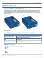
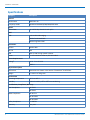
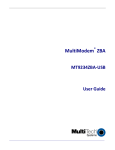
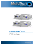
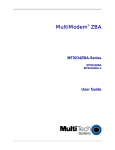
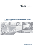
MultiConnect® Cell GPRS
MTC-G3 User Guide
MULTICONNECT®CELL USER GUIDE
MultiConnect®Cell User Guide
Model: MTC-G3
Part Number: S000579 1.0.2
Copyright
This publication may not be reproduced, in whole or in part, without the specific and express prior written permission signed by an executive officer of
Multi-Tech Systems, Inc. All rights reserved. Copyright © 2014 by Multi-Tech Systems, Inc.
Multi-Tech Systems, Inc. makes no representations or warranties, whether express, implied or by estoppels, with respect to the content, information,
material and recommendations herein and specifically disclaims any implied warranties of merchantability, fitness for any particular purpose and noninfringement.
Multi-Tech Systems, Inc. reserves the right to revise this publication and to make changes from time to time in the content hereof without obligation of
Multi-Tech Systems, Inc. to notify any person or organization of such revisions or changes.
Legal Notices
The Multi-Tech products are not designed, manufactured or intended for use, and should not be used, or sold or re-sold for use, in connection with
applications requiring fail-safe performance or in applications where the failure of the products would reasonably be expected to result in personal injury or
death, significant property damage, or serious physical or environmental damage. Examples of such use include life support machines or other life
preserving medical devices or systems, air traffic control or aircraft navigation or communications systems, control equipment for nuclear facilities, or
missile, nuclear, biological or chemical weapons or other military applications (“Restricted Applications”). Use of the products in such Restricted
Applications is at the user’s sole risk and liability.
MULTI-TECH DOES NOT WARRANT THAT THE TRANSMISSION OF DATA BY A PRODUCT OVER A CELLULAR COMMUNICATIONS NETWORK WILL BE
UNINTERRUPTED, TIMELY, SECURE OR ERROR FREE, NOR DOES MULTI-TECH WARRANT ANY CONNECTION OR ACCESSIBILITY TO ANY CELLULAR
COMMUNICATIONS NETWORK. MULTI-TECH WILL HAVE NO LIABILITY FOR ANY LOSSES, DAMAGES, OBLIGATIONS, PENALTIES, DEFICIENCIES, LIABILITIES,
COSTS OR EXPENSES (INCLUDING WITHOUT LIMITATION REASONABLE ATTORNEYS FEES) RELATED TO TEMPORARY INABILITY TO ACCESS A CELLULAR
COMMUNICATIONS NETWORK USING THE PRODUCTS.
Contacting Multi-Tech
Knowledge Base
The Knowledge Base provides immediate access to support information and resolutions for all Multi-Tech products. Visit http://www.multitech.com/kb.go.
Support Portal
To create an account and submit a support case directly to our technical support team, visit: https://support.multitech.com.
Support
Business Hours: M-F, 9am to 5pm CT
Country
By Email
By Phone
Europe, Middle East, Africa:
[email protected]
+(44) 118 959 7774
U.S., Canada, all others:
[email protected]
(800) 972-2439 or (763) 717-5863
Warranty
To read the warranty statement for your product, visit www.multitech.com/warranty.go. For other warranty options, visit www.multitech.com/es.go.
World Headquarters
Multi-Tech Systems, Inc.
2205 Woodale Drive, Mounds View, MN 55112
Phone: (800) 328-9717 or (763) 785-3500
Fax (763) 785-9874
2
MultiConnect® Cell GPRS MTC-G3 User Guide
CONTENTS
Contents
Product Overview .................................................................................................................................................... 5
About the MultiConnect Cell Modem........................................................................................................................... 5
Documentation ........................................................................................................................................................... 5
Descriptions of LEDs...................................................................................................................................................... 5
Side Panels .................................................................................................................................................................... 7
Specifications ................................................................................................................................................................ 8
Power Draw MTC-G3 .................................................................................................................................................... 9
Dimensions.................................................................................................................................................................. 10
Serial ......................................................................................................................................................................... 10
USB............................................................................................................................................................................ 11
Installing a SIM Card ................................................................................................................................................... 12
Removing a SIM Card................................................................................................................................................ 12
Installing and Using the Device .............................................................................................................................. 13
Installing the Device.................................................................................................................................................... 13
Placing Serial Devices in Power Save Mode.............................................................................................................. 13
USB Cable Recommendations................................................................................................................................... 14
Mounting Device to Flat Surface................................................................................................................................. 14
Antenna and Activation Information...................................................................................................................... 15
Antenna....................................................................................................................................................................... 15
Antenna Information................................................................................................................................................... 15
Antenna Requirements/Specifications ..................................................................................................................... 15
Antenna System Cellular Devices................................................................................................................................ 15
Account Activation for Cellular Devices ..................................................................................................................... 15
Device Phone Number ................................................................................................................................................ 16
Using Linux ............................................................................................................................................................ 17
Shell Commands.......................................................................................................................................................... 17
Testing Serial Ports.................................................................................................................................................... 17
Create a PPP Connection ............................................................................................................................................ 17
Example..................................................................................................................................................................... 17
Configuring and Communicating with Your Device................................................................................................. 19
Interacting with Your Device Overview ...................................................................................................................... 19
Before You Begin......................................................................................................................................................... 19
Using Command Mode and Online Data Mode.......................................................................................................... 19
Verifying Signal Strength............................................................................................................................................. 20
Example .................................................................................................................................................................... 21
Checking Network Registration................................................................................................................................... 21
Sending and Receiving Data........................................................................................................................................ 21
MultiConnect® Cell GPRS MTC-G3 User Guide
3
CONTENTS
Connecting Device to TCP Server as TCP Client ........................................................................................................ 21
Configuring Device as UDP Listener to Accept UDP Client Connections ................................................................. 22
Configuring Device as UDP Client to Connect to UDP Server ................................................................................... 23
Configuring Device as UDP Listener to Accept UDP Client Connections ................................................................. 24
Transferring FTP File to FTP Server ........................................................................................................................... 25
Downloading File from FTP Server............................................................................................................................ 26
Reading, Writing and Deleting Messages ................................................................................................................... 27
Reading Text Messages............................................................................................................................................. 27
Sending Text Messages ............................................................................................................................................. 27
Deleting Messages .................................................................................................................................................... 28
Regulatory Information.......................................................................................................................................... 29
EMC, Safety, and R&TTE Directive Compliance ......................................................................................................... 29
Restriction of the Use of Hazardous Substances (RoHS) ............................................................................................ 30
REACH Statement ....................................................................................................................................................... 31
Registration of Substances........................................................................................................................................ 31
Substances of Very High Concern (SVHC) ................................................................................................................ 31
Waste Electrical and Electronic Equipment Statement .............................................................................................. 31
WEEE Directive.......................................................................................................................................................... 31
Instructions for Disposal of WEEE by Users in the European Union ........................................................................ 31
Information on HS/TS Substances According to Chinese Standards ......................................................................... 32
Information on HS/TS Substances According to Chinese Standards (in Chinese) ...................................................... 33
4
MultiConnect® Cell GPRS MTC-G3 User Guide
PRODUCT OVERVIEW
Product Overview
About the MultiConnect Cell Modem
The MultiConnect® Cell MTC-G3 modems are ready-to-deploy, standalone quad-band GSM/GPRS modems that
provide wireless data communication. The modems integrate seamlessly with virtually any application, and are
useful for automated applications, such as remote diagnostics and remote monitoring. They are available with RS232 or USB connectors.
Serial
USB
Documentation
The following documentation is available on the Multi-Tech Installation Resources website at
www.multitech.com/setup/product.go.
Document
Description
MultiConnect Cell User Guide
This document. Provides an overview, safety and regulatory information,
schematics, and general device information.
GPRS AT Commands Reference
Guide
Configure the MTC-G3 with GPRS G3 AT Commands Reference Guide (part
number S000546).
USB Driver Installation Guide for H5 Provides instructions for installing USB drivers on Linux and Windows systems
and G3 Devices
(part number S000553).
Descriptions of LEDs
Devices that have a serial connector have the following LEDs:
■ Power
■ TR
■ CD
■ LS
■ Signal
MultiConnect® Cell GPRS MTC-G3 User Guide
5
PRODUCT OVERVIEW
Devices that have a USB connector have the following LEDs:
■ Power
■ LS
■ Signal
Note: All LEDs light for about 10 seconds when the device is powered up.
The tables that follow provide details about what the LEDs indicate.
Power
Not lit
DC power not present.
Lit
DC power present.
TR (Terminal Ready)
Not Lit
Data is not being transmitted.
Lit
Blinks when data is being transmitted.
CD (Carrier Detect)
Not lit
Data connection is not established.
Lit
Data connection is established.
LS (Link Status)
Not lit
There is no power to the cellular radio.
Continuously
lit
Powered and connected, but not transmitting or receiving.
Slow blink
Powered and searching for a connection.
Fast blink
Transmitting or receiving.Also appears if SIM is not installed.
Signal
6
ALL OFF
There is no power to the cellular radio.
Bar 1 ON
Very weak signal (7 < = RSSI <14).
Bar 1 and 2 ON
Weak signal (15 < = RSSI <23).
Bar 1, 2, 3 ON
Good signal (24 <= RSSI > = 31).
MultiConnect® Cell GPRS MTC-G3 User Guide
PRODUCT OVERVIEW
Side Panels
The device has connectors on either side. The figures that follow show the side panels.
Serial
USB
Note: The power-saving switch—which appears with the NORMAL and LOW POWER labels—is included
only on models that have a serial connector.
MultiConnect® Cell GPRS MTC-G3 User Guide
7
PRODUCT OVERVIEW
Specifications
Category
Description
General
Performance
GPRS Class 10
Frequency Bands
Quad-band EGSM 850/900/1800/1950 MHz
Speed
Packet Data
Up to 85.6 Kbps downlink and uplink
SMS
SMS
Point-to-Point Messaging
Mobile-Terminated SMS
Mobile-Originated SMS
Connectors
Cellular
Female SMA
RS-232
DE9
USB
Mini-B, USB 2.0 high speed or better
Power
2.5 mm miniature screw-on, RS-232 models
Power Requirements
Voltage1
Serial: 7 V to 32 V DC
USB 5 V
Physical Description
Dimensions
Dimensions are shown in the section “Dimensions” that follows.
Weight
8.2 ounces or 230 grams
Environment
Operating Temperature
-40° C to +85° C
Humidity
Relative humidity 15% to 93% non-condensing
Certifications, Compliance, Warranty
EMC Compliance
EN 55022
EN 55024
Radio Compliance
EN 301 511
EN 301 489-1
EN 301 489-7
8
Safety Compliance
IEC 60950-1
Warranty
Two years
MultiConnect® Cell GPRS MTC-G3 User Guide
PRODUCT OVERVIEW
1
Optional power must be UL Listed ITE power supply marked LPS or Class 2 rated 7 to 32 V dc, 0.5 A . Certification
does not apply or extend to voltages outside certified range, and has not been evaluated by UL for operating
voltages beyond tested range.
Power Draw MTC-G3
USB
5 volts
Cellular call box
connection no data
(amps)
Average measured
current (amps) at
maximum power
TX Pulse (AVG)
Amplitude Current
(amps)
Total inrush charge
measured in
MilliCoulombs (mC)
GSM850Mhz
0.040
0.238
1.14
18.56
Serial
Sleep Mode
Current (amps)
Cellular call box
connection no
data (amps))
Average
TX Pulse (AVG)
measured current Amplitude
(amps) at
Current (amps)
maximum power
Total inrush
charge measured
in MilliCoulombs
(mC)
0.015
0.041
0.167
0.887
0.770
0.012
0.034
0.132
0.662
0.836
0.005
0.017
0.056
0.218
0.773
7 volts
GSM850Mhz
9 volts
GSM850Mhz
32 volts
GSM850Mhz
MultiConnect® Cell GPRS MTC-G3 User Guide
9
PRODUCT OVERVIEW
Dimensions
Serial
10
MultiConnect® Cell GPRS MTC-G3 User Guide
PRODUCT OVERVIEW
USB
MultiConnect® Cell GPRS MTC-G3 User Guide
11
PRODUCT OVERVIEW
Installing a SIM Card
This model requires a SIM card, which is supplied by your service provider. To install the SIM card:
1.
2.
Locate the SIM card slot on the side of the modem. The slot is labeled SIM.
Slide the SIM card into the SIM card slot with the contact side facing down as shown When the SIM card
is installed, it locks into place.
Removing a SIM Card
To remove the SIM card:
■ Push the SIM card in. It ejects itself from the device.
12
MultiConnect® Cell GPRS MTC-G3 User Guide
INSTALLING AND USING THE DEVICE
Installing and Using the Device
Installing the Device
1.
2.
3.
4.
Connect a suitable antenna to the antenna connector.
If you are using the serial version of this device:
Connect the DE9 connector (9-pin) of the RS-232 cable to the RS-232 connector on the device, then
connect the other end to the serial port on the other desired device.
Screw-on the power lead from the power supply module into the power connection on the device.
Plug the power supply into your power source.
If you are using the USB version of this device:
For information about the USB cable that helps power your device, see the section "USB Cable
Recommendations."
The USB cable uses power from the USB power line. Connect one end of the USB cable to your computer
or other USB high power device, such as a hub.
Connect the other end to the device's USB connector.
The POWER LED lights after the device powers up.
Placing Serial Devices in Power Save Mode
You can place devices that have a serial connector in low power mode. When the device is in low power
mode—which is also sometimes called sleep mode or power save mode—the device's radio is operating with little
power. A power save switch on the device determines if the device's radio can operate in normal or low power
mode.
You might want your device to go into low power mode if batteries are used to power the device. For example,
you might want to use your device outdoors, and have it powered by a solar charged battery. By using low power,
you can save time and money by not having to replace batteries on devices operating in the field.
You can use many techniques to place the device into low power (sleep) mode. This example uses data terminal
ready (DTR) and the AT command +CFUN=5. For other techniques, review the AT command guide for your device,
as described in the Documentation topic in this guide.
You can make the device "wake up" from sleep mode by using the wake-on-ring feature: In the example that
follows, the ring indicator line wakes the host processor when the radio receives an incoming call or SMS message.
Your application then needs to act on the ring indication and wake up the device by asserting DTR.
Using Low Power Mode
To set up the device so it can be placed into low power mode:
1.
2.
3.
4.
Set the power-save switch to LOW.
On the RS-232 interface, ensure your application controls DTR and makes it active (on). To configure the
device for DTR control, issue either AT&D1 or AT&D2 for DTR control. The &D0 command does not allow
low power to operate.
To configure the device to enter low power (sleep) mode, issue AT+CFUN=5 to the radio.
To configure the device to wake from low power mode by using the wake-on-ring feature, issue
AT#E2SMSRI=1000. This configures the ring indicator to go active for 1000 ms when an SMS message is
received.
MultiConnect® Cell GPRS MTC-G3 User Guide
13
INSTALLING AND USING THE DEVICE
5.
To have the device enter sleep mode, set DTR to inactive (off) on the RS-232 interface. The clear to send
(CTS) signal is off when the device is in sleep mode.
USB Cable Recommendations
If your device has a USB connector, to avoid enumeration or power issues:
■ Use a high speed USB cable that is as short as possible.
■ Use a well shielded cable with at least 24 AWG wire pair for power/ground and 28 AWG wire pair for data
lines.
■ If possible, use a USB port that connects directly to the motherboard rather than a USB port with added
cabling inside the computer chassis.
■ Use USB 3.0 ports if available. These ports are typically rated for more current.
■ You can re-order the USB cable through Multi-Tech. The part number is CA-USB-A-MINI-B-3
Mounting Device to Flat Surface
1.
2.
3.
14
Locate the groove on the bottom of the device.
Slide the mounting rod through the groove.
To secure the rod to the desired surface, place and tighten two screws in the holes on either end of the
mounting rod. The dimensions illustration in this guide shows the mounting rod, as well as the
dimensions for placement of the screws.
MultiConnect® Cell GPRS MTC-G3 User Guide
ANTENNA AND ACTIVATION INFORMATION
Antenna and Activation Information
Antenna
The antenna intended for use with this unit meets the requirements for mobile operating configurations and for
fixed mounted operations, as defined in 2.1091 and 1.1307 of the FCC rules for satisfying RF exposure compliance.
If an alternate antenna is used, consult user documentation for required antenna specifications.
Antenna Information
This device was approved with the following antenna:
Manufacturer:
San Jose
Description:
Penta band antenna
Model Number:
EEN-502
Multi-Tech Part Number:
45009780L
Multi-Tech ordering information:
Model
Quantity
ANPB2-1HRA
1
ANPB2-10HRA
10
ANPB2-50HRA
50
Antenna Requirements/Specifications
Frequency range
824-960/1710-2170MHz
Impedance
50 ohm
VSWR
<2.5:1
Radiation
Omni directional
Polarization
Linear horizontal
Antenna System Cellular Devices
The cellular/wireless performance depends on the implementation and antenna design. The integration of the
antenna system into the product is a critical part of the design process; therefore, it is essential to consider it early
so the performance is not compromised. If changes are made to the device's certified antenna system, then
recertification will be required by specific network carriers.
Account Activation for Cellular Devices
Some Multi-Tech cellular modems are pre-configured to operate on a specific cellular network. Before you can use
the modem, you must set up a cellular data account with your service provider. Each service provider has its own
process for adding devices to their network. Refer to Multi-Tech's Cellular Activation site
MultiConnect® Cell GPRS MTC-G3 User Guide
15
ANTENNA AND ACTIVATION INFORMATION
http://www.multitech.com/activation.go for step-by-step instructions on activating your cellular modem with your
service provider.
Device Phone Number
Every device has a unique phone number. Your service provider supplies a phone number when you activate your
account, or if your device has a SIM card, the phone number may be on it. Wireless service provider
implementation may vary. Consult with your service provider to get the phone number for your device.
16
MultiConnect® Cell GPRS MTC-G3 User Guide
USING LINUX
Using Linux
Shell Commands
Testing Serial Ports
To test the serial ports created by the driver, type in a shell:
Note: Sending ATE0 is required, to avoid issues in the terminal output. It prevents the sending/receiving
spurious characters to/from the modem when used with the Linux commands “echo” and “cat”
Create a PPP Connection
Most recent Linux distributions have GUI tools for creating PPP connections; the following instructions are for
creating a PPP connection through command line interface.
PPP support must be compiled into the kernel; pppd and chat programs are also required.
pppd needs two scripts: the first script performs the environment setting and calls the second script, which is used
by the chat program. For creating a PPP connection type:
# pppd file /etc/pppd_script &
Example
# Debug info from pppd
debug
#kdebug 4
# Most phones don't reply to LCP echos
lcp-echo-failure 3
lcp-echo-interval 3
# Keep pppd attached to the terminal
# Comment this to get daemon mode pppd
nodetach
# The chat script (be sure to edit that file, too!)
connect "/usr/sbin/chat -v -f /etc/chatscripts/gprs_connect"
# Serial Device to which the modem is connected
/dev/ttyACM
# Serial port line speed
115200
dump
# The phone is not required to authenticate
#noauth
user <insert here the correct username for authentication>
name <insert here the name of the connection>
password <insert here the correct password for authentication>
# If you want to use the GPRS link as your gateway
defaultroute
# pppd must not propose any IP address to the peer
#noipdefault
ipcp-accept-local
MultiConnect® Cell GPRS MTC-G3 User Guide
17
USING LINUX
ipcp-accept-remote
# Keep modem up even if connection fails
#persist
# Hardware flow control
crtscts
# Ask the peer for up to 2 DNS server addresses
usepeerdns
# No ppp compression
novj
nobsdcomp
novjccomp
nopcomp
noaccomp
# For sanity, keep a lock on the serial line
lock
# Show password in debug messages
show-password
This script calls the option connect using the script gprs_connect, for example: After launching a PPP connection is
possible to use ftp protocol or other utilities that allow the access to the Internet.
18
MultiConnect® Cell GPRS MTC-G3 User Guide
CONFIGURING AND COMMUNICATING WITH YOUR DEVICE
Configuring and Communicating with Your Device
Interacting with Your Device Overview
This section describes how to use AT commands to interact with your device. Using terminal software such as
Kermit, you can issue AT commands to communicate with and configure your modem. The AT commands let you
establish, read and modify device parameters and help you control how the device operates. This section
documents basic interactions with your device, such as verifying signal strength and network registrations, sending
and reading SMS text messages, and sending and receiving data.
Your device supports Windows and Linux operating systems. If you use Windows, download and install the USB
drivers. See Installing Drivers for details. If you use Linux, your device is CDC-ACM compliant. Linux since version
2.6.28 has included CDC-ACM drivers, so additional drivers are not needed. See Using Linux for getting started with
Linux.
Generally, USB modems are used as unintelligent bit pipes. In Windows, this means you create a dial-up network
connection that uses the Windows IP stack to use the modem to create a PPP connection to the cellular network.
The modem is assigned an IP address from the cellular carrier. This connection provides Internet access and is the
basis for TCP/IP communication for sending and receiving email, creating TCP/UDP Sockets, or putting and getting
files from an FTP server.
In Linux, PPPD is used to dial the modem and create the connection to the cellular TCP/IP network. This provides
Internet access for sending and receiving email, creating TCP/UDP Sockets, or putting and getting files from an FTP
server.
Before You Begin
Before you begin:
■ Power up your device and ensure it is connected to the computer that you use to issue AT commands.
■ Install terminal software that can communicate with the device, such as HyperTerminal, TerraTerm, Kermit,
or Putty.
Using Command Mode and Online Data Mode
Modems have two operation modes, command and online data. When you power up the modem it is in command
mode and ready to accept AT commands.
Use AT commands to communicate with and configure your modem. They allow you to establish, read, and modify
device parameters and control how the modem works. The device can also generate responses to AT commands
that help determine the modem’s current state.
If the modem is in online data mode, it only accepts the Escape command (+++).
To send the modem AT Commands from terminal emulation software, set the software to match the modem’s
default data format, which is:
■ Speed: 115,200 bps
■ Data bits: 8
■ Parity: none
■ Stop bit: 1
MultiConnect® Cell GPRS MTC-G3 User Guide
19
CONFIGURING AND COMMUNICATING WITH YOUR DEVICE
■ Flow control: hardware
To confirm you are communicating with the device:
■ Type AT and press Enter.
If the device responds with OK, you are communicating with the device.
Verifying Signal Strength
To verify the device signal strength, enter:
AT+CSQ
The command indicates signal quality, in the form:
+CSQ: <rssi>,<ber>
Where:
<rssi>
Received signal strength indication.
0
(-113) dBm or less
1
(-111) dBm
2-30
(-109) dBm - (-53) dBm / 2 dBm per step
31
(-51) dBm or greater
99
Not known or not detectable
<ber>
Bit error rate, in percent
0
Less than 0.2%
1
0.2% to 0.4%
2
0.4% to 0.8%
3
0.8% to 1.6%
4
1.6% to 3.2%
5
3.2% to 6.4%
6
6.4% to 12.8%
7
More than 12.8%
99
Not known or not detectable
Note: Signal strength of 10 or higher is needed for successful packet data sessions.
20
MultiConnect® Cell GPRS MTC-G3 User Guide
CONFIGURING AND COMMUNICATING WITH YOUR DEVICE
Example
A example response to AT+CSQ:
+CSQ: 15,1
Checking Network Registration
Before establishing a packet data connection, verify the is device registered on the network. To do this enter the
network registration report read command:
AT+CREG?
If the device returns:
+CREG: 0,1
The device is registered.
If the device returns:
+CREG: 0,2
The device is in a network searching state.
Sending and Receiving Data
Connecting Device to TCP Server as TCP Client
To send data through a connect socket:
1.
2.
Define PDP Content (APN for SIM)
Enter
AT+CGDCONT=1,"IP","XXX.APN.com" where XXX.APN.com is the APN your cellular provider assigned to
your SIM card.
The device responds with OK
Bring up Data Connection Using Internal IP stack
Enter:
AT#SGACT=1,1
The device responds with the IP Address the cellular provider assigned to the device on connection,
followed by OK. For example:
#SGACT: 25.194.185.116
OK
Closing the Socket and the Connection
To close the socket:
■ Enter the escape sequence:+++
■ To close Socket 1, enter: AT#SH=1
The device responds with OK.
MultiConnect® Cell GPRS MTC-G3 User Guide
21
CONFIGURING AND COMMUNICATING WITH YOUR DEVICE
To close the data connection:
■ Enter: AT#SGACT=1,0
The device responds with OK.
Configuring Device as UDP Listener to Accept UDP Client Connections
To configure the device as a UDP client:
1.
2.
3.
4.
5.
6.
7.
8.
Check signal strength.
Enter:
AT+CSQ
If using a SIM card, configure the APN.
Enter:
AT+CGDCONT=1,"IP","XXX.APN.com" where XXX.APN.com is the APN your cellular provider assigned to
your SIM card.
Verify device is registered on the cellular network.
Enter:
AT+CREG?
Configure socket parameters
Enter:
AT#SCFG=1,1,300,240,600,50
Activate context one
Enter:
AT#SGACT=1,1
Set firewall rule to accept connections:
AT#FRWL=1,"###.##.###.#","###.##.###.#" where ###.##.###.# represents the IP range. For example:
AT#FRWL=1,"204.26.122.1","204.26.122.255"
Set connection ID 1 for UDP listening mode on port 7000.
Enter:
AT#SLUDP=1,1,7000
The device responds with and unsolicited indication that a host is trying to connect to connection ID 1 on
port 7000.
SRING: 1
Accept incoming connection ID 1
Enter:
AT#SA=1
The device indicates a client successfully established a listener connection.
CONNECT
You can send and receive data.
Exit Data Mode and Close Connection
To exit data mode and close the socket:
■ Enter the escape sequence: +++
22
MultiConnect® Cell GPRS MTC-G3 User Guide
CONFIGURING AND COMMUNICATING WITH YOUR DEVICE
■ To close Socket 1, enter: AT#SH=1
The device responds with OK.
■ To close the data connection, enter:AT#SGACT=1,0
The device responds with OK.
Configuring Device as UDP Client to Connect to UDP Server
Configure and Connect the Device
To configure the device as a UDP client:
1.
2.
3.
4.
5.
6.
Check signal strength.
Enter:
AT+CSQ
If using a SIM card, configure the APN.
Enter:
AT+CGDCONT=1,"IP","XXX.APN.com" where XXX.APN.com is the APN your cellular provider assigned to
your SIM card.
Verify device is registered on the cellular network.
Enter:
AT+CREG?
Configure socket parameters
Enter:
AT#SCFG=1,1,300,240,600,50
Activate context one
Enter:
AT#SGACT=1,1
Create UDP connection to Server port
Enter:
AT#SD=1,1,####,"###.##.###.##" where #### is the server port and ###.##.###.## is the IP number.
The device responds with OK, which indicates a successful connection. You can send and receive data through the
socket connection.
Exit Data Mode and Close Connection
To exit data mode and close the socket:
■ Enter the escape sequence: +++
■ To close Socket 1, enter: AT#SH=1
The device responds with OK.
■ To close the data connection, enter:AT#SGACT=1,0
The device responds with OK.
MultiConnect® Cell GPRS MTC-G3 User Guide
23
CONFIGURING AND COMMUNICATING WITH YOUR DEVICE
Configuring Device as UDP Listener to Accept UDP Client Connections
To configure the device as a UDP client:
1.
2.
3.
4.
5.
6.
7.
8.
Check signal strength.
Enter:
AT+CSQ
If using a SIM card, configure the APN.
Enter:
AT+CGDCONT=1,"IP","XXX.APN.com" where XXX.APN.com is the APN your cellular provider assigned to
your SIM card.
Verify device is registered on the cellular network.
Enter:
AT+CREG?
Configure socket parameters
Enter:
AT#SCFG=1,1,300,240,600,50
Activate context one
Enter:
AT#SGACT=1,1
Set firewall rule to accept connections:
AT#FRWL=1,"###.##.###.#","###.##.###.#" where ###.##.###.# represents the IP range. For example:
AT#FRWL=1,"204.26.122.1","204.26.122.255"
Set connection ID 1 for UDP listening mode on port 7000.
Enter:
AT#SLUDP=1,1,7000
The device responds with and unsolicited indication that a host is trying to connect to connection ID 1 on
port 7000.
SRING: 1
Accept incoming connection ID 1
Enter:
AT#SA=1
The device indicates a client successfully established a listener connection.
CONNECT
You can send and receive data.
Exit Data Mode and Close Connection
To exit data mode and close the socket:
■ Enter the escape sequence: +++
■ To close Socket 1, enter: AT#SH=1
The device responds with OK.
■ To close the data connection, enter:AT#SGACT=1,0
24
MultiConnect® Cell GPRS MTC-G3 User Guide
CONFIGURING AND COMMUNICATING WITH YOUR DEVICE
The device responds with OK.
Transferring FTP File to FTP Server
To connect to FTP server and upload files:
1.
2.
3.
4.
5.
6.
7.
8.
9.
Check signal strength.
Enter:
AT+CSQ
If using a SIM card, configure the APN.
Enter:
AT+CGDCONT=1,IP,"XXX.APN.com" where XXX.APN.com is the APN your cellular provider assigned to
your SIM card.
Verify device is registered on the cellular network.
Enter:
AT+CREG?
Activate context one
Enter:
AT#SGACT=1,1
Set FTP operations timeout to 10 seconds
Enter:
AT#FTPTO=1000
Configure FTP server IP address with username and password.
Enter:
AT#FTPOPEN="###.##.###.#","username","password",0 where ###.##.###.# is the IP address and the
username and password for the FTP server.
Configure file transfer type.
Enter:
AT#FTPTYPE=# where # is 0 for binary or 1 for ASCII.
Enter the file name to be sent to the FTP server and initiate connection.
Enter:
AT#FTPPUT="file.txt"
The device responds with:
CONNECT
Send the file through the device.
Closing the FTP Data Connection
When you finish sending the file:
1.
2.
Enter the escape sequence.
Enter:
+++
The device responds with:
NO CARRIER
Close the FTP connection.
MultiConnect® Cell GPRS MTC-G3 User Guide
25
CONFIGURING AND COMMUNICATING WITH YOUR DEVICE
3.
Enter:
AT#FTPCLOSE
Close the PPP data connection.
Enter:
AT#SGACT=1,0
The device responds with OK.
Downloading File from FTP Server
To connect to an FTP server and download files:
1.
2.
3.
4.
5.
6.
7.
8.
9.
26
Check signal strength.
Enter:
AT+CSQ
If using a SIM card, configure the APN.
Enter:
AT+CGDCONT=1,IP,"XXX.APN.com" where XXX.APN.com is the APN your cellular provider assigned to
your SIM card.
Verify device is registered on the cellular network.
Enter:
AT+CREG?
Activate context one
Enter:
AT#SGACT=1,1
Set FTP operations timeout to 10 seconds
Enter:
AT#FTPTO=1000
Configure FTP server IP address with username and password.
Enter:
AT#FTPOPEN="###.##.###.#","username","password",0 where ###.##.###.# is the IP address and the
username and password for the FTP server.
Configure file transfer type.
Enter:
AT#FTPTYPE=# where # is 0 for binary or 1 for ASCII.
If required, change the working directory to "folder1".
Enter:
AT#FTPCWD="folder1"
Enter the file name.
Enter:
AT#FTPGET="filename.txt" where filename.txt is the file you want to download.
The device responds with:
CONNECT
The file is received through the device. The device responds with:
MultiConnect® Cell GPRS MTC-G3 User Guide
CONFIGURING AND COMMUNICATING WITH YOUR DEVICE
NO CARRIER
The data connection closes automatically when the file sending ends.
Closing the FTP Data Connection
When you finish sending the file:
1.
2.
Close the FTP connection.
Enter:
AT#FTPCLOSE
Close the PPP data connection.
Enter:
AT#SGACT=1,0
The device responds with OK.
Reading, Writing and Deleting Messages
Reading Text Messages
To read a text message in text mode:
1.
2.
Put the device in text mode.
Enter: AT+CMGF=1
Read message.
Enter: AT+CMGR=1
Example response:
+CMGR: "REC UNREAD","+16155554562z`z","","13/09/05,13:39:40-20"
How are you?
OK
Sending Text Messages
To send a text message in text mode:
1.
2.
3.
Put the device in text mode.
Enter:
AT+CMGF=1
The device responds.
OK
Enter the recipient's number and your message.
Enter:
AT+CMGS="##########"
>Your message here
where ########## is the recipient's number.
Send the message.
Enter CTRL+Z.
The device responds:
MultiConnect® Cell GPRS MTC-G3 User Guide
27
CONFIGURING AND COMMUNICATING WITH YOUR DEVICE
+CMGS: 255
OK
For example:
AT+CMGF=1
OK
AT+CMGS="6155554563"
> How are you? <CTRL+Z to send>
+CMGS: 255
OK
Deleting Messages
To delete one text message, enter:
AT+CMGD=I,#
where I is the index in the select storage and # is the delflag option. Enter:
0
Deletes message in the specified index.
1
Deletes all read messages. Leaves unread messages and stored deviceoriginated messages.
2
Deletes all read and sent device-originated messages. Leaves unread messages
and unsent device-originated messages.
3
Deletes all read messages and sent and unsent device-orginated messages.
Leaves unread messages.
4
Deletes all messages.
For example:
AT+CMGD=1 (delete message at index 1)
AT+CMGD=2 (delete message at index 2 )
AT+CMGD=1,0
AT+CMGD=1,1
AT+CMGD=1,2
AT+CMGD=1,3
AT+CMGD=1,4
28
MultiConnect® Cell GPRS MTC-G3 User Guide
REGULATORY INFORMATION
Regulatory Information
EMC, Safety, and R&TTE Directive Compliance
The CE mark is affixed to this product to confirm compliance with the following European Community Directives:
Council Directive 2004/108/EC of 15 December 2004 on the approximation of the laws of Member States
relating to electromagnetic compatibility;
and
Council Directive 2006/95/EC of 12 December 2006 on the harmonization of the laws of Member States
relating to electrical equipment designed for use within certain voltage limits;
and
Council Directive 1999/5/EC of 9 March 1999 on radio equipment and telecommunications terminal
equipment and the mutual recognition of their conformity.
MultiConnect® Cell GPRS MTC-G3 User Guide
29
REGULATORY INFORMATION
Restriction of the Use of Hazardous Substances (RoHS)
Multi-Tech Systems, Inc
Certificate of Compliance
2011/65/EU
Multi-Tech Systems confirms that its embedded products comply with the chemical concentration limitations set
forth in the directive 2011/65/EU of the European Parliament (Restriction of the use of certain Hazardous
Substances in electrical and electronic equipment - RoHS).
These Multi-Tech products do not contain the following banned chemicals1:
■ Lead, [Pb] < 1000 PPM
■ Mercury, [Hg] < 1000 PPM
■ Hexavalent Chromium, [Cr+6] < 1000 PPM
■ Cadmium, [Cd] < 100 PPM
■ Polybrominated Biphenyl, [PBB] < 1000 PPM
■ Polybrominated Diphenyl Ether, [PBDE] < 1000 PPM
Environmental considerations:
■ Moisture Sensitivity Level (MSL) =1
■ Maximum Soldering temperature = 260C (in SMT reflow oven)
1
Lead usage in some components is exempted by the following RoHS annex, therefore higher lead concentration
would be found in some modules (>1000 PPM);
- Resistors containing lead in a glass or ceramic matrix compound.
30
MultiConnect® Cell GPRS MTC-G3 User Guide
REGULATORY INFORMATION
REACH Statement
Registration of Substances
After careful review of the legislation and specifically the definition of an “article” as defined in EC Regulation
1907/2006, Title II, Chapter 1, Article 7.1(a)(b), it is our current view Multi-Tech Systems, Inc. products would be
considered as “articles”. In light of the definition in § 7.1(b) which requires registration of an article only if it
contains a regulated substance that “is intended to be released under normal or reasonably foreseeable conditions
of use,” Our analysis is that Multi-Tech Systems, Inc. products constitute nonregisterable articles for their intended
and anticipated use.
Substances of Very High Concern (SVHC)
Per the candidate list of Substances of Very High Concern (SVHC) published October 28, 2008 we have reviewed
these substances and certify the Multi-Tech Systems, Inc. products are compliant per the EU “REACH”
requirements of less than 0.1% (w/w) for each substance. If new SVHC candidates are published by the European
Chemicals Agency, and relevant substances have been confirmed, that exceeds greater than 0.1% (w/w), MultiTech Systems, Inc. will provide updated compliance status.
Multi-Tech Systems, Inc. also declares it has been duly diligent in ensuring that the products supplied are compliant
through a formalized process which includes collection and validation of materials declarations and selective
materials analysis where appropriate. This data is controlled as part of a formal quality system and will be made
available upon request.
Waste Electrical and Electronic Equipment Statement
WEEE Directive
The WEEE Directive places an obligation on EU-based manufacturers, distributors, retailers, and importers to takeback electronics products at the end of their useful life. A sister directive, ROHS (Restriction of Hazardous
Substances) complements the WEEE Directive by banning the presence of specific hazardous substances in the
products at the design phase. The WEEE Directive covers all Multi-Tech products imported into the EU as of August
13, 2005. EU-based manufacturers, distributors, retailers and importers are obliged to finance the costs of recovery
from municipal collection points, reuse, and recycling of specified percentages per the WEEE requirements.
Instructions for Disposal of WEEE by Users in the European Union
The symbol shown below is on the product or on its packaging, which indicates that this product must not be
disposed of with other waste. Instead, it is the user's responsibility to dispose of their waste equipment by handing
it over to a designated collection point for the recycling of waste electrical and electronic equipment. The separate
collection and recycling of your waste equipment at the time of disposal will help to conserve natural resources
and ensure that it is recycled in a manner that protects human health and the environment. For more information
about where you can drop off your waste equipment for recycling, please contact your local city office, your
household waste disposal service or where you purchased the product.
July, 2005
MultiConnect® Cell GPRS MTC-G3 User Guide
31
REGULATORY INFORMATION
Information on HS/TS Substances According to Chinese Standards
In accordance with China's Administrative Measures on the Control of Pollution Caused by Electronic Information
Products (EIP) # 39, also known as China RoHS, the following information is provided regarding the names and
concentration levels of Toxic Substances (TS) or Hazardous Substances (HS) which may be contained in Multi-Tech
Systems Inc. products relative to the EIP standards set by China's Ministry of Information Industry (MII).
Hazardous/Toxic Substance/Elements
Name of the Component
Lead
(PB)
Mercury
(Hg)
Cadmium Hexavalent
(CD)
Chromium
(CR6+)
Polybromi Polybrominat
nated
ed Diphenyl
Biphenyl
Ether (PBDE)
(PBB)
Printed Circuit Boards
O
O
O
O
O
O
Resistors
X
O
O
O
O
O
Capacitors
X
O
O
O
O
O
Ferrite Beads
O
O
O
O
O
O
Relays/Opticals
O
O
O
O
O
O
ICs
O
O
O
O
O
O
Diodes/ Transistors
O
O
O
O
O
O
Oscillators and Crystals
X
O
O
O
O
O
Regulator
O
O
O
O
O
O
Voltage Sensor
O
O
O
O
O
O
Transformer
O
O
O
O
O
O
Speaker
O
O
O
O
O
O
Connectors
O
O
O
O
O
O
LEDs
O
O
O
O
O
O
Screws, Nuts, and other
Hardware
X
O
O
O
O
O
AC-DC Power Supplies
O
O
O
O
O
O
Software /Documentation CDs
O
O
O
O
O
O
Booklets and Paperwork
O
O
O
O
O
O
Chassis
O
O
O
O
O
O
X Represents that the concentration of such hazardous/toxic substance in all the units of homogeneous
material of such component is higher than the SJ/Txxx-2006 Requirements for Concentration Limits.
O Represents that no such substances are used or that the concentration is within the aforementioned limits.
32
MultiConnect® Cell GPRS MTC-G3 User Guide
REGULATORY INFORMATION
Information on HS/TS Substances According to Chinese Standards (in
Chinese)
依照中国标准的有毒有害物质信息
根据中华人民共和国信息产业部 (MII) 制定的电子信息产品 (EIP) 标准-中华人民共和国《电子信息产品污染
控制管理办法》(第 39 号),也称作中国 RoHS, 下表列出了 Multi-Tech Systems, Inc. 产品中可能含有的有毒
物质 (TS) 或有害物质 (HS) 的名称及含量水平方面的信息。
有害/有毒物质/元素
成分名称
铅 (PB)
汞 (Hg)
镉 (CD)
六价铬 (CR6+) 多溴联苯
(PBB)
多溴二苯醚
(PBDE)
印刷电路板
O
O
O
O
O
O
电阻器
X
O
O
O
O
O
电容器
X
O
O
O
O
O
铁氧体磁环
O
O
O
O
O
O
继电器/光学部件
O
O
O
O
O
O
ICs
O
O
O
O
O
O
二极管/晶体管
O
O
O
O
O
O
振荡器和晶振
X
O
O
O
O
O
调节器
O
O
O
O
O
O
电压传感器
O
O
O
O
O
O
变压器
O
O
O
O
O
O
扬声器
O
O
O
O
O
O
连接器
O
O
O
O
O
O
LEDs
O
O
O
O
O
O
螺丝、螺母以及其它五金件
X
O
O
O
O
O
交流-直流电源
O
O
O
O
O
O
软件/文档 CD
O
O
O
O
O
O
手册和纸页
O
O
O
O
O
O
底盘
O
O
O
O
O
O
X 表示所有使用类似材料的设备中有害/有毒物质的含量水平高于 SJ/Txxx-2006 限量要求。
O 表示不含该物质或者该物质的含量水平在上述限量要求之内。
MultiConnect® Cell GPRS MTC-G3 User Guide
33