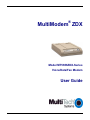
1
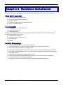
®
MultiModem ZDX
Model MT5656ZDX-Series
Voice/Data/Fax Modem
User Guide
Copyright and Technical Support
User Guide
MT5656ZDX-Series
PN S000248K Revision K
This publication may not be reproduced, in whole or in part, without prior expressed written permission from Multi-Tech Systems,
Inc. All rights reserved. Copyright © 2003-11 by Multi-Tech Systems, Inc.
Multi-Tech Systems, Inc. makes no representations or warranties with respect to the contents hereof and specifically
disclaims any implied warranties of merchantability or fitness for any particular purpose. Furthermore, Multi-Tech Systems,
Inc. reserves the right to revise this publication and to make changes in the content hereof without obligation of Multi-Tech
Systems, Inc. to notify any person or organization of such revisions or changes.
Revision
Date
Description
H
I
06/18/07
08/12/08
J
05/04/09
10/06/09
K
06/03/11
Revise tech support information
Update Package Contents and Safety Warnings. Added the WEEE statement. Added
the RS-232 cable to the Ship Kit Contents.
Added a link to the Multi-Tech Web site for the Warranty Statement.
Added the RoHS statement. Added the 47 CFR FCC Part 15 Class B statement.
Added TAPI compliant. Added Web portal information.
Remove all references to CDs.
Trademarks
MultiModem, Multi-Tech, and the Multi-Tech logo are trademarks of Multi-Tech Systems, Inc.
Adobe and Acrobat are trademarks of Adobe Systems, Incorporated. Microsoft, Windows and Windows 2000+ are either
registered trademarks or trademarks of Microsoft Corporation in the United States and/or other countries. All other brand
and product names mentioned in this publication are trademarks or registered trademarks of their respective companies.
Contacting Multi-Tech Support
In order to better serve our customers, manage support requests and shorten resolution times, we have created the online web
portal allowing you to submit questions regarding Multi-Tech products directly to our technical support team. Get answers to
your most complex questions, ranging from implementation, troubleshooting, product configuration, firmware upgrades and
much more.
To create an account and submit a Support Case on the Portal, visit https://support.multitech.com
Online Web Portal
The Knowledge Base provides immediate answers to your questions and gives you access to support resolutions for all MultiTech products. Visit our support area on the website for other support services.
Knowledge Base and Support Services: www.multitech.com/en_US/SUPPORT
Technical Support
Business Hours: M-F, 9am to 5pm CST
Country
By Email
Europe, Middle East, Africa: [email protected]
U.S., Canada, all others:
[email protected]
By Phone
+(44) 118 959 7774
(800) 972-2439 or (763) 717-5863
Warranty
To read the warranty statement for your product, please visit:
http://www.multitech.com/en_US/COMPANY/Policies/warranty/
Patents
This device is covered by one or more of the following patents: 6,031,867; 6,012,113; 6,009,082; 5,905,794; 5,864,560;
5,815,567; 5,815,503; 5,812,534; 5,809,068; 5,790,532; 5,764,628; 5,764,627; 5,754,589; D394,250; 5,724,356; 5,673,268;
5,673,257; 5,644,594; 5,628,030; 5,619,508; 5,617,423; 5,600,649; 5,592,586; 5,577,041; 5,574,725; D374,222; 5,559,793;
5,546,448; 5,546,395; 5,535,204; 5,500,859; 5,471,470; 5,463,616; 5,453,986; 5,452,289; 5,450,425; D361,764; D355,658;
D355,653; D353,598; D353,144; 5,355,365; 5,309,562; 5,301,274. Other patents pending.
World Headquarters
Multi-Tech Systems, Inc.
2205 Woodale Drive
Mounds View, MN 55112 U.S.A
(763) 785-3500 or (800) 328-9717
Fax (763) 785-9874
Technical Support (800) 972-2439
2
Multi-Tech Systems, Inc. MT5656ZDX User Guide
Table of Contents
Contents
Chapter 1 - Introduction ................................................................................................................................................. 4
Product Description ................................................................................................................................................ 4
Chapter 2 - Hardware Installation ................................................................................................................................... 5
Ship Kit Contents .................................................................................................................................................... 5
You Supply ............................................................................................................................................................. 5
Safety Warnings ..................................................................................................................................................... 5
Technical Specifications ............................................................................................................................................. 6
Overview – Connecting the Modem to Your System ............................................................................................. 8
Voice Connections (Voice option only)................................................................................................................. 10
Installing the Modem Driver .................................................................................................................................. 11
Connecting to the Internet .................................................................................................................................... 12
Dial-Up Networking............................................................................................................................................... 12
Chapter 3 - Operation ............................................................................................................................................... 13
About the LED Indicators ..................................................................................................................................... 13
Configuring Your Software ................................................................................................................................... 14
Configuring Your Modem ..................................................................................................................................... 14
Chapter 4 - AT Commands ....................................................................................................................................... 15
See Commands Reference Guides...................................................................................................................... 15
Chapter 5 - Troubleshooting .................................................................................................................................... 16
None of the Indicators Light Up ............................................................................................................................ 16
The Modem Does Not Respond to Commands ................................................................................................... 17
The Modem Dials But Cannot Connect ................................................................................................................ 18
The Modem Disconnects While Online ................................................................................................................ 19
The Modem Cannot Connect When Answering ................................................................................................... 19
There Are Garbage Characters on the Monitor.................................................................................................... 19
The Modem Doesn’t Work with Caller ID ............................................................................................................. 19
Appendix A – Regulatory Compliance.................................................................................................................... 20
Appendix B – Installing a Modem in Linux............................................................................................................. 22
Appendix C – Upgrading the Modem ...................................................................................................................... 23
Upgrade Overview ................................................................................................................................................ 23
Step 1: Identify the Modem Firmware ....................................................................................................... 23
Step 2: Identify the Current Firmware Version.......................................................................................... 23
Step 3: Download the Upgrade File .......................................................................................................... 24
Step 4: Extract the Upgrade Files ............................................................................................................. 24
Step 5: Upgrade the Modem’s Firmware .................................................................................................. 24
Step 6: Restore Your Parameters ............................................................................................................. 24
Appendix D – Waste Electrical and Electronic Equipment Directive (WEEE) .................................................... 25
Appendix E – RoHS .................................................................................................................................................. 26
Restriction of the Use of Hazardous Substances (RoHS).................................................................................... 26
Index ............................................................................................................................................................................ 28
Multi-Tech Systems, Inc. MT5656ZDX User Guide
3
Chapter 1 - Introduction
Congratulations on your purchase of the Multi-Tech MT5656ZDX-Series modem.
●
The Multi-Tech MT5656ZDX modem is your data/fax modem.
●
The MT5656ZDX-V offers your voice option.
You have acquired one of the finest intelligent data/fax or voice/data/fax modems available today from one of the
world’s oldest modem manufacturers: Multi-Tech Systems, Inc. This user guide will help you install, configure,
test, and use your modem.
Product Description
The Multi-Tech MT5656ZDX and MT5656ZDX-V modems are compatible with the ITU-TV.92 protocol that
provide quick connections, downstream transmissions at speeds up to 56K bps, and upstream transmissions at
speeds up to 48K bps when connected to V.92-compatible Internet Service Providers. The V.92 protocol is
able to send downstream from the Internet to your computer at these speeds because data on the telephone
network typically is converted from digital to analog only once before it reaches your modem. Upstream
transmissions and transmissions between client modems are limited to 33.6K bps, as are upstream
transmissions that are converted more than once on the telephone lines.
Modem features include Plug and Play operation. In standard mode, the modem can store up to four command
lines or telephone numbers of up to 40 characters each in nonvolatile memory. Other modem capabilities include
modem-on-hold, AT&T calling card tone detection, pulse and tone dialing, adaptive answer, V.42bis and V.44
data compression, and self-resetting lightning protection.
Please note that some V.92 features are turned off in the factory default configuration, and may need to be
turned on, depending on your needs.
4
Multi-Tech Systems, Inc. MT5656ZDX User Guide
Chapter 2 - Hardware Installation
This chapter shows you step-by-step how to set up your Multi-Tech modem, test it, and make your first calls.
Ship Kit Contents
●
●
●
●
●
One MultiModem ZDX (MT5656ZDX)
One set of four self-adhesive rubber feet
One power supply
One RS-232 cable (a DB9F to DB25M serial cable)
One RJ-11 telephone cable
You Supply
●
●
●
A computer with an available serial port
A nearby AC power outlet
A nearby phone jack
Optional: If you want speakerphone functions along with the ability to record sound or .WAV files through the
sound card at the same time, you need:
● One stereo PC microphone
● One stereo male to male patch cord
● One sound card
● Speakers
Safety Warnings
●
●
●
●
●
●
●
●
●
Use this product only with UL- and CUL-listed computers.
To reduce the risk of fire, use only UL-listed 26 AWG (.41mm) or larger telephone wiring.
Never install telephone wiring during a lightning storm.
Never install a telephone jack in a wet location unless the jack is specifically designed for wet locations.
Never touch uninsulated telephone wires or terminals unless the telephone line has been disconnected at
the network interface.
Use caution when installing or modifying telephone lines.
Avoid using a telephone during an electrical storm; there is a risk of electrical shock from lightning.
Do not use a telephone in the vicinity of a gas leak.
The telephone cord is to be disconnected before accessing the inside of the equipment.
Multi-Tech Systems, Inc. MT5656ZDX User Guide
5
Chapter 2 - Hardware Installation
Technical Specifications
The MultiModemZDX modem meets the following specifications:
6
Trade Name
MultiModemZDXTM
Model Number
MT5656ZDX
Server-to-Client Data Rates
V.90 speeds when accessing a V.90 or V.92 server (actual speed
depends on server capabilities and line conditions) *Though these
modems are capable of 56K bps download performance, line
impairments, public telephone infrastructure and other external
technological factors currently prevent maximum 56K bps
connections.
Client-to-Server Data Rates
Up to 50Kbps when accessing a V.92 server (actual speed depends
on server capabilities and line conditions); otherwise, the same as
client-to-client data lines.
Client-to-Client Data Rates
33600,31200, 28800, 26400, 24000, 21600, 19200, 16800, 14400,
12000, 9600, 7200, 4800, 2400, 1200, 0-300 bps
Fax Data Rates
14400, 12000, 9600, 7200, 4800, 2400, 1200, 0-300 bps
Data Format
Serial, binary, asynchronous
Modem Compatibility
ITU-T V.92, V.90, V.34 enhanced, V.34, V.34bis, V.32, V.22bis, V.22;
Bell 212A and 103; ITU-T V.21; V.42, V.42bis, V.44
Fax Compatibility
T.4, T30, V.21, V.27ter, V.29, V.34, V.17; TIA/EIA 578 Class 1 and
Class 2, TR29.2
Video Compatibility
ITU-T V.80 for H.34 video conferencing
Voice Compatibility
AT+V/TAM command set
Voice Mode Sampling
Up to 44.100 KHz (down-sampled to 11.025 KHz)
Error Correction
ITU-T V.42 (LAP-M or MNP 4)
Data Compression
ITU-T V.44 (4:1 throughput), V.42bis (4:1 throughput), MNP 5
(2:1 throughput)
Speed Detection
Automatic speed detection and switching between available speeds
Speed Conversion
Serial port data rates adjustable to 300; 1200; 2400; 4800; 9600;
19,200; 38,400; 57,600; 115,200 bps
Mode of Operation
Fax online modes, full duplex data over dial-up; voice
Flow Control
XON/XOFF (software), RTS/CTS (hardware)
Intelligent Features
Plug and play, full AT command compatible, autodial, redial, repeat
dial, pulse or tone dial, dial pauses, auto answer, adaptive
answer; EIA extended auto mode; caller ID, adaptive line probing;
automatic symbol and carrier frequency during start-up, retrain and
rate renegotiation, DTMF detection, call status display, auto-parity
and data rate selections, keyboard-controlled modem options, nonvolatile memory, US Caller ID reporting; quick-connect startup, TAPI
compliant.
Command Buffer
40 Characters
Transmission Level
-11 dBm (North America and Pan Euro) - varies by country setting
Frequency Stability
±0.01%
Receiver Sensitivity
-43 dBm under worst-case conditions
AGC Dynamic Range
43 dB
Multi-Tech Systems, Inc. MT5656ZDX User Guide
Chapter 2 - Hardware Installation
Connectors
Two RJ-11 phone jacks, DB25F RS-232C connector, power
connector
Cables
One modular telephone cable
Diagnostics
Local analog loop, local digital loop, remote digital loop
Speaker
Speaker for call progress monitoring
Speaker and Microphone Jacks MultiModemZDXV
Manual Controls
Power switch
Environmental
Temperature range 0°–50°C (32°–120°F); humidity range 20–90%
(non-condensing)
Storage Temperature
-10° to +85°C (14°- 185° F)
Power Consumption
150 mA @ 9 VDC
Dimensions
10.8 cm wide x 14.8 cm long x 2.9 high (4.25” × 5.8” x 1.15”)
Weight
224 g (8 oz)
Operating Systems
Tested for use with Windows 2000+ and Linux (2.2.x kernel)
Warranty
2 years
Multi-Tech Systems, Inc. MT5656ZDX User Guide
7
Chapter 2 - Hardware Installation
Overview – Connecting the Modem to Your System
Turn off your computer. Place the modem in a convenient location, then connect it to your computer’s serial port, to the phone
line, to AC power, and to your phone (phone is optional).
MT5656ZDX Connections.
MT5656ZDX Connections
Connect the Modem to Your PC (RS-232 Connection)
Plug one end of the RS-232 serial cable into the RS-232 connector on the modem, and plug the other
end into a serial port connector on your computer.
Connect the Modem to the Telephone Line (Line Connection)
Plug one end of the phone cable into the modem’s LINE jack and the other end into a phone wall
jack. The phone cable is included with your modem.
Note: The LINE jack is not interchangeable with the PHONE jack. Do not plug the phone into the
LINE jack or the line cable into the PHONE jack.
(Optional) Connect the Modem to the Phone
For voice-only calls, plug a phone into the modem’s PHONE jack.
8
Multi-Tech Systems, Inc. MT5656ZDX User Guide
Chapter 2 - Hardware Installation
Connect the Power
Make sure the power switch is set to OFF. The power switch is located on the side panel of the modem.
Plug the power supply into a power outlet or power strip. Plug the other end into the PWR jack on the
modem.
CAUTION: Use only the power supply cable supplied with the modem. Use of any other power supply voids
the warranty and can damage the modem.
A Note About Power Connection, Surge Protectors, and Lightning
Power surges and other transient voltages on power lines, such as those caused by lightning
strikes, can damage or destroy your modem. Therefore, we recommend that you plug the modem into
a surge protector rather than directly into a wall outlet, preferably a surge protector that provides
protection against electrical spikes on the phone line as well as on the power line. Note that not even
a surge protector can guard against damage from a nearby lightning strike. During an electrical
storm, it is safest to unplug your computer equipment from both the power outlet and the phone line.
Power-On Test
Test the modem by turning it on (an on-off switch is located on the side panel). When you apply
power, the modem performs a diagnostic self-test. The PWR indicator lights; and if a terminal program is
running, the TR indicator also lights. If this does not happen, check that the power switch is on, the
power supply is solidly connected, and the AC outlet is live. If these measures do not work see the
Troubleshooting chapter.
Note: The Federal Communications Commission (FCC) and Industry Canada impose certain
restrictions on equipment connected to public phone systems. For more information, see Appendix
A.
Multi-Tech Systems, Inc. MT5656ZDX User Guide
9
Chapter 2 - Hardware Installation
Voice Connections (Voice option only)
Voice Connections for Voice Models
(Optional) Connect the Modem to the Phone
For voice-only calls, plug a phone into the modem’s PHONE jack.
Connect the Microphone
For voice mail or speakerphone applications, plug an unamplified microphone into the MIC jack on
the side of the modem. The microphone should have a stereo 1/8-inch (3.5mm) mini plug. Do not use
a monophonic microphone.
Connect the Speaker
For speakerphone or voice mail applications, use a 1/8-inch (3.5mm) plug male-to-male stereo
patch cord to connect the SPKR jack on the side of the modem to the LINE IN jack on your sound
card. If your sound card does not have a LINE IN jack, use its MIC jack. The stereo male-to-male
patch cord can be purchased at a local PC retail store.
If you do not have a sound card, you can plug an amplified speaker directly into the SPKR jack.
10
Multi-Tech Systems, Inc. MT5656ZDX User Guide
Chapter 2 - Hardware Installation
Installing the Modem Driver
If you use Windows 2000 or newer, you must install the modem driver. If you use another operating system, see
Appendix B.
When operating the modem under Windows, the modem driver can be installed by using the Plug and Play
feature. Follow the procedure below.
1. Make sure your modem is connected properly, and then turn on your computer. Windows should
detect your new modem and open the Welcome to the Found New Hardware wizard.
Note: If Windows cannot find a modem, your modem may be turned off, or it may be plugged into the
wrong connector on your computer. See “Troubleshooting” in the User Guide.
2. From the Browse function in the Install Wizard, point to the Temporary folder you created on your local PC
to store the driver that you downloaded from the Multi-Tech website.
3. Windows installs and configures the modem.
4. Click Finish to exit.
Multi-Tech Systems, Inc. MT5656ZDX User Guide
11
Chapter 2 - Hardware Installation
Connecting to the Internet
Your Multi-Tech modem is your gateway to the Internet and the World Wide Web. To access the Internet and Web
via your modem, you must establish a dial-up account with an Internet service provider (ISP). To locate an ISP
near you, look in a local directory or computer publication. Your ISP should provide you with the following
information:
●
User name (also called user ID)
●
Password
●
Access number (the number you call to connect to the server)
●
Host name and/or domain name
●
Domain Name Server (DNS) server address
If, besides the Web, you use the Internet for email and newsgroups, your ISP should also provide you with the
following information:
●
Email or POP mail address
●
POP server address
●
Mail or SMTP address
●
News or NNT server address
Dial-Up Networking
Before you can connect to the Internet, you must set up a remote-node client program on your computer. The
Windows version is called Dial-Up Networking. Dial-Up Networking establishes your connection to the ISP’s server,
which is the shared computer that manages calls from clients (your computer) to the Internet. Most, if not all,
Windows browsers start Dial-up Networking automatically when you open them.
For instructions on how to set up Dial-Up Networking, consult your ISP or your operating system’s online help or
printed documentation. Many ISPs include with their service a program that will instruct and configure Dial-Up
Networking automatically for you.
12
Multi-Tech Systems, Inc. MT5656ZDX User Guide
Chapter 3 - Operation
Like any modem, your Multi-Tech modem operates only under the control of a communications program, such as
the communications program included with your modem. It also operates under other general-purpose data
communication programs, such as Windows Terminal and HyperTerminal. For information on how to use the
modem with the communications program of your choice, please refer to the documentation provided with the data
communications program.
An experienced modem user can configure the program’s software to change the way the software interacts with a
modem and configure the modem to change the way it operates.
Front Panel
About the LED Indicators
The modem has ten LED indicators on the front panel that indicate status and activity:
TD
Transmit Data
Flashes when the modem is transmitting data to another modem.
RD
Receive Data
Flashes when the modem is receiving data from another modem.
CD
Carrier Detect
Lights when the modem detects a valid carrier signal from another modem. It is on when the modem
is communicating with the other modem, and off when the link is broken.
OH
Off-Hook
Lights when the modem is off-hook, which occurs when the modem is dialing, online, or answering
a call. The LED flashes when the modem pulse-dials.
TR
Terminal Ready
Lights when a communication program is using the modem. It means the modem is ready for an
outgoing or incoming call. It goes off when the communication program disconnects the serial port.
When it goes off, a connected modem will disconnect.
Note: When you turn on the modem, the PWR indicator lights; and if a terminal program is
running, the TR indicator also lights.
Multi-Tech Systems, Inc. MT5656ZDX User Guide
13
Chapter 3 - Operation
Configuring Your Software
You may use either the communication program included with your modem or a third-party program.
Communication programs designed for Windows normally do not need to be manually configured, since they
obtain configuration information from Windows. Though each communication program is different, the following
procedure should work with most of them.
1. Turn on your computer and run your communications program.
2. Find the dialog box or menu that lets you select your modem. (In Windows Terminal select Settings |
Modem Commands; in HyperTerminal select File | Properties | Phone Number; and in the
communications program select Configure | General Configuration | Communication | Change
Modem.
3. Choose your modem from the program’s modem list. If it isn’t listed, choose a generic modem and modify
the settings as necessary.
4. Change the modem initialization string, if necessary. The factory default configuration works well for most
purposes. To load the factory default configuration, use AT&F. To load a custom configuration that was
saved using the &W command, use ATZ. Note that the Z command must be in a command string by
itself. For a Macintosh, the initialization string should include the &D0 command. If you do not want the
modem to always answer the phone, add S0=0 to the string. To use Caller ID with the modem, add
S0=2 to the string (Caller ID information is sent between the first and second rings, so the phone must
ring at least twice before the modem picks up the line). Depending on the software, you might have to
end the string with a carriage return character (^M).
Note: To change the modem’s default configuration, type new commands in the communication program’s terminal window, adding the &W command to store them in the modem’s nonvolatile memory. For
instance, to create a default configuration for a Macintosh computer that turns off auto answer, type
AT&F&D0S0=0&W. The new configuration loads automatically whenever the modem is turned on or
receives the ATZ command.
5. Select the port the modem is connected to (normally COM1 or COM2).
6. Select your serial port speed. This can be labeled “maximum speed,” “DTE bps,” or “baud rate.” Ideally, if
you use data compression, you should set your serial port baud rate to four times the modem’s maximum
transmission speed or faster; however, few files can be compressed enough to require speeds that high,
and not all serial ports can handle speeds that high.
7. If the communication program has an autobaud selection, make sure it is disabled. Autobaud applies only to
older modems, and can cause problems if enabled.
8. If the program allows you to edit the no-connect messages (NO CARRIER, BUSY, NO ANSWER, NO
DIAL TONE), make sure there is no space between DIAL and TONE in NO DIAL TONE.
9. Refer to the program manual or online help for other configuration choices. In most cases you can
accept the default values.
Configuring Your Modem
Your modem normally is configured through Windows or through the communication program you are using.
The default settings work best for most purposes. However, you also can configure your modem by sending
AT commands to the modem. See the AT Command Reference Guide for a list of AT (data) commands and
how to use them.
14
Multi-Tech Systems, Inc. MT5656ZDX User Guide
Chapter 4 - AT Commands
See Commands Reference Guides
AT Commands and Voice Commands are in the AT Command Reference Guide.
Fax Class 1 Commands and Fax Class 2 Commands are documented in separate Fax Reference Guides. All
Reference Guides are included on the Multi-Tech Web site.
Multi-Tech Systems, Inc. MT5656ZDX User Guide
15
Chapter 5 - Troubleshooting
Your modem was thoroughly tested at the factory before it was shipped. If you are unable to make a successful
connection, or if you experience data loss or garbled characters during your connection, check the list of
troubleshooting procedures before calling Multi-Tech.
●
●
●
●
●
●
●
●
●
●
None of the LEDs light when the modem is on.
The modem does not respond to commands.
The modem dials but is unable to make a connection.
The modem disconnects while online.
The modem cannot connect when answering.
File transfer is slower than it should be.
Data is being lost.
There are garbage characters on the monitor.
The modem doesn’t work with Caller ID.
Fax and data software can’t run at the same time.
If you experience problems, please check the following possibilities before calling Technical Support.
None of the Indicators Light Up
When you turn on the modem, the PWR indicator and the terminal turn on. If the LEDs remain off, the modem is
probably not receiving power.
●
●
●
●
●
●
●
Make sure the modem’s power switch is on, especially if you normally turn the modem on by turning on a
power strip.
If the modem is plugged into a power strip, make sure the power strip is plugged in and its power switch is
on.
Make sure the transformer module is firmly connected to the modem and to the wall outlet or power strip.
If the power strip is on and the modem switch is on, try moving the transformer module to another outlet on
the power strip.
Test that the outlet is live by plugging another device, such as a lamp, into it.
The modem or the DC power transformer may be defective. If you have another Multi-Tech modem, try
swapping modems. If the problem goes away, the first modem or the DC power transformer may be defective.
Call Technical Support for assistance.
CAUTION: Do not under any circumstances replace the transformer module with one designed for another product.
Doing so can damage the modem and void your warranty.
16
Multi-Tech Systems, Inc. MT5656ZDX User Guide
Chapter 5 - Troubleshooting
The Modem Does Not Respond to Commands
●
Make sure the modem is plugged in and turned on. (See “None of the Indicators Light.”)
●
Make sure you are issuing the modem commands from the data communications program, either manually
in terminal mode or automatically by configuring the software. (You cannot send commands to the
modem from the DOS prompt.)
●
Make sure you are in terminal mode in your data communications program, then type AT and press
ENTER. If you get an OK response from your modem, your connections are good and the problem likely is
in the connection setup in your communications program.
●
If you don’t get an OK, the problem may still be in the communications program. Make sure you have done
whatever is necessary in your software to make a port connection. Not all communication programs
connect to the COM port automatically. Some connect when the software loads and remain connected until
the program terminates. Others can disconnect without exiting the program. The modem’s TR indicator
lights to show that the software has taken control of the modem through the COM port.
●
Your communications program settings may not match the physical port the modem is connected to. The
serial cable might be plugged into the wrong connector—check your computer documentation to make
sure. Or you might have selected a COM port in your software other than the one the modem is physically
connected to—compare the settings in your software to the physical connection.
●
If the modem is on, the cable is plugged into the correct port, the communications program is
configured correctly, and you still don’t get an OK, the fault might be in the serial cable. Make sure it is
firmly connected at both ends.
●
Is this the first time you have used the cable? If so, it may not be wired correctly. Check the cable description on the packaging to make sure the cable is the right one for your computer.
●
Peripheral expansion cards, such as sound and game cards, might include a serial port preconfigured as
COM1 or COM2. The extra serial port, or the card itself, may use the same COM port, memory address, or
interrupt request (IRQ) as your communication port. Be sure to disable any unused ports.
Windows 9x and 2000: Right-click on My Computer, select Properties from the menu, click on the
Device Manager tab, double-click on Ports, then double-click on the communication port your modem is
connected to. In the port’s Properties sheet, click on the Resources tab to see the port’s input/output
range and interrupt request. If another device is using the same address range or IRQ, it appears in the
Conflicting Device List. Uncheck Use automatic settings to change the port’s settings so they do not
conflict with the other device, or select the port the conflicting device is on and change it instead. If you
need to open your computer to change switches or jumpers on the conflicting device; refer to the device’s
documentation.
●
The serial port might be defective. If you have another serial port, install the modem on it, change the
COM port setting in your software, and try again.
●
The modem may be defective. If you have another Multi-Tech modem, try swapping modems. If the
problem goes away, the first modem may be defective. Call Technical Support for assistance.
Multi-Tech Systems, Inc. MT5656ZDX User Guide
17
Chapter 5 - Troubleshooting
The Modem Dials But Cannot Connect
There can be several reasons the modem fails to make a connection. Possibilities include:
●
Lack of a physical connection to the telephone line.
●
A missing dial tone.
●
A busy signal.
●
A wrong number.
●
No modem at the other end.
●
A faulty modem, computer, or software at the other end.
●
Incompatibility between modems.
You can narrow the list of possibilities by using extended result codes. Extended result codes are enabled by
default. If they have been disabled, include V1X4 in the modem’s initialization string, or in terminal mode enter
ATV1X4 and press ENTER. When you dial again, the modem reports the call’s progress.
●
If the modem reports NO DIAL TONE, check that the modem’s phone line cable is connected to both the
modem’s LINE jack (not the PHONE jack) and the phone wall jack. If the cable looks secure, try
replacing it. If that doesn’t work, the problem might be in your building’s phone installation. To test the
building installation, plug a phone into your modem’s phone wall jack and listen for a dial tone. If you
hear a dial tone, your modem might be installed behind a corporate phone system (PBX) with an internal
dial tone that sounds different from the normal dial tone. In that case, the modem might not recognize the
dial tone and might treat it as an error. Check your PBX manual to see if you can change the internal
dial tone; if you can’t, change your modem’s initialization string to replace X4 with X3, which will cause
the modem to ignore dial tones (note, however, that X3 is not allowed in some countries, such as France
and Spain).
●
If the modem reports BUSY, the other number might be busy, in which case you should try again later, or it
might indicate that you have failed to add a 9, prefix to the phone number if you must dial 9 for an outside
line.
If you must dial 9 to get an outside line, the easiest way to dial it automatically is to include it in the
modem’s dial prefix, e.g., ATDT9. Note the comma, which inserts a pause before the number is dialed. By
inserting 9, into the dial prefix, you do not have to include it in each directory entry.
18
●
If the modem reports NO ANSWER, the other system has failed to go off-hook, or you might have dialed a
wrong number. Check the number.
●
If the modem reports NO CARRIER, the phone was answered at the other end, but no connection was
made. You might have dialed a wrong number, and a person answered instead of a computer, or you might
have dialed the correct number but the other computer or software was turned off or faulty. Check the
number and try again, or try calling another system to make sure your modem is working. Also, try calling
the number on your telephone. If you hear harsh sounds, then another modem is answering the call,
and the modems might be having problems negotiating because of modem incompatibilities or line noise.
Try connecting at a lower speed.
Multi-Tech Systems, Inc. MT5656ZDX User Guide
Chapter 5 - Troubleshooting
The Modem Disconnects While Online
●
If you have Call Waiting on the same phone line as your modem, it can interrupt your connection when
someone tries to call you. If you have Call Waiting, disable it before each call. In most phone areas in North
America, you can disable Call Waiting by preceding the phone number with *70 (check with your local
phone company).
●
You can automatically disable Call Waiting by including the disabling code in the modem’s dial prefix (e.g.,
ATDT*70,—note the comma, which inserts a pause before the number is dialed). To change the dial
prefix in Windows Terminal, select Settings | Modem Commands. To change it in HyperTerminal,
select Connect from the Call menu, click Dialing Properties, check This location has Call Waiting, and
select the correct code for your phone service.
●
If you have extension phones on the same line as your modem, you or someone else can interrupt the
connection by picking up another phone. If this is a frequent problem, disconnect the extension phones
before using the modem, or install another phone line especially for the modem.
●
Check for loose connections between the modem and the computer, the phone jack, and AC power.
●
You might have had a poor connection because of line conditions or the problem might have originated on
the other end of the line. Try again.
●
If you were online, it might have hung up on you because of lack of activity on your part or because you
exceeded your time limit for the day. Try again.
The Modem Cannot Connect When Answering
Autoanswer might be disabled. Turn on autoanswer in your data communications program or send the
command ATS0=1 (ATS0=2 if you have Caller ID service) to your modem in terminal mode.
There Are Garbage Characters on the Monitor
●
Your computer and the remote computer might be set to different word lengths, stop bits, or parities. If you
have connected at 8-N-1, try changing to 7-E-1, or vice-versa, using your communications program.
●
You might be experiencing line noise. Enable error correction, if it is disabled, or hang up and call
again; you might get a better connection the second time.
●
Try entering the &V1 command to display information about the last connection, making a screen print
of the connection statistics, and checking for parameters that might be unacceptable.
The Modem Doesn’t Work with Caller ID
●
Caller ID information is transmitted between the first and second rings, if the modem is set to answer after
only one ring (S0=1), the modem will not receive Caller ID information. Check your initialization string, and
if necessary change it to set the modem to answer after the second ring (S0=2).
●
Make sure that you have Caller ID service from your telephone company.
Multi-Tech Systems, Inc. MT5656ZDX User Guide
19
Appendix A – Regulatory
Compliance
47 CFR – FCC Part 15 Class B
This equipment has been tested and found to comply with the limits for a Class B digital device, pursuant to
47 CFR – FCC Part 15 regulations. The stated limits in this regulation are designed to provide reasonable protection against harmful
interference in a residential environment. This equipment generates, uses, and can radiate radio frequency energy, and if not installed and used
in accordance with the instructions, may cause harmful interference to radio communications. However, there is no guarantee that interference
will not occur in a particular installation. If this equipment does cause harmful interference to radio or television reception, which can be
determined by turning the equipment off and on, the user is encouraged to try to correct the interference by one or more of the following
measures:
●
Reorient or relocate the receiving antenna.
●
Increase the separation between the equipment and receiver.
●
Plug the equipment into an outlet on a circuit different from that to which the receiver is connected.
●
Consult the dealer or an experienced radio/TV technician for help.
This device complies with 47 CFR – FCC Part 15 rules. Operation of this device is subject to the following conditions:
(1)
This device may not cause harmful interference, and
(2)
This device must accept any interference that may cause undesired operation.
Warning: Changes or modifications to this unit not expressly approved by the party responsible for compliance could void the user’s authority to
operate the equipment.
This Class B digital apparatus meets all requirements of the Canadian Interference-Causing Equipment Regulations. Cet
appareil numérique de la classe B respecte toutes les exigences du Reglement Canadien sur le matériel brouilleur.
FCC Part 68 Telecom
1.
2.
3.
4.
5.
6.
7.
8.
9.
20
This equipment complies with part 68 of the Federal Communications Commission Rules. On the outside surface of this equipment is a
label that contains, among other information, the FCC registration number. This information must be provided to the telephone company.
The suitable USOC jack (Universal Service Order Code connecting arrangement) for this equipment is shown below. If applicable, the
facility interface codes (FIC) and service order codes (SOC) are shown.
An FCC-compliant telephone cord and modular plug is provided with this equipment. This equipment is designed to be connected to
the telephone network or premises wiring using a compatible modular jack that is Part 68 compliant. See installation instructions for
details.
The ringer equivalence number (REN) is used to determine the number of devices that may be connected to the telephone line.
Excessive RENs on the telephone line may result in the device not ringing in response to an incoming call. In most, but not all, areas
the sum of the RENs should not exceed 5.0. To be certain of the number of devices that may be connected to the line, as determined
by the total RENs, contact the local telephone company.
If this equipment causes harm to the telephone network, the telephone company will notify you in advance that temporary
discontinuance of service may be required. But if advance notice is not practical, the telephone company will notify you as soon as
possible. Also, you will be advised of your right to file a complaint with the FCC if you believe it is necessary.
The telephone company may make changes in its facilities, equipment, operations, or procedures that could affect the operation of the
equipment. If this happens, the telephone company will provide advance notice in order for you to make necessary modifications in
order to maintain uninterrupted service.
If trouble is experienced with this equipment (the model of which is indicated below) please contact Multi-Tech Systems, Inc. at the
address shown below for details of how to have repairs made. If the trouble is causing harm to the telephone network, the telephone
company may request you remove the equipment from the network until the problem is resolved.
No repairs are to be made by you. Repairs are to be made only by Multi-Tech Systems or its licensees. Unauthorized repairs void
registration and warranty.
This equipment should not be used on party lines or coin lines.
Multi-Tech Systems, Inc. MT5656ZDX User Guide
Appendix A – Regulatory Compliance
10. If so required, this equipment is hearing-aid compatible.
Manufacturer:
Multi-Tech Systems, Inc.
Trade Name:
MultiModem
Model Number:
MT5656ZDX
Registration No:
US:AN7M501B56ZDX
Ringer Equivalence No:
0.3B
Modular Jack (USOC):
RJ1 1C or RJ1 1W (single line)
Service Center in USA:
Multi-Tech Systems, Inc.
2205 Woodale Drive
Mounds View, MN 55112
Canadian Limitations Notice
Notice: The ringer equivalence number (REN) assigned to each terminal device provides an indication of the maximum number of
terminals allowed to be connected to a telephone interface. The termination on an interface may consist of any combination of devices
subject only to the requirement that the sum of the ringer equivalence numbers of all the devices does not exceed 5.
Notice: The Industry Canada label identifies certificated equipment. This certification means that the equipment meets certain
telecommunications network protective, operational and safety requirements. The Industry Canada label does not guarantee the equipment will
operate to the user’s satisfaction.
Before installing this equipment, users should ensure that it is permissible to be connected to the facilities of the local telecommunications
company. The equipment must also be installed using an acceptable method of connection. The customer should be aware that compliance
with the above conditions may not prevent degradation of service in some situations. Repairs to certified equipment should be made by an
authorized Canadian maintenance facility designated by the supplier. Any repairs or alterations made by the user to this equipment or
equipment malfunctions may give the telecommunications company cause to request the user to disconnect the equipment.
Users should ensure for their own protection that the electrical ground connections of the power utility, telephone lines and internal metallic water
pipe system, if present, are connected together. This precaution may be particularly important in rural areas.
Caution: Users should not attempt to make such connections themselves, but should contact the appropriate
electric inspection authority, or electrician, as appropriate.
International Modem Restrictions
Some dialing and answering defaults and restrictions may vary for international modems. Changing settings may cause a modem to become
non-compliant with national telecom requirements in specific countries. Also note that some software packages may have features or lack
restrictions that may cause the modem to become non-compliant.
EMC, Safety, and R&TTE Directive Compliance
The CE mark is affixed to this product to confirm compliance with the following European Community Directives:
●
Council Directive 2004/108/EC of 15 December 2004 on the approximation of the laws of Member States relating to electromagnetic
compatibility;
and
●
Council Directive 2006/95/EC of 12 December 2006 on the harmonization of the laws of Member States relating to electrical
equipment designed for use within certain voltage limits;
and
●
Council Directive 1999/5/EC of 9 March 1999 on radio equipment and telecommunications terminal equipment and the mutual
recognition of their conformity.
Multi-Tech Systems, Inc. MT5656ZDX User Guide
21
Appendix B – Installing a Modem in
Linux
This appendix explains how to install a modem on a PC operating under the RedHat Linux 6.2 operating
system. Other versions of RedHat and other Linux operating systems should be similar. Briefly, in Linux, you do
not need drivers for most standard external modems and most internal ISA bus modems. Programs in Linux
commonly call upon the port, rather than the modem.
Standard Linux Serial Port Definitions
Port
Com 1
Com 2
Com 3
Com 4
Linux Port
ttyS0
ttyS1
ttyS2
ttyS3
Installation
Connect the external modem to an available serial port.
Setup
This section describes how to make sure Linux can talk to the modem and be able to dial up to the Internet.
Using the Terminal Program Minicom to Verify Operation
At the command prompt, type minicom –s and press ENTER.
Select Serial port setup and press ENTER.
From Serial port setup, use the A key to access Serial Device, and then press ENTER.
Press ESC.
You are now in the Minicom terminal. Type AT and press ENTER. The screen should display OK to verify the
operation. Alternately, dial a phone number to verify line operation
6. To leave Minicom, press CTRL + A, and then press Z. 7. On the help menu, press X to exit.
1.
2.
3.
4.
5.
Using the Modem to Call the Internet
Linux allows different graphic user interfaces (GUI). In the following steps, the Gnome Desktop GUI is used. It is
assumed that the Internet Service Provider (ISP) being called assigns the Domain Name Service (DNS) and
Internet Protocol (IP) addresses. For information on DNS or IP, see the Linux OS owner’s manual or contact ISP.
1.
2.
3.
4.
5.
6.
7.
8.
On the Task Bar at the bottom of the screen, select the Gnome Footprint.
Select Internet from the menu.
Select Dialup Configuration Tool.
Select Add, and then click Next.
Enter the connection name and phone number, and then click Next.
Enter your user name and password, and then click Next.
Select Normal ISP if your ISP is not listed, and then click Next.
Click Finish.
Calling the ISP
1.
2.
3.
4.
5.
On the Task Bar at the bottom of the screen, select the Gnome Footprint.
Select Internet from the menu.
Select RH PPP Dialer.
Select the connection name you entered in step 5 of the previous section. 5.
Click OK.
Linux can use different programs and desktops depending on who made the Linux operating system and what
version it is. The above procedures use the most commonly installed components of Red Hat 6.2. More details
can be found in the Linux OS owner’s manual.
To use the system to answer calls, Linux requires other programs to be installed, such as Mgetty and Mgetty+Sendfax,
depending on requirements. Each vendor of Linux usually has adequate information on installing these programs.
22
Multi-Tech Systems, Inc. MT5656ZDX User Guide
Appendix C – Upgrading the Modem
Your modem is controlled by semi-permanent software, called firmware, which is stored in flash memory.
Firmware is nonvolatile; that is, it remains stored in memory when the modem is turned off. However, it can be
changed by either the manufacturer or the user.
Since the firmware in your modem is stored in flash memory, you can upgrade it yourself in a few minutes by
using the following procedures.
Upgrade Overview
The upgrade procedure consists of the following steps, which are described in greater detail in the following
sections.
1. Identify the model number and firmware version of your modem.
2. Identify the current version of the firmware at the Multi-Tech Web site. If your modem already has the
current firmware, there is no need to update it.
3. Download the upgrade file for your modem.
4. Extract the firmware .HEX file and the appropriate flash upgrade program from the file you downloaded.
5. Document and clear your stored parameters.
6. Upgrade the modem’s firmware using the .HEX file and the flash upgrade program.
7. Restore your parameters.
Step 1: Identify the Modem Firmware
You must know the model number and firmware version of your Multi-Tech modem to know whether or not
you should update it.
1. Run your favorite terminal program. If you are using Windows 95, 98, 2000 or Windows NT, you can use
HyperTerminal. If you are using Windows 3.1, you can use Windows Terminal.
2. In the program’s terminal window, type AT&F. Even if you cannot see the AT&F command on your screen,
be sure to type it completely, and then press ENTER. If the modem does not respond with OK, repeat
the AT&F command.
3. Now type ATI3 and record your results. The firmware version should appear first in the response, which
should look similar to the following:
V2.300G-V90_2M_DLS
Step 2: Identify the Current Firmware Version
Identify the current version of the firmware at the Multi-Tech Web site. If your modem already has the current
firmware, there is no need to update it.
Using your favorite Web browser, go to http://www.multitech.com/en_US/SUPPORT/Updates/drivers/
Scroll down the table to your modem model number.
Look at the firmware version number for your modem.
If the firmware version number matches the firmware version number found in “Step 1: Identify the Modem
Firmware,” your modem has the current firmware version, and does not need to be updated.
5. If the firmware version number is greater than the firmware version number found in “Step 1: Identify the
Modem Firmware,” your modem has an older firmware version.
Continue with “Step 3: Download the Upgrade File.”
1.
2.
3.
4.
Warning: The first digit of the new firmware must match the first digit of the old firmware, or the modem may not
work properly; e.g., if your current firmware version is 4.16, replace it only with 4.xx firmware, not 6.xx firmware.
Multi-Tech Systems, Inc. MT5656ZDX User Guide
23
Appendix C – Upgrading the Modem
Step 3: Download the Upgrade File
1. If you are not already at the MultiModemZDX firmware page of the Multi-Tech Web site, follow the procedure in “Step 2: Identify the Current Firmware.”
2. Download the upgrade file for your modem by clicking its name, and save the file in a temporary folder on
your hard disk.
3. In the same section of the Web page, download the Flash Wizard utility for your operating system by
clicking it, and save it in the same folder.
Step 4: Extract the Upgrade Files
1. Install the Flash Wizard utility by double-clicking the file name in Windows Explorer.
2. Extract the upgrade files by double-clicking the file name. The extracted files include a .HEX file, which
contains the upgrade data, and a Readme file.
3. Copy the upgrade .S37 file into the Flash Wizard folder.
Step 5: Upgrade the Modem’s Firmware
Before you begin the following procedure, read the README.TXT file extracted from the upgrade archive file. Note
the file name for the boot code (e.g., 2MBPFL1 1 .S37) and the file name for the new firmware (e.g.,
BkQg300G.hex).
Warning: Never install an older version of firmware over a newer version. Doing so will destroy the Flash
PROM! If the Flash PROM is destroyed, the modem must be sent in for repair.
1. Run Flash Wizard by double-clicking its icon or file name, or by selecting it from the Start menu. The
Identifying Devices dialog box is displayed as Flash Wizard locates and identifies the devices connected
to your system.
Note: If the message ERROR: No valid devices detected is displayed, verify that the device is powered on
and that all cables are correctly and securely attached.
2. Click the modem to be upgraded, and then click Next to proceed.
3. Select the port to be upgraded from the Port list, select the appropriate .HEX file from the Hex File list, and
then click Next to continue.
Note: Do not use FLASHLDR.HEX. This file is used internally by Flash Wizard.
4. The Progress dialog box appears, showing a status bar that indicates the progress of the upgrade.
Caution: Any disruption of the program during this stage of the upgrade can cause your modem to become
inoperable. Wait for the Next button to become active before proceeding.
5. When the flash upgrade is complete, the message Programming Complete appears. Click Next to
continue.
6. The Results dialog box appears next. Click Finish to exit Flash Wizard.
Step 6: Restore Your Parameters
Your modem has been updated. You can now open your terminal program to reprogram your modem
parameters or to confirm the update by typing ATI3 in the terminal window and pressing Enter.
24
Multi-Tech Systems, Inc. MT5656ZDX User Guide
Appendix D – Waste Electrical and
Electronic Equipment Directive
(WEEE)
Waste Electrical and Electronic Equipment (WEEE) Directive
The WEEE directive places an obligation on manufacturers, distributors and retailers to take-back electronic
products at the end of their useful life. A sister Directive, ROHS (Restriction of Hazardous Substances),
complements the WEEE Directive by banning the presence of specific hazardous substances in the products
at the design phase. The WEEE Directive covers all Multi-Tech products being sold into the EU as of August
13, 2005. Manufacturers, distributors and retailers are obliged to finance the costs of recovery from municipal
collection points, reuse, and recycling of specified percentages per the WEEE requirements.
Instructions for Disposal of WEEE by Users in the European Union
The symbol shown below is on the product or on its packaging which indicates that this product must not be
disposed of with other waste. Instead, it is the user’s responsibility to dispose of the user’s waste equipment
by handing it over to a designated collection point for the recycling of electrical and electronic waste
equipment. The separate collection and recycling of waste equipment at the time of disposal will help to
conserve natural resources and ensure that it is recycled in a manner that protects human health and the
environment. For more information about where you can drop off your waste equipment for recycling, please
contact your local city office, your household waste disposal service or the seller from whom you purchased
the product.
Multi-Tech Systems, Inc. MT5656ZDX User Guide
25
Appendix E – RoHS
Restriction of the Use of Hazardous Substances (RoHS)
Multi-Tech Systems, Inc.
Certificate of Compliance
2002/95/EC
Multi-Tech Systems, Inc. confirms that this product now complies with the chemical concentration limitations set
forth in the directive 2002/95/EC of the European Parliament (Restriction Of the use of certain Hazardous
Substances in electrical and electronic equipment - RoHS)
These Multi-Tech Systems, Inc. products do not contain the following banned chemicals:
Lead, [Pb] < 1000 PPM
Mercury, [Hg] < 1000 PPM
Hexavalent Chromium, [Cr+6] < 1000 PPM
Cadmium, [Cd] < 100 PPM
Polybrominated Biphenyl, [PBB] < 1000 PPM
Polybrominated Diphenyl Ether, [PBDE] < 1000 PPM
Notes:
1.
Lead usage in some components is exempted by the following RoHS annex; therefore, higher lead
concentration could be found.
a. Lead in high melting temperature type solders (i.e., tin-lead solder alloys containing more than 85%
lead).
b. Lead in electronic ceramic parts (e.g., piezoelectronic devices).
26
Multi-Tech Systems, Inc. MT5656ZDX User Guide
Appendix E – RoHS
依照中国标准的有毒有害物质信息
根据中华人民共和国信息产业部 (MII) 制定的电子信息产品 (EIP)
标准-中华人民共和国《电子信息产品污染控制管理办法》(第 39 号),也称作中国
RoHS,下表列出了 Multi-Tech Systems Inc. 产品中可能含有的有毒物质 (TS) 或有害物质 (HS)
的名称及含量水平方面的信息。
有害/有毒物质/元素
(PB)
汞
(Hg)
印刷电路板
O
电阻器
铅
镉
多溴联苯
(CD)
六价铬
(CR6+)
(PBB)
多溴二苯醚
(PBDE)
O
O
O
O
O
X
O
O
O
O
O
电容器
X
O
O
O
O
O
铁氧体磁环
O
O
O
O
O
O
继电器/光学部
件
O
O
O
O
O
O
IC
O
O
O
O
O
O
二极管/晶体管
O
O
O
O
O
O
振荡器和晶振
X
O
O
O
O
O
调节器
O
O
O
O
O
O
电压传感器
O
O
O
O
O
O
变压器
O
O
O
O
O
O
扬声器
O
O
O
O
O
O
连接器
O
O
O
O
O
O
LED
O
O
O
O
O
O
螺丝、螺母以及
其它五金件
X
O
O
O
O
O
交流-直流电源
O
O
O
O
O
O
软件/文档 CD
O
O
O
O
O
O
手册和纸页
O
O
O
O
O
O
底盘
O
O
O
O
O
O
成分名称
X
表示所有使用类似材料的设备中有害/有毒物质的含量水平高于 SJ/Txxx-2006 限量要求。
O
表示不含该物质或者该物质的含量水平在上述限量要求之内。
Multi-Tech Systems, Inc. MT5656ZDX User Guide
27
Index
C
Connecting the Modem ...............................................................8
D
Data Rates ....................................................................................6
Dial-Up Networking ....................................................................12
E
EMC, Safety, and R&TTE Directive Compliance .........................21
F
Front Panel .................................................................................13
I
Internet service provider ..........................................................12
L
LED Indicators ............................................................................13
M
Modem Driver ...................................................................... 11, 13
R
RoHS ...........................................................................................27
S
Safety Warnings ...........................................................................5
Surge Protector ............................................................................9
T
Technical Specifications ...................................................................6
Troubleshooting .........................................................................16
V
Voice Connections ..................................................................10
W
Waste Electrical and Electronic Equipment (WEEE) Directive ....26
28
Multi-Tech Systems, Inc. MT5656ZDX User Guide