1
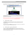
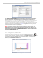
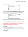
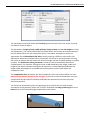
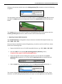
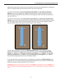
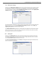
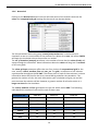
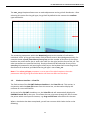
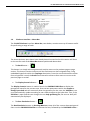
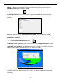
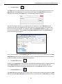
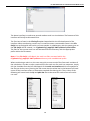
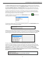
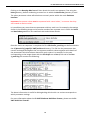
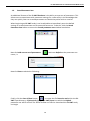
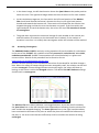
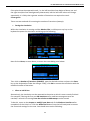
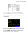
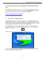
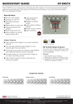
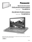
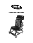
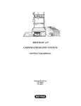
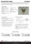
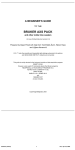
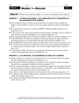
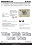
F1-VWT SimScene: F1 in Schools Virtual Wind tunnel F1-VWT SimScene – User Guide 1. Introduction The F1-VWT SimScene uses simple user-interfaces to enable the easy setting up and running of aerodynamic tests of air flow around an F1 in Schools type racing car. Clicking on the F1-VWT Desktop icon will launch the main F1-VWT SimScene interface seen below: The above interface is the starting point for any F1-VWT simulation and it contains several important features: The logo in the top left-hand corner of the window is a link to the F1-VWT documentation available on the CHAM Ltd. Website. Simply clicking this icon will launch a web browser to display this content. The banner image across the centre of the window is a link to the F1 in Schools UK website. Clicking this image launches a web browser to display this web page. A choice of competition class for the simulation. The user must select the competition class they wish to use by clicking (or scrolling to) either Formula One Class or Bloodhound SSC Class. The blue highlighting indicates the currently selected class. The logo in the bottom right-hand corner of the window and the Start Case button offer two ways to launch the SimScene. Clicking either of these buttons will start a new F1-VWT case for the competition class highlighted. 1 F1-VWT SimScene: F1 in Schools Virtual Wind tunnel After selecting the class you wish to use and starting the case, the class-specific interface will appear, such as the Bloodhound SSC Class interface seen below: The above interface is made up of three tab sections: Top Page; Inspect or modify input data; View file. Each of these sections can be accessed by clicking on the appropriate tab item from the interface menu-bar. Note: The basic interface structure is the same for the Formula One Class case. However, this user-guide will focus on the interface for the Bloodhound SSC Class. 1.1 SimScene Interface – Top Page The Top Page section of the SimScene interface contains a brief descriptive document providing details of the selected competition class and the parameters which can be changed for the case. Also contained within the Top Page section are links to this user guide and to an appropriate tutorial for the selected F1 in Schools competition class. 1.2 SimScene Interface – Inspect or modify input data Clicking on the Inspect or modify input data tab from the menu bar of the SimScene interface accesses the parameter settings for the case. Within this tab the user can make alterations to the input data to customise the set-up for their own case. After clicking on this tab item, the following image will appear: 2 F1-VWT SimScene: F1 in Schools Virtual Wind tunnel The Inspect or modify input data section of the SimScene interface lists the parameters, and their default values, which govern the case. These parameters are split into five Parameter Groups, namely: Car Body; Wheel Settings; C02 Canister Settings; Wind Speed and Numerical. These parameter groups are listed within the left-hand panel of the interface, as seen above. The parameters listed within the right-hand panel of the interface belong to the parameter group highlighted in blue. Clicking on an alternative group will cause the parameters for that group to appear. Note: The parameter groups are identical for both competition classes. However, the default values for these parameters vary depending on the chosen class. Within the next sections details will be given for the Bloodhound SSC Class case, though the ideas remain valid for the Formula One Class case. 1.2.1 Viewing the Set up via the VR-Editor In order to view the set-up for the class, simply click the Display scenario button from the interface menu bar. Doing this will activate the PHOENICS VR-Editor to display the current set up. With all the parameters set to their default values, you should see the following for the Bloodhound SSC Class case: 3 F1-VWT SimScene: F1 in Schools Virtual Wind tunnel In addition to the VR-Editor window seen above, a Satellite Command Prompt window will also appear as seen below: The F1-VWT SimScene contains numerous in-built error checks to help the user ensure that their car conforms to the F1 in Schools Competition Rules. There is a different rule set for each competition class and the Satellite Command Prompt seen above is used to provide details of any rules which have been broken. For example, setting the length of body parameter to 0.5 m causes the following message to appear: In the above case the VR-Editor display will not change since the default value is restored when the rule is broken. Important: The message above states that Length will be reset to 0.29 m, this is for display purposes only and thus the user must reset the value within the interface also. Note: Although the F1-VWT makes an attempt to ensure the user does not break the competition rules, it is ultimately the responsibility of the students to consult the full competition regulations to check that their car design is valid. 1.2.2 Car Body Clicking on the Inspect or modify input data tab from the menu bar of the SimScene interface displays the Car Body parameter group by default. As can be seen below, the Car Body button is highlighted in blue within the left-hand panel and the parameters contained within this group, together with their default values, are displayed within the right-hand panel of the interface: 4 F1-VWT SimScene: F1 in Schools Virtual Wind tunnel The parameters contained within the Car Body group are used to alter the shape, size and orientation of the car object. The parameters: length of body; width of body; height of body and car ride height are fairly self-explanatory. The values listed within the white boxes next to each of these parameters are the default values for the competition class; in the above example the values are appropriate for the Bloodhound SSC Class. Simply entering a different value within the appropriate white box and then either pressing the return key on the keyboard or moving the cursor to another box will cause the value to change and the VR-Editor display to update (if open). The dimension scaling parameter is used to scale all three body dimensions simultaneously. For example, setting this value to 0.5 would halve the length, width and height of the object; whereas setting this parameter to a value of 2.0 would double the length, width and height etc. provided the resulting values remain valid within the competition rules. The competition class parameter sets the competition class rules to be used for the case. Ideally this parameter should not be changed. If you wish to switch competition class you should close the class-specific interface and select the alternative class from the main SimScene interface. The first three parameters govern the geometry to be used for the car body and the orientation of this geometry within the F1-VWT. By default the body geometry file is set to balsa which is the standard wedge-shaped block seen below: 5 F1-VWT SimScene: F1 in Schools Virtual Wind tunnel Clicking on the arrow symbol next to the body geometry file parameter causes the following to appear: The drop-down menu above shows the available options the body geometry file parameter can take. The balsa option has already been shown; the denfordex geometry can be seen below: The custom option is to be used to import a custom geometry file in conjunction with the custom geometry file parameter, details of which will be discussed below. Importing Custom CAD Geometries The F1-VWT SimScene is designed to accept numerous standard CAD output formats, e.g. .STL, .DWG, .3DS, .DXF. Once you have a completed custom CAD geometry you wish to use for a VWT test, simply perform the following steps: Export the CAD file into an F1-VWT compatible format, e.g. .STL, .DWG, .3DS, .DXF. Save the CAD file into the F1-VWT working geometry directory, that is, C:\phoenics\d_sapps\F1-VWT\working\geometry. Enter the CAD file name (including file extension) into the box for the custom geometry file parameter, e.g. for the CAD file grand_prix.stl, you would have the following: Select custom from the drop-down list for the body geometry file parameter, i.e. The custom CAD geometry will then be the used for the car body within the case. If the scenario is currently being displayed when you import a custom geometry, the VR-Editor 6 F1-VWT SimScene: F1 in Schools Virtual Wind tunnel display will update to show the custom geometry. If the VR-Editor is not currently active, the geometry will be imported either when the display is activated or when the run is performed. Occasionally a CAD file will be imported with the incorrect orientation within the F1-VWT. If this happens, simply toggle the geometry rotation position parameter, whilst the VR-Editor is open to display the case, until the car body has the desired orientation. 1.2.3 Wheel Settings Clicking on the Wheel Settings button from the left-hand panel of the F1-VWT interface will display the parameters, and their default values, associated with the Wheel Settings parameter group, as can be seen below: The Wheel Settings group can be used to activate (or deactivate) the wheels within the setup as well as adjust the size and position of the wheels if they are used. The first parameter within the group, use and display wheels, simply specifies whether the wheels should, or should not, be active within the case. De-activating the wheels for at least one run within a test case gives useful data about the aerodynamic performance of the car body shape alone. In addition, if a custom CAD geometry includes wheels, the default wheels within the F1-VWT should be removed. To de-activate the wheels, click the arrow symbol next to this parameter and select false. The wheels will then disappear from the display and will not influence the case. Note: If the use and display wheels parameter is set to false, the remaining parameters within the Wheel Settings group will have no effect on the setup. If the use and display wheels parameter is set to true, the next four parameters: diameter of front wheels; width of front wheels; diameter of rear wheels and width of rear wheels can be used to alter the size of the wheels. Simply entering the desired value in the 7 F1-VWT SimScene: F1 in Schools Virtual Wind tunnel appropriate white box and then either pressing the enter key on the keyboard or moving the cursor to another white box will cause the user-set value to be used. The next two parameters: front axle position from default and rear axle position from default can be used to adjust the lengthwise position of the wheels. Positive values will move the wheels towards the front of the car and negative values will move the wheels to the rear of the car. The final two parameters: rear axle extension from default and front axle extension from default can be used to adjust the width-wise position of the wheels. Positive values increase the axle length and move the wheels outwards away from the car body. Negative values reduce the axle width and bring the wheels closer to the car body. The left-hand image above shows the Bloodhound SSC Class with the default settings, whereas the right-hand image below shows this class with the rear axle extension from default set to 0.01 m; the front axle extension from default set to -0.004 m; the rear axle position from default set to 0.025 m; the front axle position from default set to -0.05 m and the remaining parameters set to their default values: As can be seen from the images above, the adjustments made to the Wheel Settings have resulted in the rear wheels moving outwards and towards the front of the car and the front wheels movement inwards and to the rear of the car. Important: Note that all dimensions within the F1-VWT are specified in units of metres. Be sure to consider this when making adjustments to the size and position of objects within the case. 8 F1-VWT SimScene: F1 in Schools Virtual Wind tunnel 1.2.4 C02 Canister Settings Clicking on the C02 Canister Settings button from the left-hand panel of the interface causes the parameters related to the C02 Canister to be displayed. This parameter group contains only two parameters, namely: a use and display C02 canister parameter and a height of C02 canister parameter, as is shown by the following image: The first parameter seen above is used to activate or de-activate the C02 canister within the display and case set up. If the use and display c02 canister parameter is set to false, the height of c02 canister parameter becomes inactive. The height of C02 canister parameter is used to adjust the height of the C02 canister object within the case setup. To adjust this setting simply enter the desire value within the white box and press the enter key on the keyboard. 1.2.5 Wind Speed Clicking on the Wind Speed button from the left-hand panel of the interface accesses the wind speed settings group. This group simply contains a single parameter which is used to set the Virtual Wind Tunnel wind speed for the case. The default tunnel wind speed is set to 18 m/s, to change this value type the desired value within the white box seen below: 9 F1-VWT SimScene: F1 in Schools Virtual Wind tunnel 1.2.6 Numerical Clicking on the Numerical button from the left-hand panel of the interface accesses the solver and computational grid settings for the case as can be seen below: The first parameter within this group, restart from previous run, is used to set-up a simulation to act as a continuation of the previous run. When set to true, the solver EARTH will begin the simulation where the previous run ended. The no. of iterations (sweeps) parameter is the number of times that the solver (Earth) will sweep through the calculation. More information about the solver will be given in section 2 of this user guide. The select grid type parameter offers the user four choices of computational grid for the case, namely: coarse; medium; fine and user_set. The grid is a collection of cell volumes superimposed throughout the F1-VWT. The centre point of each of these volumes is where information about the flow for the case is stored during and after the calculation. The greater the number of cells, the more information your calculation will give you and the more accurate the solution will be. However, a greater number of cells also results in a longer run-time for the simulation. The coarse; medium and fine grid options are pre-set within the F1-VWT. The following table details the number of cells used in each of these cases. Bloodhound SSC Cells in X Cells in Y Cells in Z Coarse 62 49 30 Medium 82 70 48 Fine 117 95 60 Coarse 69 49 29 Medium 88 70 48 Fine 122 95 60 Formula One 10 F1-VWT SimScene: F1 in Schools Virtual Wind tunnel The user_set grid option allows users to make adjustments to the grid cell distribution. After selecting this option for the grid type, the grid will by default be the same as the medium type seen below: The remaining parameters within the Numerical group set the number of cells within individual ‘zones’ of the grid seen above. Each of these zones is described geometrically, for example the no. of cells from inlet to front of car sets the number of divisions of the space between the points where the air enters the VWT (on the right) and the front of the car. The other parameters are specified similarly. Simply entered the desired value for any of the user-set grid parameters and pressing the enter key on the keyboard will cause the grid cell distribution to be altered, provided that the grid type is set to user_set. Note: If the select grid type parameter is set to one of the inbuilt options, the other parameters defining the grid cell distribution will have no effect on the setup. 1.3 SimScene Interface – View File The final section of the F1-VWT SimScene interface is the View File tab. This section, in conjunction with the Open file button from the menu bar, can be used to display the contents of a user-selected file. At the end of an F1-VWT simulation run, the View file tab will automatically display the PHOENICS result file for the case. This allows the user to browse through the file to access the points which are of specific interest, e.g. drag and lift force information for the case. When a simulation has been completed, you will see a screen which looks similar to the following: 11 F1-VWT SimScene: F1 in Schools Virtual Wind tunnel 1.4 SimScene Interface – Menu Bar The F1-VWT SimScene interface Menu Bar, seen below, contains an array of buttons useful for performing a range of tasks. The three tab items seen above have already been discussed and so this section will focus on the use for each of the Menu Bar buttons positioned above them. The Back Button – This button is a simply web navigation tool used to return to the previous page or page section. This button remains inactive until the SimScene user has navigated away, using embedded hyperlinks within the Top Page description, from the current document section. Once a hyperlink is used, the Back button becomes active to allow users to return to the previous page or section. The Display Scenario Button – The Display Scenario button is used to launch the PHOENICS VR-Editor to display the geometrical setup for the current case. Since various parameters within the Inspect or modify input data tab will necessarily alter the geometry for the case, the VR-Editor is set up to automatically update according to user-made changes to the input data. Thus, if the VR-Editor is open and the user changes the car body geometry file, the new car body will automatically be displayed. The Run Simulation Button – The Run Simulation button, or Running Man Icon, saves all of the current data settings and then runs the PHOENICS Satellite to evaluate the case, followed by the PHOENICS Solver – 12 F1-VWT SimScene: F1 in Schools Virtual Wind tunnel EARTH, to perform the calculation. More details about running the simulation and the PHOENICS solver will be provided in section 2. The Multi-Run Button – The F1-VWT SimScene has a unique feature to enable multiple runs to be automatically performed in succession. Clicking on the Multi-Run button will launch the following window: The image above shows the SimScene Multirun interface, which is used to set-up and perform multi-run cases. More details about multi-runs will be discussed in section 1.5 – The Multi-Run Interface. The Display Results Graphically Button – The Display Results Graphically button is used to launch the PHOENICS VR-Viewer for postprocessing. Once a simulation is complete and the View File tab is filled with the result file, the Display results graphically button will become active. Clicking on this button will cause the following to appear (provided results for the current case exist): Clicking OK above will load the appropriate results for the most recently completed simulation run and the post-processing for the case, i.e. creating images of the flow field, can begin. 13 F1-VWT SimScene: F1 in Schools Virtual Wind tunnel The Find button – The Find button is used to search for a text string within any file being displayed within the View File tab. The Find button only becomes active when the View File tab is currently selected. After clicking the Find button, the following dialog will appear: The user can then enter the text string they wish to search for, click Find Next and the SimScene interface will navigate to the next instance of the entered text string within the file currently being displayed. For example, when the PHOENICS result file is open, e.g. at the end of a simulation, clicking Find, typing Drag Coefficients and clicking Find Next will cause the following to appear: As can be seen above, the PHOENICS Direct has found the next point at which the text Drag Coefficients appears within the file and the interface has highlighted the text and navigated to the point within the file at which the text appears. The Open File button – Clicking on the Open File button causes a standard Windows Open dialog to appear allowing the F1-VWT SimScene user to select a file they wish to view. After selecting a file and clicking Open, the selected file will be displayed within the View File tab of the interface. The Save File Button – The Save File button becomes active when a file is currently being displayed within the View File tab of the F1-VWT SimScene interface. If a file is visible within the View File tab, clicking 14 F1-VWT SimScene: F1 in Schools Virtual Wind tunnel on the Save File button will launch a standard Windows Save As dialog to allow the user to save a copy of the open file under any user-chosen name. The Saved Parameter Sets Button – Clicking on the Saved Parameter Sets button causes the stored parameter sets window to appear, as seen below: The above window can be used to save sets of parameters to be re-used at a later stage of an F1-VWT study. Further information about creating and using sets of parameters is provided within section 1.6 – Saved Parameter Sets. The Plot From CSV File button – Clicking on the Plot from CSV File button will launch a standard Windows Open dialog allowing users to select a CSV file they wish to create a plot from. After selecting an appropriate CSV file and clicking Open, PHOENICS Direct will automatically generate and display a plot of the data from within the CSV file. The data within the first column of the CSV file will be used as the plot abscissa and the remaining columns will each be used as plot ordinates. The Zoom button – The Zoom button allows users to zoom in or out of the descriptive document located within the Top Page section of the F1-VWT SimScene interface. To utilise this feature users must hold down the Ctrl key on their keyboard and simultaneously use the left-hand mouse button to zoom in and the right-hand mouse button to zoom out. 1.5 The Multi-Run Interface The image below shows the default F1-VWT Multi-Run Interface. 15 F1-VWT SimScene: F1 in Schools Virtual Wind tunnel The above interface is used to set up and conduct multi-run simulations. The features of this interface will briefly be discussed here. The first item of note is the File Prefix option located within the left-hand panel of the interface. When conducting a multi-run it is useful to enter a memorable name in the File Prefix box to distinguish one multi-run from another. A subdirectory with the name given as the File Prefix will be created, i.e. C:\phoenics\d_sapps\F1-VWT\multirun\<File Prefix>. The files for the current multi-run will be saved into this directory with the appropriate prefix within the file names. Note: If the File Prefix is left blank, the multi-run files are saved within the C:\phoenics\d_sapps\F1-VWT\multirun directory with no additional prefix. When conducting a multi-run, the user may wish to save certain files from each variation of the calculation. In order to save a particular file for each run of a multi-run sequence, simply tick the checkbox from the left-hand panel of the multi-run interface which corresponds to the file you wish to save. Entering the file names into the white box in the bottom left-hand corner of the interface offers an alternative method of achieving this. Thus, either of the following will cause both the Q1 and pbcl.dat files to be saved for each variant of a multirun case: 16 F1-VWT SimScene: F1 in Schools Virtual Wind tunnel The Save as a Case option above provides a simple means of saving all of the files required to view the results graphically within the PHOENICS VR-Viewer. Ticking this box will save the q1, result, phi/phida, pbcl.dat and frommenu.htm files for each variant of the multi-run sequence and is simply equivalent to checking all of the individual boxes for the listed files. In order to successfully set up a multi-run simulation, the user must specify which input parameters they wish to vary. To do this the user adds a parameter to be varied and then the remaining parameters will be left unchanged. To add a parameter to be varied click on the Add Parameter button following window will appear: and then the The previous window shows a list of the parameter groups for the F1-VWT SimScene, after selecting a group, the following will appear: Clicking on the arrow symbol seen above will then cause the list of parameters belonging to the selected parameter group to appear. For example, if the user had selected the Car Body parameter group, clicking the arrow symbol above would cause the following to appear: The user is then free to select from the list the parameter they wish to vary. Once a parameter has been selected, the values to be used for the chosen parameter during the multi-run sequence should be entered into the adjacent white box with each distinct value separated by a ‘;’ symbol. For example, to run the simulation with the balsa and the denfordex geometry files in a multi-run manner, the user should select the Car Body parameter group, the gmfile: body geometry file parameter and then enter the text balsa; denfordex into the white box as seen below: 17 F1-VWT SimScene: F1 in Schools Virtual Wind tunnel Clicking on the Running Man icon will then launch the multi-run sequence, first using the balsa geometry, before conducting a second run in which the denfordex geometry is used. The other parameter values will take those currently active within the main SimScene interface. Important: Parameter values must be separated with a semi-colon ‘;’ to ensure that they are treated as distinct values. It is possible to vary more than one parameter within a multi-run. For example, the settings shown in the following image can be used to conduct four separate runs in which the balsa and denfordex geometries are used both with and without wheels: Once the multi-run sequence is complete the file <File Prefix>_muti.log can be found within the C:\phoenics\d_sapps\F1-VWT\multirun directory. This file lists the parameters that remain unchanged throughout the run sequence and their values together with details of the parameters which have been altered for each variant. For example, for the case corresponding to the image above with the File Prefix set as Run 1, the end of the Run 1_multi.log file contains the following: The above information is useful for distinguishing which multi-run variant corresponds to which parameter settings. For more information about the F1-VWT SimScene Multi-Run Feature, please see the F1VWT Multi-Run Tutorial. 18 F1-VWT SimScene: F1 in Schools Virtual Wind tunnel 1.6 Saved Parameter Sets An additional feature of the F1-VWT SimScene is the ability to save sets of parameters. This allows users to experiment with parameter settings for a case safely in the knowledge that they can quickly revert to a stored parameter set should they either wish or need to. When beginning an F1-VWT study it can be advisable to immediately store the default settings as a saved parameter set for potential future use. To do this, click the Saved Parameter Sets button to access the stored parameter sets window seen below: Next click add current set of parameters name, i.e. and enter Default as the parameter set Now click Save to obtain the following: Finally, click the Save all Sets button to create the file favourite.xml within the F1VWT input directory, C:\phoenics\d_sapps\F1-VWT\input into which the Default parameter set will be stored. The above window can then be closed and the F1-VWT study can begin. 19 F1-VWT SimScene: F1 in Schools Virtual Wind tunnel If/when you wish to revert to the default parameter settings, rather than having to manually alter all of the settings which have been changed during the study, simply click the Saved Parameter Sets button to access the list of stored parameter sets. The Default set can then be selected. Finally, after clicking the Use Selected Parameter Set button, seen below, the parameter settings within the interface will be restored to those saved within the Default parameter set. Note: Multiple parameter sets can be stored by simply repeating the procedure outlined above. 2. Running the Simulation Once the case set up has been completed, the next stage is to run the simulation. Running the simulation through the F1-VWT SimScene Interface is straightforward. After ensuring that the parameter settings for the case are satisfactory, simply click the Running Man Icon from the interface menu bar to launch firstly the PHOENICS Satellite to evaluate the settings and secondly the PHOENICS Solver – EARTH to perform the calculation. 2.1 The Solver – Earth After the PHOENICS Satellite has completed evaluating the input data it transmits the data to the EARTH module to complete the calculation. When this occurs a Monitor Plot window, similar to that seen below, will appear. The image seen above can be used to monitor how the simulation is progressing. The solver, EARTH, is working out a solution for pressure (P1), velocities in the X,Y and Z directions (U1, V1, W1 respectively) and the turbulent quantities (KE and EP). The Monitor Plot has an individual line for each of these quantities. 20 F1-VWT SimScene: F1 in Schools Virtual Wind tunnel In the above image, the left-hand section shows the Spot Values at the probe position within the case. The right-hand image shows the sums of the errors for each variable. As the simulation progresses, the lines within the left-hand portion of the Monitor Plot should tend towards horizontal, whereas the lines in the right-hand portion should tend towards the bottom axis. These traits will indicate that the solution has stopped changing and that the error has become very small. If the lines within the right-hand plot all reach the bottom axis, the solver will stop. This situation is known as convergence. The graph axes represent the numerical change of each variable on the vertical axis and the number of iterations on the horizontal axis. Evidently, if the number of iterations is too low, it is unlikely that convergence within the solution will be reached. 2.2 Assessing Convergence The PHOENICS Solver, EARTH, works by solving equations for each variable of a calculation. In the case of the F1-VWT, the variables solved are pressure P1, velocities U1, V1 and W1, turbulent quantities KE and EP. These equations are solved iteratively in a guess-andcorrect manner. Details of this procedure can be found on-line at: http://cham.co.uk/ChmSupport/intrlecs.php. On each iteration (sweep) of the calculation the values of the solved for variables change a little. When the sweep-to-sweep change becomes acceptably small, the solution can be said to have converged. If these changes become continually larger, the solver will blow up leaving us with what is said to be diverged solution. The default F1-VWT SimScene settings should result in convergence. The Monitor Plot seen above indicates a converged solution. As can be seen from above, the Spot Value lines in the left-hand plot have flattened out indicating that the solution for each variable has stopped changing. The Sums of Errors lines in the right-hand plot above have continued to decrease to the point at which they have all reached the bottom axis of the plot, i.e. the errors have become sufficiently small to consider the solution as being converged. 21 F1-VWT SimScene: F1 in Schools Virtual Wind tunnel If the plots show the expected trends, i.e. the left-hand plot lines begin to flatten out and the right-hand plot lines head generally downwards, but the left-hand values still change appreciably, it is likely that a greater number of iterations are required to reach convergence. There are two methods of increasing the number of iterations (sweeps): During the simulation Whilst the simulation is running and the Monitor Plot is visible press any key on the keyboard to pause the simulation and bring up the following: Next click on Reset, as seen above, to access the reset dialog seen below: Then click on Number of iterations (LSWEEP), type the desired number and press the Enter key on the keyboard to make the change. Finally, click OK to resume the calculation with the modified number of iterations. After an Initial Run Alternatively, the simulation can be restarted at the point at which it most recently finished. For example, if during the first run 400 iterations were used but convergence was not reached, a second run starting from the solution at 400 sweeps can be started. To do this, return to the Inspect or modify input data tab of the SimScene interface after completion of the initial run. Click the Numerical button from the left-hand panel to access the numerical settings for the case. You should now see the following: 22 F1-VWT SimScene: F1 in Schools Virtual Wind tunnel Now switch the first parameter above, Restart from previous run, from False to True. Now enter the number of additional iterations required in the no. of iterations (sweeps) box. Finally, click the Running Man icon to begin the second simulation. This will now launch the PHOENICS Solver, EARTH, starting from where the first simulation finished. Performing an initial run of 200 iterations followed by a restart run for a further 200 iterations should produce similar (there may be small numerical rounding errors) results to a single 400 iteration run. There can be occasions where the Monitor Plot looks something like the following: The Sums of Errors plot on the right-hand side shows that the error is not decreasing as we would like. Furthermore, the Spot Value lines within the left-hand plot are oscillating about a fairly steady value. This type of situation almost certainly indicates that the model is attempting to predict the presence of vortex shedding behind the car. However, since the case is running in steady-state mode, it is not possible for the model to correctly do so. Vortex shedding can be simulated using a fully time-dependent transient simulation, though this type of simulation is beyond the scope of the F1-VWT. 23 F1-VWT SimScene: F1 in Schools Virtual Wind tunnel This type of situation is more likely to occur when using the medium or fine grid options. There are likely to be too few cells within the coarse grid to capture the presence of these vortices. As the vortices are forming behind the car their effect on the drag and lift forces acting on the car will be minimal. Thus, in cases where it seems like vortex shedding is occurring, it is OK to use the simulation results despite not seeing clear convergence. For more information about vortex shedding see http://en.wikipedia.org/wiki/Vortex_shedding. 3. Post-Processing – PHOENICS VR-Viewer The PHOENICS VR-Viewer acts as the post-processor for the F1-VWT SimScene. The VRViewer enables users to study simulation results graphically through the creation of images depicting vectors, contours, streamlines, iso-surfaces and surface contour plots. Examples of how to generate these items can be found within the F1-VWT Tutorial. Once a F1-VWT simulation has been completed, users can access the post-processing environment by clicking on the Display results graphically button within the SimScene interface, as seen below. Upon doing so the user will be presented with the following screen: Simply clicking OK, as seen above, will accept the default settings and load the simulation results into the post-processing environment. 24 F1-VWT SimScene: F1 in Schools Virtual Wind tunnel 3.1 The VR-Viewer Handset When the PHOENICS VR-Viewer has successfully loaded the simulation results, the geometrical set-up for the case will be displayed within the VR-Viewer window. The viewer is controlled via the VR-Viewer Handset seen below with details of the VR-Viewer controls. The handset is used to set-up any plots to be created from the results. Axis toggle Vector toggle Top-view toggle Iso-surface toggle/options Mesh toggle Streamlines options Record Animation Slice direction X Open Object Management Slice direction Y Run or Save a Macro Slice direction Z Run Animation/ Options Select Pressure Wireframe toggle Select Temperature Open Slice Management Select Velocity Slice toggle Select Variable/Plot Options Contour toggle The VR-Viewer Handset can be accessed by clicking on View -> Control Panel from the viewer menu bar at the top of the screen. The buttons contained within the Handset can also be found within the menu bar. Examples of how to use the PHOENICS VR-Viewer to generate graphical displays of F1-VWT simulation results can be found within the F1-VWT Tutorials and the F1-VWT Demonstration Case. This concludes the F1-VWT SimScene User Guide. To learn more about the functionality of the program please study and work through the tutorials and the demonstration case. 25