1
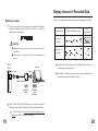
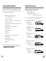
User’s Guide
Carefully read and fully understand
instructions before using this unit.
2002.04
16004104060
■ Notices about this User’s Guide
● Carefully read and fully understand these instructions before using this unit.
● All rights of this User’s Guide belong to T&D Corporation. It is prohibited to
use, duplicate and/or arrange a part or whole of this User’s Guide without
the permission of T&D Corporation.
● Please follow the safety precautions carefully. We cannot guarantee nor or
we responsible for safety if this product is used in any manner other than
was intended.
● T&D Corporation accepts no responsibility for any malfunction of and / or
trouble with this product or with your computer that is caused by the
improper handling of this product and will deem such trouble or malfunction
as falling outside the conditions for free repair of the attached warranty.
Safety Precautions and Instructions
In an attempt to ensure safe operation of our products and to protect them
from the possibility of damage throughout this User’s Guide the following
symbols are used to indicate important warnings, cautions and notices.
Please be sure to read, understand and follow the contents of all such
warnings.
■ Explanation of Warning Symbols
DANGER
These entries are actions that absolutely under
no circumstance should be taken. The taking of
such an action may cause serious personal
physical damage or death.
CAUTION
These entries are actions that if taken may lead
to physical injury or damage to persons or
things.
● T&D Corporation accepts no responsibility for any results or effects from
using this User’s Guide.
● This User’s Guide cannot be reissued, so please keep it in a safe place.
● On screen messages in this manual may vary slightly from the actual
messages.
● Figures and illustrations in this manual may be slightly simplified and may
differ from the actual product.
● Specifications, design and other contents are subject to change without
notice.
● Please notify the shop where you purchased this product or T&D
Corporation of any, mistakes, errors or unclarities in this manual.
● Microsoft , Windows and WindowsNT are registered trademarks of
Microsoft Corporation USA and are binding in the USA and all other
countries. Company names and product names are trademarks or
registered trademarks of each company.
● Teflon is a registered trademark of the Dupont Corporation and of the
Mitsui Dupont Fluro-chemical Corporation.
Published by T&D Corporation
1st Edition, April 2002
Copyright
1998-2002 T&D Corporation
All rights reserved.
1
■ Explanation of Picture Symbols
This symbol denotes an important warning or caution.
Inside or near the symbol will appear another symbol
giving details. (EX:
stands for INFLAMMABLE)
This symbol denotes a forbidden action. Inside or near the
symbol will appear another symbol giving details.
(EX:
stands for DO NOT TAKE APART)
This symbol denotes an action that you must take. Inside
or near the symbol will appear another symbol giving
details. (EX:
stands for BE SURE TO FOLLOW)
2
DANGER
Do not take apart, repair or modify the main unit.
It may cause fire, electrocution or damage. Please ask the shop
where you bought the product or T&D to carry out any repairs.
The Thermo Recorder is a device to measure temperature.
Do not use this unit for any purpose other than temperature
measurement.
If any smoke or strange smells are emitted from the unit,
immediately cease using it.
Continued use may cause fire, electrocution or damage.
Do not apply sensors to the human body.
If water or a foreign body enters the case, immediately cease
using it.
Continued use may cause fire, electrocution or damage.
D o n o t p u t yo u r fi n g e rs o r fo r e i g n m a t t e r i n t o t h e
Make sure to use only power sources compatible with this
unit.
The use of the wrong voltage may cause fire, electrocution or
damage.
Use these units under conditions with an ambient
temperature of -10 to 60℃ and humidity of 90%RH or less.
It is dangerous to swallow batteries.
Store all batteries, sensors and Thermo Recorder units out of the
reach of children.
This product has been designed for private or industrial use
only. It is not for use in situations where strict safety
precautions are necessary such as in connection with
medical equipment whether directly or indirectly.
We are not responsible for any malfunction or trouble
caused by the use of our product or by any problem caused
by the malfunction of our unit. Please be fully aware of this
before using our product.
3
CAUTION
communication port.
Do not use or store the unit in places such as listed below:
● In places exposed to splashing water.
● In the direct sun light or in excessively hot and humid
places.
● In excessively smoky, dusty, or steamy places.
● In areas exposed to harmful chemicals or gases.
● In areas exposed to strong magnetic fields.
Do not drop the unit, place heavy weight on the unit nor
expose the unit to a strong impact.
Doing so may cause damage to the unit.
4
CAUTION
Remove batteries from any unit that is not to be used for a
long period of time.
Batteries left in a unit not being used for a long time may leak
and cause a malfunction.
Battery life depends on the measurement environment,
communication frequency, recording interval and battery
quality.
Approximate battery life of 1 year is a standard of battery life
under use with a recording interval setting at 2 seconds or more
and in no way do we guarantee a battery’s life.
Recorded data and recording settings will be lost if the
batteries run out.
It is recommended that the batteries be replaced before they run
out.
Battery terminals may provide insufficient contact due to
age or vibration.
Please be careful not to lose data due to insufficient contact.
CAUTION
■ TR-0106, Standard Temperature Sensor of TR-71S
Use the sensor only within the measurable temperature
range (-40 to 110℃ ).
For extending the temperature sensor cable, use of only 1
extension cable is advised.
■ TR-3110, Standard Humidity Sensor of TR-72S
Use the sensor only within the measurable temperature
and humidity range (Temperature: 0 to 50℃ , Humidity: 10
to 95%RH).
The unit may give an error in humidity value if there is a
rapid change of temperature. However, the value will
return to normal after the sensor temperature stabilizes.
When the sensor is not used, put it in the attached plastic
bag with a drying agent and keep it in a cool, dark place at
5 to 25℃ and 30%RH or less.
An extension cable cannot be used with the Temperature/
Humidity Sensor.
5
6
Table of Contents
Introduction
Notices about this User’s Guide ................................ 1
Safety Precautions and Instructions .......................... 2
Table of Contents....................................................... 7
Getting Ready
Outline of the Product................................................ 8
Part Names and Functions ........................................ 9
Outline of the Product
■ Outline
Thermo Recorder TR-71S is a 2-channel data logger unit designed to
measure, display and record temperature. The TR-72S is a data logger
designed to measure, display and record temperature on 1 channel and
humidity on its other channel. The recorded data from either unit can be
downloaded to your computer via the included software "Thermo Recorder
for Windows" where you can use the software to create colorful graphs,
tables, export text files, as well manage files and control printing.
■ Contents of Package
Connect the Sensors ............................................... 10
Temperature and Humidity Sensors (TR-72S) ........ 11
Install Batteries and Turn Power On ........................ 12
Battery Life .............................................................. 13
TR-71S
TR-72S
Standard Temperature Sensors
(TR-0106) x 2
Temperature / Humidity Sensor
(TR-3110) x 1
LCD Display............................................................. 15
Basic Usage
Start Recording and
Set Recording Interval via Main Unit ....................... 16
Start Recording and
Set Recording Conditions via Computer ................. 18
● Accessories (Both TR-71S and TR-72S)
Display Amount of Recorded Data .......................... 20
Collecting Recorded Data........................................ 21
AAA Alkaline Batteries (LR03)
x2
Other
Optional Sensors List .............................................. 22
Communication Cable
(RS-232C : D-Sub 9Pin)
Cable Length 1.5m x 1
Copyright 1995-2002 TandD
Corporation. All rights reserved.
警告
Product Specifications ............................................. 25
Provisions for Free Repair ....................................... 26
7
このCD-ROMはパソコン用です 。
一般のオーディオ用CDプレーヤー
などでは絶対に再生しないでください。
聴覚の障害や、機器の故障などを
引き起こす恐れがあります。
for RTR-5,TR-5,TR-7,RTR-57C,TR-57C
DISC Ver.1.01
Standard Software
(Thermo Recorder for Windows)
x 1 set
User’s Guide and Warranty
Software User’s Guide
x 1 set
8
Connect the Sensors
■ Front View
Connecting the standard sensors to the main units.
Built-in Temperature Sensor (Channel 1)
▼
Part Names and Functions
Optional temperature sensors can be used. For details, see page 22
"Optional Sensors List".
■ TR-71S
Standard Temperature Sensors (TR-0106)
INTERVAL button
(Set Recording Interval)
REC/STOP button
(Start and Stop Recording)
Channel 1
Channel 2
Both are unconnected
Internal Sensor
―
Ch. 1 is connected
External Sensor
―
Ch. 2 is connected
Internal Sensor
External Sensor
Ch. 1 and 2 are connected
External Sensor
External Sensor
Connection condition
■ Left Side View
Sensor Connection Jack
(Channel 1)
Power Switch
Sensor Connection Jack
(Channel 2)
Available only for TR-71S
■ TR-72S
Standard Temperature/Humidity Sensor (TR-3110)
■ Right Side View
Communication Cable
Connection Jack
9
Connection condition
Channel 1
Channel 2
External (Temp.)
External (Humidity)
No external sensor connected
Internal (Temp.)
―
Temperature sensor connected
External (Temp.)
―
Temp/Humidity sensor connected
10
Temperature and Humidity Sensors
Install Batteries and Turn Power On
■ Battery Installation
Caution
● The replacement period for the standard sensor is 1 year. Replace it
when 1 year has passed after opening the bag. When using the
Temperature and Humidity Sensor, the surface can become dirty and
may decrease its sensitivity and accuracy. Therefore, if the unit is
being used in a dusty or smoky environment, it may be necessary to
change the sensor sooner than usual. The accuracy of the sensor
may decrease even within 1 year if it is used (kept) outside the
specified operation conditions.
1
Open the battery cover on the backside of the main unit. 。
2
Install 2 AAA-size alkaline batteries in the correct direction to align
+ and - .
Caution
● Install 2 new batteries. Avoid mixing old
and new batteries.
● Sometimes, after installing new batteries,
nothing will appear on the display for
about 3 seconds; this is not a malfunction.
● When the sensor is not used, put it in the attached plastic bag with a
drying agent and keep it in a cool, dark place at 5 to 25℃ and 30%RH
or less.
● Two types of sensor seals are pasted on the sensor. If the seal shows
abnormality (appears red), replace the sensor as soon as possible.
■ Sensor Seal Details
3
Close the battery cover.
■ Turn Power On
①
②
1
Turn ON the power switch on the left side of the unit.
① Water Leakage Sensor Seal
Normal (White)
Abnormal (Red))
The seal turns red in an abnormal state. This indicates that the sensor
has gotten wet.
Power Switch
ON
OFF
② Temperature Sensor Seal
Normal (White)
Abnormal (Red)
60
The seal turns red in an abnormal state and the figure 60 is displayed.
This indicates that the sensor was exposed to a temperature of 60℃ or
more.
11
● If during recording the switch is turned OFF, recording will stop
and all recorded data will be stored in the main unit.
12
Battery Life
1
Approximate time till [BAT] mark appears on the LCD display after
installing a new set of batteries is as follows:
- Recording interval of 2 sec. or longer
- Recording interval of 1 sec.
2
3
Approx. 10 months
Approx. 6 months
When the battery power becomes low, the [BAT] mark will appear on the
LCD display on the main unit. Once the [BAT] mark appears, you should
replace the batteries as soon as possible.
Continuing to use the unit with the [BAT] mark displayed and without
changing the batteries will cause the display to change to [SLP] and the
unit will enter sleep. Please change the batteries immediately.
● Recording stops and the recorded data and recording conditions are
stored in the main unit.
● Downloading data is only possible if you change the batteries.
● To start recording again after replacing the batteries you must reset
the Start Recording settings.
● While replacing the batteries the main unit will continue to function
● Recording will continue and the recorded data and recording
conditions will be stored in the main unit. You can still download the
data to your computer.
for up to 1 hour without batteries.
● From the time the unit enters sleep mode until battery power is
totally lost is about 1 year.
● Recording will continue while you replace the batteries.
● The main unit will remain operating without batteries during
replacement for up to 3 minutes.
● Continuing to use the unit without changing the batteries will cause it
to go into sleep mode. From the time the [BAT] mark appears to the
time the unit will go into sleep mode is roughly as below. Please
change the batteries before the unit goes into the sleep mode.
- Recording interval of 2 sec. or longer
- Recording interval of 1 sec
13
Approx. 3 months
Approx. 2 months
4
If left in sleep mode, the battery power will be lost and the display will turn
off.
● Recorded data and recording conditions will be lost from the main
unit.
● To start recording again after replacing the batteries you must reset
the Start Recording and Recording Conditions settings.
14
Start Recording and Set Recording
Interval via Main Unit
②
③
④
⑤
⑥
①
⑦
Recording can be started and interval settings made via the buttons on the
main unit.
▼
LCD Display
⑧
① Displays alternately channel number of present reading.
■ Start Recording
② Displayed during recording; flashes when waiting to star t
programmed recording.
CAUTION
● Once a new recording starts, all the recorded data in the main
unit is erased.
③ Indicates amount of data recorded.
④ Indicates communication is occurring with computer.
⑤ Indicates when measurement is above or below the limit.
▼ is displayed for -40 (-60)℃ or less, and ▲ for 110 (155)℃ or
more.
● Pressing the [REC/STOP] even during waiting for a programmed
start will start recording immediately.
1
※ Figures in ( ) show the usage of TR-71S wide range
temperature sensor.
⑧ Displays alternately Present Temperature or Humidity for each
channel.
15
Press the [REC/STOP] Button for more than 3 seconds or until "REC"
appears on the LCD and recording starts.
※ If the unit is set for Endless Method "LOOP" will be displayed on
the LCD before "REC" appears.
⑥ Indicates battery life warning; displayed when battery power
becomes low.
⑦ Displays unit of temperature. Can be changed between Celsius
and Fahrenheit via computer.
% (Humidity unit) display is only for TR-72S.
Only Recording Start/Stop and Recording Interval can be controlled by
using the main unit buttons. Other settings, such as Temperature Unit of
Display (C/F) and Recording Mode, can only be made via computer.
See page 18 "Start Recording and Set Recording Conditions via Computer"
for more details.
■ Stop Recording
1
Press down on the [REC/STOP] button until the "REC" mark
disappears from the display (about 3 seconds) and recording will be
stopped.
16
CAUTION
The Recording Interval cannot be set or changed during
recording and /or during wait for a programmed start.
1
Press down on the [INTERVAL] button for about 3 seconds or until the
measurement value display changes to the Recording Interval display.
Release the button.
EX: Recording interval is 15 seconds
Recording interval is 15 minutes
● If during recording or while waiting for a programmed
recording to start the [INTERVAL] button is pressed down for
3 seconds or more, the present recording interval setting will
be displayed. Upon releasing the button the measurement
display will return.
Start Recording and Recording Conditions can be set via your computer by
using the software "Thermo Recorder for Windows". The following settings
can also will be made:
▼
■ Set Recording Interval
Start Recording and Set Recording
Conditions via Computer
For more details, see the Thermo Recorder for Windows User’s
Manual or the "HELP" menu of the software.
■ Recording Start/Stop
Start and Stop the Recording via the Software.
CAUTION
By star ting a new recording or by making new recording
conditions, recorded data stored in the main unit will be erased.
Be sure to download and save any necessary recorded data left
in main unit before making new settings.
■ Set Recording Conditions
Recording Conditions such as "Record Star ting Date", "Interval",
"Recording Mode" and "Temperature Unit of Display(C/F)" can be set or
changed easily via your computer.
In "Recording Mode" you can select from two recording methods.
2
Select the desired recording interval by pressing the [INTERVAL]
button. The interval will change each time you press on the button.
3
● One Time Method
One Time Method: Recording stops when 8,000 data readings have
been recorded and "FULL" is indicated on the LCD. The estimated time
to reach "FULL" can be calculated with the following formula:
Stop pressing the button when the desired recording interval has been
reached.When the display returns to the measurement value display
the interval setting will be completed.
EX: A 30 second recording interval x 8,000 readings (Maximum
readings that the unit can record)
= 240,000 seconds =Approx. 2 days, 18 hours, and 40 minutes.
● Endless Loop Method
When 8,000 readings have been recorded the oldest data is overwritten
and recording continues.
17
18
Display Amount of Recorded Data
Amount of recorded data stored in the main unit will be displayed on the LCD.
■ Set Up Procedure
1
Connect the serial port of your computer and the main unit through the
standard communication cable. Connect the cable to a serial port
which has the following mark:
Recording Mode
As Recorded Data Increases
After
Reaching Max
One-time
Method
CAUTION
● Make sure to fully insert the connector to secure a proper
connection.
Endless Loop
Method
● Connecting to a wrong port will result in communication
failure.
TR-71S
TR-72S
Computer
Connect
Connect
● In One Time Method, the display will read [FULL] when it reaches
capacity and recording will stop.
● In Endless Loop Method, when it reaches capacity the indication will
remain the same but recording will continue.
Communication Cable
D-Sub9 Pin
Female
Open "Thermo Recorder for Windows" on your computer and make
settings such as "Start Recording" and other "Recording Conditions".
▼
2
19
D-Sub9 Pin
Male
(RS-232C)
For more details, see Thermo Recorder for Windows User’s
Manual or the "HELP" menu of the software.
20
Collecting Recorded Data
Optional Sensors List
With our exclusive software "Thermo Recorder for Windows" it is possible to
download all of the recorded data from TR-71S and TR-72S as well as carry
out the following functions in managing the data.
■ Temperature Sensors (for TR-7 Series)
-
Display 8 channels of data in colorful graphs
-
Control Display ON / OFF for each channel
-
Zoom in and out of graph data
-
D i s p l ay d a t a fo r t wo p o i n t s o n gra p h a n d d i f fe r e n c e s i n
measurements for those points
-
Select calculation range and calculate highest, lowest and average
▼
values for that range
-
Select and set precise recording start date and time
-
Change channel names
-
Change channel order
-
Merge channels
-
Delete channels
-
Change graph background color, line color and line width.
-
Create data tables
-
Print out graphs and tables
-
Create and export data in Text file format
-
Save data files
For more details about these functions and operation of the software , see
Thermo Recorder for Windows User’s Manual or the "HELP" menu of the
software.
Possible Measurement Range: -40 to 110℃
Sensor Temperature Durability: -50 to 115℃
Measurement Accuracy: Average ± 0.3℃(-20 to 80℃)
Average ± 0.5℃(-40 to -20 / 80 to 110℃)
Materials ① Thermistor ② TPE resin-shielded sensor ③ TPE resin-shielded wire ④ M3 Screw Hole
⑤ Compaction Tube ⑥ Stainless Pipe(SUS304) ⑦ Stainless Pipe(SUS316)
TR-0106 TPE resin-Shielded Sensor
All dimensions in mm
Cable Length: 0.6m
Thermal-Constant Time
In the Air: Approx. 75 Sec.
TR-0206 Stainless Protection Sensor
Cable Length: 0.6m
Thermal-Constant Time
In the Air: Approx. 75 Sec.
TR-0306 Stainless Protection Sensor
Cable Length: 0.6m
Thermal-Constant Time
In agitated water: Approx. 18 Sec.
※ Only stainless section is water resistant.
TR-0406 Stainless Protection Sensor
Cable Length: 0.6m
Thermal-Constant Time
In agitated water: Approx. 20 Sec.
※ Only stainless section is water resistant.
TR-0506 Stainless Protection Sensor
Cable Length: 0.6m
Thermal-Constant Time
In agitated water: Approx. 20 Sec.
※ Only stainless section is water resistant.
21
22
TR-0706 Stainless Protection Sensor
■Temperature and Humidity Sensors (for TR-72S/TR-72)
Cable Length: 0.6m
Thermal-Constant Time
In agitated water: Approx. 18 Sec.
※ Only stainless section is water resistant.
■ Wide Range Temperature Sensors (for TR-71S)
Humidity Measurement Range:
Temperature Measurement Range:
Sensor Durability Range:
Humidity Measurement Accuracy:
Service Life:
Operational Conditions:
CAUTION
These sensors cannot be used with TR-72S/TR-71/TR-72.
Possible Measurement Range:
Sensor Temperature Durability:
Water Resistant Ability:
Measurement Accuracy:
-60 to 155℃
-70 to 180℃
Splash Resistant
Average ± 0.5℃(-40 to 80℃)
Average ± 1.0℃(-60 to -40 / 80 to 100℃)
Average ± 2.0℃(100 to 155℃)
Materials ① Thermistor ② Stainless Pipe(SUS316) ③ Teflon Compaction Tube
④ Teflon Resin(FEP) Shielded
TR-1106 Teflon-Shielded Sensor
Cable Length: 0.6m
Thermal-Constant Time
In the Air: Approx. 15 Sec.
In agitated water: Approx. 2 Sec.
TR-1220 Stainless Protection Sensor
Cable Length: 2m
Thermal-Constant Time
In the Air: Approx. 36 Sec.
In agitated water: Approx. 7 Sec.
10 to 95%
0 to 50℃
-10 to 55℃
± 5%RH (at 25℃ and 50%RH)
1 year under normal conditions
No Dew Condensation or Water Leakage
No contact with organic solvents, solution or
gasses emitted from spoiled foods.
Materials ① Temperature / Humidity Sensor ② Polypropylene ③ Vinyl Chloride Coated Wire
TR-3110 Humidity and Temperature Sensor
All dimensions in mm
Cable Length: 1m
TR-3100 Humidity and Temperature Sensor
All dimensions in mm
■ Sensor Extension Cable
TR-1C30 Sensor Extension Cable
All dimensions in mm
Cable Length: 3m
Materials ① Vinyl Chloride Coated Wire
TR-1320 Stainless Protection Sensor
Cable Length: 2m
Thermal-Constant Time
In the Air: Approx. 12 Sec.
In agitated water: Approx. 2 Sec.
23
CAUTION
● Cannot be used with Temperature / Humidity sensor.
● Use only one extension cable per temperature sensor.
24
Product Specifications
Unit
Measurement Channel
Measurement Item
Internal Sensor
External Sensor
Optional Sensor
Measurement Accuracy
(Standard Sensor)
Measurement
Resolution Display
Sensor Materials
Provisions for Free Repair
TR-71S
TR-72S
2 Channel
(Select from Internal or External)
2 Channel
(Temperature and Humidity)
Temperature Only
Temperature
-10 to 60℃
-10 to 60℃
-40 to 110℃
-60 to 155℃
※1
-
0 to 50℃
-40 to 110℃
± 5% RH
(at 25℃ and 50%RH
0.1℃
1% RH
Thermistor
Polymer
8000 Readings × 2 Channels
AAA Alkaline Batteries x 2
Approximately 1 year ※ 2
Data Back-up
Low Battery Power/Switched OFF
Interface
Serial Communication (RS-232C)
Weight
Standard Sensors
※2
25
4
Free repair is not available in the following cases even though it is within
the warranty period:
(1) Trouble or damage was caused by careless operation, natural
disaster, fire, public pollution, or use of a power source other than
specified.
(2) If repair, adjustment, disassembly or modification of the unit has
been carried out by a person other than a T&D authorized engineer.
(3) Trouble or damage was caused by transportation, movement or
dropping of the unit after purchase.
Download at 9,600 bps (50 Sec./per Unit when data is full)
(4) Failure to submit the Warranty or failure to fill in all items required in
the Warranty.
H55mm x W88mm x D24mm
95g (Including AAA Alkaline Batteries x 2)
Temperature:-10 to 60℃
Humidity :Less than 90%RH (Without dew condensation)
TR-0106 x 2
TR-3110 x 1
AAA Alkaline Batteries (LR03) x 2
Accessories Communication Cable (RS-232C D-Sub9 pins cable length 1.5m) x 1
Standard Software x 1 set / User's Guide x 1 set
※1
If you have moved after purchasing, or the product was received as a gift,
or there are some difficulties contacting the shop from which you
purchased the unit, please contact us directly for service.
Endless Loop Method / One time Method
Battery
Temp. and Humidity
Durability of the Unit
3
Current Temperature, Recording Settings, Battery Life Warning,
Exceed Measurement Range Warning, Reading Capacity,
Unit of Temperature
Battery Life
Dimensions
If the customer requests free repair because of trouble within the warranty
period, bring or send the unit along with the warranty to the dealer. A
service charge may be added if a repairperson must be sent out to the
place of use for repair.
-
Average ± 0.3℃ (-20 to 80℃ )
Average ± 0.5℃ (-40 to -20 / 80 to 110℃ )
Recording Capacity
Communication Speed
2
10 to 95% RH
1.2.5.10.15.20.30 Seconds,
1.2.5.10.15.20.30.60 Minutes / Total of 15 choices
LCD Display
If the unit does not work properly despite the fact that the customer used
it properly and in line with the User's Guide, the unit shall be repaired free
of charge through the agent which sold the unit.
Humidity
Recording Intervals
Recording Mode
1
There are 2 types of temperature sensors covering different ranges for use with the
TR-71S. For details, see page 22 "Optional Sensors List".
Battery life differs depending on measurement environment and battery performance.
Changing the battery is possible even during recording.
5
The Warranty cannot be reissued.
This Warranty only promises customers free repair within the period and
conditions clarified in this Warranty. Therefore, the customer's legal rights will
not be limited by this Warranty. For further information on repair and others
service questions after the termination of the warranty period, contact your
dealer.
26
5652-169 Sasaga Matsumoto City NAGANO 399-0033 JAPAN
Phone:+81-263-27-2131 Facsimile:+81-263-26-4281
Homepage:http://www.tandd.co.jp/english/
E-Mail:[email protected]