1
WARRANTY
ONE YEAR LIMITED WARRANTY
USER’S GUIDE
HM Digital, Inc. ("the Company") products are warranted to the purchaser against defective
materials and workmanship for three (3) year from the date of purchase.
What is covered: Repair parts and labor, or replacement at the Company's option.
Transportation charges for repaired of new product to be returned to the purchaser.
What is not covered: Transportation charges for the defective product to be sent to the
Company. Any consequential damages, incidental damages, or incidental expenses, including
damages to property. This includes damages from abuse or improper maintenance such as
tampering, wear and tear, water damage, or any other physical damage. The Company's
products are not waterproof and should not be fully submerged in water. Products with any
evidence of such damage will not be repaired or replaced. See additional note below.
How to obtain warranty performance: Attach to the product your name, address, description
of problem, phone number, and proof of date of purchase, package and return to:
HM Digital, Inc.
5819 Uplander Way
Culver City, CA 90230
Implied Warranties: Any implied warranties, including implied warranties of merchantability and
fitness for a particular purpose, are limited in duration to five years from date of purchase. Some
states do not allow limitations on how long an implied warranty lasts, so the above limitation may
not apply to you. To the extent any provision of this warranty is prohibited by federal and state
law and cannot be preempted, it shall not be applicable. This warranty gives you specific legal
rights, and you may also have other rights, which vary from state to state.
NOTE: Warranties are product-specific. Third-party products and products deemed by HM
Digital as "accessories" are not covered under warranty. Third-party products include, but are
not limited to, batteries and fittings. Accessories include, but are not limited to, precipitator rods,
fuses and product cases.
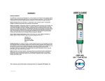
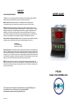
PS-200
DUAL TDS CONTROLLER
This manual and all information contained herein copyright HM Digital, Inc.
An extended version of this manual can be downloaded at
www.tdsmeter.com/products/usersguideps200.pdf
PS-200 05/05
INSTALLATION INSTRUCTIONS
OVERVIEW
Thank you for purchasing HM Digital’s PS-200. The PS-200 is a TDS (Total Dissolved Solids)
controller that monitors and controls the TDS levels of two water lines. If the TDS levels of the
output line (line 1) reach the user-determined set-point, the controller will send an analog signal
(via relay switch) to stop a valve or pump and sound an optional alarm.
CONTACT INFORMATION
If you have any problems or questions regarding your meter, please contact HM Digital, Inc.
HM Digital, Inc.
5819 Uplander Way
Culver City, CA 90230
[email protected]
www.tdsmeter.com
1-800-383-2777
SPECIFICATIONS
TDS Range: 0 - 999 ppm
Resolution: 1 ppm
Accuracy: +/- 2% F.S.
Temperature Compensation: Automatic (ATC) (1-65o Celsius)
Calibration: Manually adjustable (factory calibrated at 342 ppm NaCl)
Set-Point: Controlled by on-screen up/down buttons
Relay Control: The unit will send an analog signal to a pump/valve when the TDS levels reach
the set point (output line only)
Alarm: Optional steady beep (set by user)
Probe: ½” bushing, 3 meter (9.8 ft) shielded cable)
Display: Bright 5/8” L.E.D.
Power supply: AC 110V / AC 220V
Dimensions: 7.2 x 7.2 x 10.2 cm (2.8 x 2.8 x 4 in.)
Monitor Weight: 476 grams (1 lb .8 oz)
BOX CONTENTS
1. Controller
2. Sensor (2)
3. Sensor cable (gray) (2)
4. Power cord (black)
5. Mounting brackets
1. Remove the contents from the box.
2. View the diagram on the side of the controller.
3. Connect the black power cord to the outputs numbered 8 and 9. Screw in tight with a Phillips
head screwdriver. It does not matter which color wire is connected to the outputs. (Note – If in
the United States, connect the plug adapter to the power cord).
4. Connect a gray sensor cable by attaching the white wire to output #1, the red to #2 and the
black to #3. This is your output line (line 1). The output is the default reading.
5. Connect the second gray sensor cable by attaching the white wire to output #5, the red to
output #6, and the black to output #7. This is your input line (line 2).
6. Align the pins of each sensor to its cable and attach. Screw the tightening rings closed.
7. If the pump relay switch is already on, connect the pump relay cord (not included) to outputs
#13 and #14 only.
8. Insert the mounting brackets into the grooves on the bottom and top of the controller. Fasten
the brackets with the included screws.
9. Mount the controller to the panel.
10. Insert the sensor electrodes into ½” T-fittings, respectively for the output and input lines.
11. To DEACTIVATE the audible alarm, disconnect the wires from outputs #10 and #11.
12. Plug the power cord into an electrical outlet.
USAGE INSTRUCTIONS
1. The controller will turn on when the power cord is plugged into an electrical outlet.
2. Open the cover on the front of the controller by gently pulling down.
3. The controller comes factory calibrated to a 342 ppm NaCl solution. If you wish to recalibrate,
you can do so by inserting a screwdriver into the calibration trimmer pot. Turning clockwise will
increase the reading; turning counter-clockwise will decrease the reading.
4. To adjust the set point for the output line, press the ‘SET’ button. The reading will flash on the
display. Use the UP and DOWN buttons to adjust the reading. Pressing the button will advance
the reading by a single digit. Holding the button down will advance the reading quickly.
5. When the reading is at the desired set point, press the ‘SET’ button again. This will save the
set point.
6. If the TDS levels of the output line reach the saved set point, the controller will send an analog
signal (via a relay switch) to the pump or valve that is attached to inputs #12 and #13.
7. To turn off the audible alarm, disconnect a wire from inputs #10 or #11.
8. To monitor the TDS levels of the input line, press the ‘IN MODE’ button. This will switch the
display.
9. To turn off the controller, unplug it from the electrical outlet.
NOTE: It is advisable to test the set point and relay control prior to installing it on a water line.
Cleaning:
To clean the electrodes, use rubbing alcohol and a cotton swab. Lightly clean the electrodes.
Rinse with DI or distilled water. Air dry.
Electrode Replacement:
If your electrode has been damaged, you can purchase a new one without having to purchase a
new controller. Contact HM Digital or your authorized HM Digital distributor.
PS-200 05/05