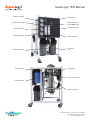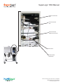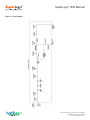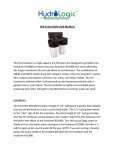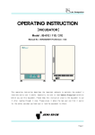
1
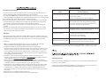
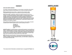
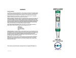
SuperLogic 1500
Installation and Operation Manual
370 Encinal Street, Suite 150, Santa Cruz, CA 95060
(888) 426-5644, Fax (831) 336-9840
www.hydrologicsystems.com
SuperLogic 1500 Manual
-
1,500 gpd system.
-
High flow, low energy membrane
-
Automated TDS controller and monitor with simultaneous feed and product
readout
-
Carbon fiber face plate
-
Rinsable sediment and
Eco-Green Carbon block prefiltration
-
Anti-scalant cartridge for use in hard water applications
-
Brine and product flowmeters
-
Prefilter In/Out gauges
-
Membrane In/Out gauges
-
Stainless steel waste water recirculation
valve
-
Stainless steel heavy duty commercial
pump
-
Low pressure cut-off switch
-
Non-petroleum bioplastic fittings
-
Manufactured in the USA
-
All systems QC tested and verified
370 Encinal Street, Suite 150, Santa Cruz, CA 95060
(888) 426-5644, Fax (831) 336-9840
www.hydrologicsystems.com
SuperLogic 1500 Manual
IntroducƟon
Congratula ons on the purchase of your SuperLogic commercial reverse osmosis system. This is professional water purifica on
equipment which, with proper care and maintenance can last you for many years.
Feed water condi ons can vary dras cally as well as fluctuate at your specific site. In order retain your warranty, the provided
opera ng log must be maintained and available for our review.
Prior to star ng up the SuperLogic reverse osmosis systems this user manual must be fully read and understood. Keep this
manual in a safe place for future reference. A copy of this manual can be found at www.hydrologicsystems.com.
System SpecificaƟons
HL Model Number
Feed Water and OperaƟng SpecificaƟons
31043
Capacity (gpd)1
1,500
Membrane Type
4” x 21” high flow,
low energy, thin-film
Number of Membranes
1
1
Membrane TDS RejecƟon
Prefilters
Pretreatment
Important Note: Feed water quality has a great effect on
the performance of your reverse osmosis. It is very important to meet the minimum feed water requirements.
Failure to do so will cause the membranes to foul and
void the warranty.
96%+
10” rinsable sediment (5 micron)
10” Green Carbon block (10 micron)
An -scalant cartridge
Feed Pressure
40-80 psi
Max OperaƟng Pressure
150 psi
Temperature
40° - 100°F
Pump
325 gph
Max Chlorine (conƟnuous)
<0.3 ppm
Motor
3/4 Hp
Max Total Dissolved Solids
5,000 ppm
Minimum Feed (GPM)
4 GPM
Hardness
<15 grains
Feed ConnecƟon
Female garden hose
Brine ConnecƟon
Product ConnecƟon
Dimensions
Weight
1
Silt Density Index
<5 SDI
3/8” tube
Turbidity
<1 NTU
3/8” tube
pH Range
2-11
18”W x 26”D x 30”H
100 lbs
Based on membrane performance aŌer 24 hours, 77°F (25°C), 500
ppm TDS, 120 psi and 66% recovery. Membrane performance may
vary ±15%.
Silica
< 1 ppm
Iron, Hydrogen Sulfide or
Manganese
Please Note:
0 ppm
Higher TDS and/or lower temperatures will reduce the
systems performance
Detailed water analysis available. All levels of pre and
post filtra on available to match source water.
Call HydroLogic directly for assistance (888) 426.5644
370 Encinal Street, Suite 150, Santa Cruz, CA 95060
(888) 426-5644, Fax (831) 336-9840
www.hydrologicsystems.com
SuperLogic 1500 Manual
Prefilter IN Gauge
Prefilter OUT Gauge
Vessel IN Gauge
Vessel Out Gauge
Sediment Prefilter
Solenoid Valve
TDS Monitor
Brine/Concentrate
Recircula on Valve
Product Flowmeter
Brine Flowmeter
An -Scalant
Pump/Motor
Low Pressure Switch
Carbon Prefilter
Membrane/Vessel
370 Encinal Street, Suite 150, Santa Cruz, CA 95060
(888) 426-5644, Fax (831) 336-9840
www.hydrologicsystems.com
SuperLogic 1500 Manual
Product Connec on
3/8”
Brine Connec on
3/8”
Feed Connec on
Garden Hose Thread
Flow Control
Product Water
Check Valve
370 Encinal Street, Suite 150, Santa Cruz, CA 95060
(888) 426-5644, Fax (831) 336-9840
www.hydrologicsystems.com
SuperLogic 1500 Manual
An -Scalant Cartridge: Allows the system to be operated at a 2:1 product to brine recovery ra o by preven ng membrane fouling
due to hardness in the feed water. The system can also be specified for a 4:1 product to brine ra o if a proper water so ener or
an scalant system is installed prior to the SuperLogic. Contact us for details @ (888) 426-5644.
Brine/Concentrate Recircula on Valve: A needle valve that controls the amount of brine from the membrane to be recirculated
back into the feed stream. This feature allows for higher recovery rates (lower waste water ra os). Addi onally, adjustment of
this valve regulates the pump discharge pressure.
Filter IN/OUT Pressure Gauges: Gauges that display the water pressure before and a er the sediment prefilter. Used to observe
the pressure drop through the sediment prefilter (a means of detec ng filter clogging or loading).
Flow Control: A fixed orifice that controls the amount of water flowing across the membrane to drain. This controls the ra o for
product water to waste water and either comes at a 4:1 or 2:1 ra o depending on how the system was specified.
Low Pressure Switch: An electrical switch that shuts off the unit in the event of low feed water pressure. This is used as a pump
protec on device. This is factory set to cut off at 12 psi (0.8 bar).
Membrane/Vessel (Desalinator): Separates dissolved solids from the feed water. This assembly consists of a stainless steel pressure vessel that houses the thin-film, reverse osmosis (RO) membrane.
Prefilter, Carbon: A 10 micron Eco-Green carbon block prefilter that removes chlorine prior to entering the membrane.
Prefilter, Sediment: A pleated filter that prevents undissolved par cles larger than 5 micron, from entering the system.
Product Water Check Valve: A one-way valve that prevents pressurized product water from flowing back into the desalinator
(and possibly damaging the membrane) when the system is off.
Pump/Motor: The rotary posi ve displacement pump boosts water pressure in the desalinator up to 150 psi (10.3 bar) for low
energy membranes to ensure high solids rejec on and high flow rates.
Solenoid Valve: Electrically operated valve that prevents water from flowing through the system when it is not in opera on.
Vessel Pressure IN/OUT Gauges: Gauges that display the opera ng pressure before and a er the RO membrane (used to observe
drop in membrane pressure indica ng fouling or clogging).
TDS Monitor: Simultaneously reports the feed and product water TDS in ppm. Includes op onal alarm func on. A low PPM limit
can be programmed so the system shuts down if PPM’s go above set point.
370 Encinal Street, Suite 150, Santa Cruz, CA 95060
(888) 426-5644, Fax (831) 336-9840
www.hydrologicsystems.com
SuperLogic 1500 Manual
Pre-InstallaƟon Procedures
PLEASE READ CAREFULLY. FAILURE TO FOLLOW THESE PROCEDURES CAN RESULT IN DAMAGE TO YOUR SYSTEM AND VOID YOUR
WARRANTY.
Packaging
Upon delivery, inspect packaging and report any damage to your carrier immediately. A er unpacking the system,
inspect it carefully for signs of damage. All damage claims should be made to the delivery carrier.
OperaƟng Parameters
The SuperLogic 1500 system may only be used on potable water. The user must be sure that water to be treated is both microbiologically safe and non-toxic. Ensure that the opera ng parameters outlined on page 3 are met at the installa on site. Items of most
importance are TDS, feed water pressure, flow rate, chlorine level and temperature range. A water analysis is helpful in determining
if any pre-treatment is needed. If your water analysis shows levels of substances in excess of the maximums, contact HydroLogic for
pre-treatment recommenda ons. Contact HydroLogic to inquire about a detailed water analysis.
InstallaƟon/Start up Procedure
PLEASE READ CAREFULLY. FAILURE TO FOLLOW THESE PROCEDURES CAN RESULT IN DAMAGE TO YOUR SYSTEM AND VOID YOUR
WARRANTY.
LocaƟon
Locate the system where it will be protected from harsh condi ons such as rain, snow, direct sunlight and extreme temperatures
(both hot and cold). The SuperLogic 1500 system can be located just about anywhere there is a water supply and electrical outlet.
This system is equipped with casters and may be rolled to different loca ons for opera on. Keep in mind, however, that the system
should be out of normal traffic pa erns yet accessible for daily monitoring and service.
Plumbing
(Figure 1 - Flow Diagram)
Always abide by local plumbing codes when installing the system.
Water Supply ConnecƟon
Connect feed water supply line to the female garden hose connector. Many other inlet fi ng op ons are available through HydroLogic. If the supply water is being drawn from a non-pressurized source (gravity feed), contact Hydrologic for addi onal informa on.
Minimum inlet pressure is 40 psi. If your inlet psi is below 40 contact HydroLogic for further informa on.
Drain ConnecƟon
Connect a 3/8” line from the quick connect elbow marked DRAIN to an appropriate drain point. A quick connect drain saddle is available as an op on from HydroLogic and can be plumbed directly into the main train of a sink. Be sure to check your local plumbing
codes to see if an air gap between the system and the drain is required.
Product ConnecƟon
The product water connec on to the storage tank should not be made un l the system is flushed and tested as outlined below.
Tank ConnecƟon (For Non-Pressurized Tanks Only)
When using a non-pressurized storage tank, connect the 3/8” tubing marked PRODUCT to the tank. Use an op onal electronic float
switch to shut down the system when the tank is full and start the system when water level is low. Quick connect bulk head fi ngs
are available to connect the product line to your tank. Contact HydroLogic for this and other op ons available.
7
370 Encinal Street, Suite 150, Santa Cruz, CA 95060
(888) 426-5644, Fax (831) 336-9840
www.hydrologicsystems.com
SuperLogic 1500 Manual
Figure 1 - Flow Diagram
370 Encinal Street, Suite 150, Santa Cruz, CA 95060
(888) 426-5644, Fax (831) 336-9840
www.hydrologicsystems.com
SuperLogic 1500 Manual
Electrical
(Figure 2 - Electrical Diagram)
WARNING! THE SYSTEM CAN START AT ANY TIME WHEN POWER IS CONNECTED. DO NOT CONNECT POWER UNTIL THE SYSTEM IS
COMPLETELY INSTALLED AND READY TO RUN.
The SuperLogic 1500 system is built with a standard 115v three-prong plug. Be sure the receptacle you use is on a circuit that
has a Ground Fault Interrupter (GFCI) and has sufficient capacity for the opera ng current as listed in the system specifica ons. It is
recommended that the system be installed on a dedicated circuit to prevent overloading on system start-up.
Op onal External Float Switch Wiring (For non-pressurized tanks only)
A piggy-back connector is supplied with the system. Please see addi onal installa on informa on included with the float switch.
Figure 2 - Electrical Diagram
370 Encinal Street, Suite 150, Santa Cruz, CA 95060
(888) 426-5644, Fax (831) 336-9840
www.hydrologicsystems.com
SuperLogic 1500 Manual
System Flush and Performance VerificaƟon
Although SuperLogic 1500 systems are fully tested at the factory prior to shipping, it is recommended to flush and verify your
system’s performance on-site.
Flushing
New membranes are shipped with a preserva ve that needs to be flushed out before use. Run the product line to drain while flushing the system.
•
•
•
•
•
•
•
Fully open the brine/concentrate recircula on valve by turning the knob counterclockwise.
Turn on water supply to the unit and check for leaks at the pre filter housings and the feed connec ons.
Plug the system into a compa ble electrical outlet. CAUTION! THE SYSTEM WILL START and rapidly cycle, star ng and stopping un l the membrane vessels are full of water and water starts flowing out of the product and brine ports.
A er the system has run for a few minutes to clear any air, turn the brine/concentrate recircula on valve clockwise
un l the “vessel in” pressure gauge reads 120 psi (8.3 bar).
Allow the system to flush for one hour with all water discharged to drain. Periodically check for leaks and
check the “vessel in” pressure gauge. It is likely that the vessel pressure will dri from 120 psi (8.3 bar) during the flushing.
If it does, turn brine/concentrate recircula on valve clockwise to increase pressure and counterclockwise to decrease
pressure.
The recircula on valve will need to be adjusted when membranes are replaced or if there are seasonal changes in water
temperature that cause the pump pressure to dri by 10 psi or more.
The 120 psi pressure provides the best compromise of membrane performance and life me while maintaining pump and
motor longevity. The system can operate above 120 psi and up to a maximum of 150 psi. Inlet water temperature and TDS
can effect the flow rate of purified water and in situa ons with low water temperatures and/or high TDS increased pressure
may be necessary to achieve desired flow rates of purified water.
*** DO NOT LET SYSTEM PRESSURE RISE ABOVE 150 PSI (10.3 BAR) AS DAMAGE TO THE SYSTEM CAN OCCUR***
Performance VerificaƟon
Factory test data is supplied with the system. To ensure op mal performance, on-site data should be taken and compared to the factory test data. This data should be taken a er the system has been flushed for one hour. Some devia ons may be seen due to
differences in feed water TDS and temperature between the site and factory. If you have already connected the product line to the
tank, you will need to disconnect it to take product samples.
Flow Tests
Determine the flow rates for both product and brine. Put the product line into a container and measure the volume of water that
flows into it in one minute. Repeat the process with the brine (drain) line. These values should be in either gallons per minute or
milliliters per minute. Product flow rates (at 77°F, 25°C) should be within 15% of the produc on rates given in the system specificaons.
Product to Brine/Concentrate RaƟo
Compute the product to brine ra o by dividing the brine flow rate by the product flow rate. This ra o should be either 4:1 or 2:1
± 30%. The 30% varia on can be due to inlet water temperature being above or below 77 degrees ferenheit as well as inlet TDS being above or below 500 PPM.
Total Dissolved Solids (TDS) rejecƟon
Using the TDS monitor, note the TDS in both the feed water and the product water.
Calculate percent rejec on using the formula: (Feed TDS-Product TDS) ÷ (Feed TDS) × 100 = % Rejec on
Rejec on should be 85% or be er. For example, where the feed TDS is 600 and the product TDS is 24, the
percent rejec on is: (600-24) ÷ 600 × 100 = 96%
370 Encinal Street, Suite 150, Santa Cruz, CA 95060
(888) 426-5644, Fax (831) 336-9840
www.hydrologicsystems.com
SuperLogic 1500 Manual
Low Pressure Switch Test
While the system is running, shut off the water supply to the system. The system should shut off. If the system does not shut off a er
ten seconds, either unplug the system or restore the water supply to the system. Call HydroLogic to diagnose problem.
DO NOT LET THE SYSTEM RUN WITHOUT THE WATER SUPPLY TURNED ON. PUMP DAMAGE WILL OCCUR.
Tank ConnecƟon
Make the tank connec on as outlined on page 8.
OpƟonal Float Switch Test (for non-pressurized tanks)
The system should run when the float is hanging down by the power cord. Tilt float up so the power cord is at the bo om of the
float. The unit should shut off. If unit does not shut off, re-check installa on procedure.
OperaƟon and Maintenance
SuperLogic 1500 systems are designed for simple opera on with li le user interven on. We recommend keeping accurate
performance records and following a regular preventa ve maintenance schedule to maximize the life of your system.
Daily System Checks
Your water supply pressure can vary from me to me. This can also affect your system opera ng pressure. Check
and adjust your vessel pressure daily to ensure maximum water produc on rates and quality. Check both the prefilter in pressure
gauge and pre filter out pressure gauge. Under normal condi ons, there should be a 3-5 psi difference
between the two gauges. When the difference reaches 10 psi it is recommended to change your pre-filters.
Monthly System Checks
In addi on to the daily checks, it is recommended to repeat the procedure in the sec on on Performance Verifica on
and record all data on a performance record sheet.
Semi-Annual Service
It is recommended to change both sediment and carbon filter cartridges at least every six months. Carbon cartridges
should be changed more o en if bad taste and/or odor becomes evident. Sediment cartridge should be changed more o en if water
supply pressure and filter pressure gauges differ by 10 psi or more.
Peripheral Equipment
Peripheral equipment such as tanks also have periodic maintenance requirements. It is essen al to maintain these as they can have a
drama c effect on the performance of your system. Refer to their specific manuals for proper maintenance procedures.
370 Encinal Street, Suite 150, Santa Cruz, CA 95060
(888) 426-5644, Fax (831) 336-9840
www.hydrologicsystems.com
SuperLogic 1500 Manual
Filter/Membrane Replacement Schedule
Sediment pre-filter - The 5 micron sediment filter is pleated and can be rinsed with a garden hose. You can rinse as o en as needed
but it is recommended to replace this filter every 6 months. If you observe a 10 psi drop in the pre-filter out gauge from the psi in the
pre-filter in gauge this indicates a clog in the sediment filter and you should either rinse it or replace it.
Carbon Pre-Filter - The 10 micron carbon filter is rated at 2 PPM chlorine removal and should be changed according to the schedule
below:
@ 4:1 ra o replace every 25,000 gallons of product water
@ 2:1 ra o replace every 15,000 gallons of product water
An -Scale Pre-Filter - Should be replace every me the carbon filter is replaced
Membrane - Upon startup the vessel in gauge should read 120 while the vessel out gauge will always read approximately 10 psi less
or 110 psi. When the vessel out gauge reads 20 psi lower than the vessel in gauge, or 100 psi, this indicates when to change your
membrane.
370 Encinal Street, Suite 150, Santa Cruz, CA 95060
(888) 426-5644, Fax (831) 336-9840
www.hydrologicsystems.com
Limited Warranty
This Limited Warranty extends to the original purchaser of the unit. This warranty covers all parts and factory labor needed to repair any manufacturer supplied item that proves to be defec ve material, workmanship or factory prepara on. The above-men oned warranty applies for the
first full calendar year from the date of purchase. These defec ve items are subject to the following exclusions: membranes, filters, O-rings, and
all other parts or components that require regular replacement as a result of ordinary usage.
Disclaimers: This Warranty applies only if the unit is installed and used in compliance with the instruc ons enclosed with the unit.
The Warranty does not cover any unauthorized parts or parts not included on the original unit. This Warranty does not cover the costs of repairs
or adjustments to the unit that may be needed because of the use of improper parts, equipment or materials. This Warranty does not cover
repairs required due to use of unauthorized parts, unauthorized altera ons of the unit, failure of a unit caused by such altera ons or by unauthorized repairs.
The Warranty does not cover malfunc ons of the unit due to tampering, misuse, altera on, lack of regular maintenance, misapplica on, fouling
due to hydrogen sulfide or iron, scaling from excessive hardness, or excessive membrane hydrolysis due to chlorine levels in excess of 1.0 mg/L,
or opera ng at too high a recovery. In addi on, damage to the unit due to fire, accident, negligence, act of god, or events beyond the control of
the manufacturer are not covered by this warranty.
The manufacturer warran es the membranes per the original manufacturers warranty. These warran es generally cover faulty material and
workmanship for anywhere from one to three years. Membrane fouling is not covered.
The manufacturer warran es all items supplied by outside vendors, per the manufacturers warran es. These warran es generally cover faulty
material and workmanship for one year.
Incidental and ConsequenƟal Damages: The manufacturer does not assume responsibility for payment of incidental damages as a result of the
failure of this unit to comply with express or implied warran es, such as lost me, inconvenience, damage to personal property, loss of revenue,
commercial losses, postage, travel, telephone expenditures, or other losses of this nature. Some states do not allow the exclusion or limita on of
incidental or consequen al damages, so this exclusion may not apply to you.
Owner’s Warranty ResponsibiliƟes: Under the provisions of this Warranty, the owner is expected to perform mely maintenance, as described
in this Manual. Neglect, improper maintenance, abuse, or unapproved modifica ons may invalidate the Warranty. Should your unit develop a
defect or otherwise fail to perform in accordance with this warranty, you should contact HydroLogic.
Implied WarranƟes: Implied at-law warran es of merchantability and fitness for a par cular purpose shall terminate on the date one year a er
the date of purchase. Note: some states do not allow limita ons on how an implied warranty lasts, so the above limita ons may not apply to you.
Other Rights This Warranty gives you specific legal rights and you may also have other rights that vary from state to state.
Returned Goods AuthorizaƟon In order to process a return, a Returned Goods Authoriza on (RGA) number will be assigned. Include the RGA
number with an explana on of the defect with the item being returned. Items returned under the RGA process will be reviewed and/or forwarded to the original manufacturer for evalua on. Items returned must be sent prepaid.
.
Date
PSI OUT
Filter
PSI IN
PPM
Feed
°F/°C
PPM
Product
GPM
PSI OUT
Vessel
PSI IN
GPM Recovery
Brine
Rejection
Comments
PANEL CUT-OUT DIAGRAM
USER’S GUIDE
2 11/16 in. (68 mm)
2 11/16 in. (68 mm)
1. Using a knife, cut the diagram out (cut on the outer part of the line).
2. Align the cut-out to your panel and draw cut marks.
3. Cut the hole in the panel to the precise dimensions of the cut-out:
2-11/16 in. x 2-11/16 in. (68 mm x 68 mm)
PS-200
--> See the installation section for complete instructions.
PANEL MOUNT DUAL TDS
CONTROLLER/MONITOR
CONTACT DIAGRAM
8
9
10
AC
11
12
ALARM
(BUZZ)
110-220V
13
N.C.
14
N.O.
RELAY (SWITCH)
SENSOR IN
SENSOR OUT
WHITE
RED
BLACK
1
2
3
WHITE
RED
BLACK
5
6
7
HM
D I G I T A L
®
4
Thank you for purchasing HM Digital’s PS-200. The PS-200 is a panel mount total dissolved solids (TDS)
controller that monitors and controls levels of TDS in water. The controller has a maximum set point to
help maintain a limit of TDS allowed in the product water, as well as a second sensor to monitor the TDS
level of the feed water. If the TDS level rises to the set point, the controller will activate a warning light,
sound an alarm (optional) and switch the dry contact position from the normal position (to operate a
valve, pump, etc.). Once the TDS level drops below the set point, this will deactivate the light and alarm
and switch the contacts back to the normal position (normally open or closed). NOTE: The IN mode &
sensor does not have an alarm nor control set point. It is a monitor only.
THIS PAGE INTENTIONALLY LEFT BLANK
CONTACT INFO
If you have any problems or questions regarding your controller, please contact HM Digital, Inc.
HM Digital, Inc.
5819 Uplander Way
Culver City, CA 90230
U.S.A
[email protected]
www.tdsmeter.com
1-800-383-2777
BOX CONTENTS
1. Controller
2. Two sensors (SP-1)
3. Two sensor cables (grey) 5. Mounting brackets
4. Power cord (black)
6. U.S. plug adapter
SPECIFICATIONS
TDS Range: 0 - 999 ppm (mg/L)
Resolution: 1 ppm
Accuracy: ±2% (of the reading)
Temperature Compensation: Automatic (ATC) (1-60oC)
Calibration: Manual by trimmer pot calibration screw
Set-Point: Single point, controlled by on-screen up/down buttons (to any point within the range)
Set-Point Relay: single, isolated, 2A, Max. 220V, resistive load 100,000 strokes
Relay Control (out sensor only): The unit will open or close a circuit via dry contacts when the
ppm level of the OUT sensor (aka product water) reaches or exceeds the control setting (simple
switch). It can be used to control a pump, solenoid valve or other device.
Relay Voltage: 5V (the connected device needs its own power source)
Alarm: Optional steady beep (set by user)
Probe: ½” NPTF bushing
Cable Length: 3 meter (9.8 ft) shielded cable
Display: Bright tri-color L.E.D.
Power Supply: 110V/230V, ±10% Vac; 50/60Hz
Enclosure: Front and back with ABS
Environment: -10 to 50oC (4 to 122oF); RH max 95% non-condensing
Dimensions: 7.2 x 7.2 x 10.2 cm (2.8 x 2.8 x 4 in.)
Monitor Weight: 476 grams (1 lb 0.8 oz)
2
7
WARRANTY
INSTALLATION INSTRUCTIONS
IMPORTANT: Double-check your contacts prior to connecting the controller to a
power source. Incorrect connections could result in shorting out the unit.
ONE YEAR LIMITED WARRANTY
The PS-200, including the controller and both sensors, is warranted by HM Digital, Inc.
("the Company") to the purchaser against defective materials and workmanship for
one (1) year from the date of purchase.
What is covered: Repair parts and labor, or replacement at the Company's option.
Transportation charges for repaired of new product to be returned to the purchaser.
What is not covered: Transportation charges for the defective product to be sent to
the Company. Any consequential damages, incidental damages, or incidental
expenses, including damages to property. This includes damages from abuse or
improper maintenance such as tampering, wear and tear, water damage, or any other
physical damage. The Company's products are not waterproof and should not be fully
submerged in water. Products with any evidence of such damage will not be repaired
or replaced. See additional note below.
How to obtain warranty performance: Attach to the product your name, address,
description of problem, phone number, and proof of date of purchase, package and
return to:
HM Digital, Inc.
ATTN: Returns
5819 Uplander Way
Culver City, CA 90230
U.S.A.
Implied Warranties: Any implied warranties, including implied warranties of
merchantability and fitness for a particular purpose, are limited in duration to five
years from date of purchase. Some states do not allow limitations on how long an
implied warranty lasts, so the above limitation may not apply to you. To the extent any
provision of this warranty is prohibited by federal and state law and cannot be
preempted, it shall not be applicable. This warranty gives you specific legal rights, and
you may also have other rights, which vary from state to state.
NOTE: Warranties are product-specific. Third-party products and products deemed by
HM Digital as "accessories" are not covered under warranty. Third-party products and
accessories include, but are not limited to, batteries, fuses, mounting brackets, plug
adaptors and fittings.
6
1. Remove the contents from the box.
2. Insert the controller into the panel. A square hole must be cut into the panel with dimensions
of 2-11/16 in. x 2-11/16 in. (68 mm x 68 mm). Page 8 includes a cut-out diagram.
3. Mount the controller to the panel by inserting the mounting brackets into the grooves on the
bottom and top of the controller. Fasten the brackets with the included screws.
4. View the contact diagram on the side of the controller (also on page 8).
5. Do NOT connect to a power source yet! Connect the black power cord to the contacts
#8 & #9 (110 V - 230V). It does not matter which color wire is connected to the
contacts. Screw in tight with a Phillips head screwdriver. (Note – If in the U.S. (or a country
that uses Type A or B plugs/sockets), connect the included plug adapter to the power cord).
6. If using a pump, valve, etc., connect a relay wire (not included) to contacts #13 and #14 for a
normally open (N.O.) position OR to contacts #12 and #13 for a normally closed (N.C.) position.
7. Connect a gray sensor cable by attaching the white wire to contact #1, the red to #2, and the
black to #3.
8. Connect the second sensor cable by attaching the white wire to contact #5, the red to #6, and
the black to #7. The cables are identical and can be swapped.
9. Align the pins of each sensor to each cable and attach. Screw the tightening ring closed. The
sensors are identical and can be swapped. Note which sensor is now the IN sensor and which is
the OUT sensor.
10. Insert each sensor electrode into a female ½” NPTF threaded fitting.
11. Attach the fitting connected to the OUT sensor to the product water.
12. Attach the fitting connected to the IN sensor to the feed water.
13. Ensure the orientation of the sensor is perpendicular to the flow of the water. Water
should flow equally over both pins. (If using a T, if you look through the top of the T, you
should see both pins equally side-by-side. If using the sensor in a tank, ensure that there are
no air bubbles trapped between the pins or in a fitting.)
14. To DISCONNECT the audible alarm, disconnect the blue wire from contacts #10 and #11.
15. Plug the power cord into an electrical outlet. The controller does not have a power switch
and will automatically power on when the power is connected.
USAGE INSTRUCTIONS
1. The controller will turn on when the power cord is plugged into an electrical outlet.
2. Open the cover on the front of the controller by gently pulling down.
3. There is only one display for both the IN mode (feed water) and OUT mode (product water).
The OUT mode is the default. To view the TDS level of the feed water, press the “IN MODE”
button. The display will switch to the feed water. NOTE: The display will automatically switch
back to the product water TDS after five seconds. To view the feed water display for longer,
press and hold the “IN MODE” button.
4. To turn off the controller, unplug it from the electrical outlet.
3
TROUBLESHOOTING
Setting the Control Set Point
1. To set the control set point (to activate a device via the relay), press the SET button once.
The EC reading will switch to a flashing number (the current set point).
2. Press the UP or DOWN buttons until the desired set point is reached. Pressing once will advance the reading by a single digit. Press and hold the button to advance the reading quickly.
3. Press the SET button again. This will save the set point to memory.
4. If the EC level reaches the saved set point, the controller will switch the contacts from the
normal position (either normally open or normally closed), thereby operating the pump,
solenoid valve, or other device attached to contacts #12 & 13 or #13 & 14.
5. Once the EC level falls below the set point, the contacts will switch back to the normal
position.
6. The alarm (if connected) will sound continuously while the EC level is over the set point.
The only way to turn it off is by lowering the EC level below the set point or disconnecting the blue wire from contacts #5 and #11.
Calibration
Your controller was factory calibrated to 342 ppm (NaCl). This level is suitable for most tap
water/filtered water applications, so it is ready to use out of the box. However, you may need
to re-calibrate based on your needs, as well as from time-to-time to ensure best results.
Problem
Potential Solution(s)
The controller will not power on.
1. Check to ensure the connections are correct (doublecheck 110V vs. 220V).
2. Check to ensure the power cable is plugged in.
Incorrect readings.
1. Try to recalibrate the controller. Note that the calibration should be done with a fitting on (if using a fitting).
2. Check for interference caused by other machinery or
electronics (near the controller or cables).
The relay control does not work.
1. Double-check the connections for contacts #12, 13 & 14.
2. Make sure that the set point is properly set.
The display shows “Err”.
1. The TDS level of the water is out of the controller’s range.
2. The sensor is not connected.
3. The sensor is dirty or damaged.
The display shows the feed water
TDS level, instead of the product.
1. The sensors are reversed. Connect the sensor for the
feed water to the IN sensor contacts, and the sensor for
the product water water to the IN sensor contacts.
To calibrate:
1. Obtain a certified calibration solution that is correct for your needs. The calibration
solution should be NaCl. HM Digital’s 342 ppm NaCl is recommended.
2. Calibrate to the OUT sensor. This will calibrate both sensors simultaneously.
3. Check the controller against the calibration solution. Prior to inserting the sensor into the
calibration solution, be sure the sensor is dry and free of any TDS residue. If the reading
on the controller does not match the calibration value, you will need to re-calibrate. If
using a fitting, calibrate with the fitting on the sensor. (See step 5 for additional information regarding the calibration value.)
4. For better accuracy, calibrate to a flowing solution. If this is not possible, you can
calibrate to a still solution. Ensure the fitting is completely filled with solution and there
are no air bubbles. This step is critical for proper calibration.
5. If the reading on the controller does not match the solution, adjust the reading up or
down by gently turning the trimmer pot calibration screw on the face of the unit (marked
as “ADJUST”) clockwise or counterclockwise to raise or lower the reading.
6. If calibrating to a still (not flowing) solution, calibrate to 3% above the level of the calibration solution. This will accomodate for the lack of flowing water, which the controller is
programmed for. For example, if the calibration solution is 342 ppm, adjust the screw
until it reads 352 ppm. If you are calibrating to a flowing solution, calibrate to the level of
the solution.
7. Gently release the screwdriver from the trimmer pot.
8. Your controller is now calibrated. There is no need to do anything else.
If troubleshooting does not solve the problem, please contact HM Digital for assistance. If your controller
is still under warranty, please return the controller to HM Digital for repair or replacement (see page 6).
Sensor Replacement
If your sensor has been damaged, you can purchase a new one (model SP-1) without the need
to purchase a new controller.
Contact your authorized HM Digital distributor for a replacement sensor. If you cannot locate
an HM Digital distributor, contact HM Digital at [email protected]