1
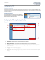
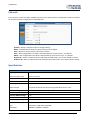
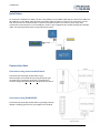
Thermocouple Interface User Guide Issue 1 30 June 2014 TC8 MANUAL This page is intentionally left blank Page | 2 30 June 2014 TC8 MANUAL Contents EC declaration of conformity ...................................................................................................... 4 Introduction ............................................................................................................................... 4 Key features ............................................................................................................................... 4 Standard inventory .................................................................................................................... 4 Optional accessories .................................................................................................................. 4 LED behaviour ............................................................................................................................ 4 Configuring the TC8 .................................................................................................................... 5 Hardware connection ..................................................................................................................................................... 5 Software connection ....................................................................................................................................................... 5 Configuring the TC8 using Racelogic Config ................................................................................. 5 General ........................................................................................................................................................................... 5 1. 2. 3. 4. 5. Connection ...........................................................................................................................................................................5 Module Information .............................................................................................................................................................5 Load/Save .............................................................................................................................................................................5 Language ..............................................................................................................................................................................5 Write to unit .........................................................................................................................................................................5 Settings ........................................................................................................................................................................... 6 1. 2. 3. 4. 5. 6. 7. Baud Rate .............................................................................................................................................................................6 Data Format .........................................................................................................................................................................6 Modes ..................................................................................................................................................................................6 Extended Identifiers .............................................................................................................................................................7 Conversion Identifiers ..........................................................................................................................................................7 Timer ....................................................................................................................................................................................7 Tx Count ...............................................................................................................................................................................7 Channels .................................................................................................................................... 8 Specifications ............................................................................................................................. 8 Installation ................................................................................................................................. 9 Connection data ......................................................................................................................... 9 Connection using screw terminal block .......................................................................................................................... 9 Connection using RLVBACS002 ....................................................................................................................................... 9 LEMO Connectors ......................................................................................................................................................... 10 25 Way D Type Female Connector ............................................................................................................................... 11 Upgrading the TC8 firmware ..................................................................................................... 11 Unit dimensions ....................................................................................................................... 12 Contact information ................................................................................................................. 12 Page | 3 30 June 2014 TC8 MANUAL EC declaration of conformity We declare that this product has been tested to and meet the requirements of: EC directive 2004/108/EC “Adapting to technical progress council directive 72/245/EEC relating to the radio interference (electromagnetic compatibility) of vehicles and amending directive 70/156/EEC on the approximation of the laws of the member states relating to the type-approval of motor vehicles and their trailers.” And has also been assessed, via Technical Construction File, by an independent DTI Competent Body and found to be in conformance with the essential requirements of: EC Directive 89/336/EEC (and amending directives) “Council Directive of 03 May 1989 on the approximation of the laws of the member states relating to electromagnetic compatibility.” DTI Competent Body responsible for issuing certificate of compliance: 3C Test Ltd, Silverstone Technology Park, Silverstone, Northants. NN12 8GX Introduction The RLVBTC8 8 Channel thermocouple interface module is designed for use with VBOX data logging systems. The module is configured via CAN through Racelogic Config software. Key features 8 * K-type thermocouple inputs Supports standard & extended CAN frames CAN data rate up to 1Mbit Standard inventory Description Product Code Thermocouple interface VBTC8 5W lemo plug – 5W lemo plug RLCAB006 Sub D terminal block with integrated Cold Junction Compensation. DE-PAD-OPT1 Optional accessories Description Product Code 2m Thermocouple extension with high accuracy dynamic CJC. RLVBACS002 Serial connection cable for firmware upgrades. RLVBCAB01 LED behaviour CN (CAN) Flashes Blue as the TC8 receives CAN data. SC (Serial) Flashes Green as the TC8 receives RS232 data. PR (Power) Solid Red as long as the TC8 is powered up. Page | 4 30 June 2014 TC8 MANUAL Configuring the TC8 Hardware connection Configuration of the TC8 is performed using Racelogic Config software. Using the supplied RLCAB001 cable, connect the serial port on the TC8 to the computers 9 way D serial port – this can be done via a serial > USB converter if required. Software connection Use the drop down list to select the correct COM port that the speed sensor is connected to. Click the connect button to enter the TC8 setup screen. Configuring the TC8 using Racelogic Config General 3 1 4 2 5 1. Connection - Selected com port, refresh and disconnect buttons. 2. Module Information – Serial number and installed firmware version of connected unit. 3. Load/Save - Load/Save settings from/into a Racelogic setting file (.RSF). This allows setups to be kept for future use. 4. Language - Select an operating language. 5. Write to unit - After making changes to setup, the write to unit button must be selected to upload settings. Page | 5 30 June 2014 TC8 MANUAL Settings 3 1 4 5 2 6 7 1. Baud Rate - Baud Rate sets the bit rate of the CAN messages (not the frequency at which the messages are sent). The range of values that can be entered is 0 to 65535 however only the values indicated in the Setup Parameters Table should be used. A value other than these will cause the module to change the Baud Rate value to 500kbit/s on the next power cycle. 2. Data Format - This option allows you to change the format in which data is transmitted in standalone mode. 3. Modes - In the settings tab, the user has the option to configure the TC8 into one of three CAN modes to suit different applications. Racelogic Polled This mode should be set if the module is to be used with a Racelogic VBOX. All the CAN parameters are set to work with the Racelogic VBOX CAN protocol. In this mode no other parameters need be set or indeed will have any effect. User Polled This mode allows a customer’s own data logging system to poll the module for data using the CAN bus. In this way, the output timing of the sensor can be synchronised with other CAN information. The following parameters are all used and so must be set: Baud rate (Selectable from 125kbit/s, 250kbit/s, 500kbit/s or 1Mbit/s) Extended Identifiers (OFF or ON) Request identifiers (Identifiers used to request data from the sensor) Response identifiers (Identifiers used to transmit data from the sensor) Timed In this mode the module will send CAN data at intervals determined by the Timer value. The following parameters are all used and so must be set: Timer (Time interval in milliseconds between output data) Baud rate (Selectable from 125kbit/s, 250kbit/s, 500kbit/s or 1Mbit/s) Extended Identifiers (OFF or ON) Response identifiers (Identifiers used to transmit data from the sensor) Page | 6 30 June 2014 TC8 MANUAL 4. Extended Identifiers - Extended Identifiers can be set either ON or OFF. If they are off the CAN identifier type will be standard (11 bit). If they are on the CAN identifier type will be extended (29 bit). The Standard Identifier type allows 2048 different CAN message identifiers or message “names”. The Extended Identifier type allows 436207616 different CAN message identifiers. The identifier type should be set to match the CAN data logging equipment that the module is connected to. Entering a value of “off”, “OFF” or “0” will turn Extended Identifiers off. Any non-zero value, “on” or “ON” will turn Extended Identifiers on. 5. Conversion Identifiers - The Conversion Identifier only has an effect in User Polled Mode. When the module receives this identifier with zero data bits it will sample its inputs. This is set as separate command to a data request identifier so that it gives the module time to make a data conversion before having to send the data on the CAN bus. 6. Timer - The timer value is in milliseconds (ms). A smaller value means data will be sent more frequently, a larger value means data will be sent less frequently. The range of values that can be entered is 0 to 65535 however the minimum value that should be entered is 10. Below this value data values may be repeated on successive cycles. If a value of 0 is entered the module will change it to 1 on the next power cycle. Frequency output can be calculated as follows: Freq = (1/Timer) * 1000 The Timer value for a required frequency can be calculated as follows: Timer = (1/Freq) * 1000 Some example Timer values are shown against the frequency output. Timer Value 10 [ms] Frequency 100 [Hz] 50 100 400 1000 20 10 2.5 1 7. Tx Count - This TX count is the number of CAN channels transmitted so for the TC8 this should be set to 8. Page | 7 30 June 2014 TC8 MANUAL Channels In this section, each of the eight available channels can be selected from a drop down list. When selected, the channels specific configuration will be displayed. Channel – Select a channel to view or change settings. Name – Editable field to allow the channel name to be changed. Units – Option to select Celsius, Fahrenheit or Kelvin. Scale – Non-configurable. This scale is determined by the choice of units. °C is default. Offset – Non-configurable. This offset is determined by the choice of units. °C is default. Request ID – Select a request ID to be used when the CAN mode is set to User Polled or Timed. Response ID - Select a response ID to be used when the CAN mode is set to User Polled or Timed. Specifications Specification Input Signals Thermocouple Type K -270°C to 1372°C Sample Rate 6Hz continual update Resolution 24 bit Accuracy Thermocouple CJC within 25 way D sub connector typically better that ± 0.3°C Isolation Voltage 1000 VDC to processor Over Voltage Protection ± 35 VDC Common Mode Voltage < 2V CMR (50/60)Hz > 92dB Power Supply Voltage +12 VDC (±10%) CAN Type Baud Rates Page | 8 CAN 2.0A or CAN 2.0B compatible 250Kbit/s, 500Kbit/s, 1Mbit/s 30 June 2014 TC8 MANUAL Installation To connect the module to a VBOX, use the 5 way LEMO to 5 way LEMO cable Plug one end of this cable into the CAN port on the VBOX; plug the other end of the cable into either connector 1 or connector 2 of the TC8. The function of connectors 1&2 on the thermocouple module is the same to allow daisy chain connection of other devices on to the CAN bus. Power is also supplied to the module through the CAN Bus cable. The example below shows a typical break test setup. Connection data Connection using screw terminal block 8 Channel thermocouple module with K-type thermocouples connected directly using 25 way D-type terminal block (supplied as standard). Terminal block contains integral CJC (Cold Junction Compensation) device. Connection using RLVBACS002 8 Channel thermocouple module with K-type high precision adapter including dynamic CJC (not supplied as standard). Page | 9 30 June 2014 TC8 MANUAL LEMO Connectors Pin numbering on LEMO socket connector Connector 1 – CAN/POWER IN Pin I/O Function 1 I/O Direct connection to Connector 2 pin 1 2 I/O Direct connection to Connector 2 pin 2 3 I/O CAN High 4 I/O CAN Low 5 O +12 V Power Chassis Ground Connector 2 – CAN OUT Pin I/O 1 I/O 2 I/O 3 I/O 4 I/O 5 O Chassis Connector 3 – RS232 Pin I/O 1 O 2 I 3 4 5 O Chassis Page | 10 Function Direct connection to Connector 1 pin 1 Direct connection to Connector 1 pin 2 CAN High CAN Low +12 V Power Ground Function TxD, Serial Data Transmit RxD, Serial Data Receive N/A N/A +12V Power Ground 30 June 2014 TC8 MANUAL 25 Way D Type Female Connector Pin Function Pin Function 1 A/D Channel 1 + 14 +Vbatt 2 A/D Channel 1 - 15 GND 3 A/D Channel 2 + 16 Isolated 5 Volt supply (+ve) 4 A/D Channel 2 - 17 Isolated 5 Volt supply (-ve) 5 A/D Channel 3 + 18 Isolated 12 Volt supply (+ve) 6 A/D Channel 3 - 19 Isolated 12 Volt supply (-ve) 7 A/D Channel 4 + 20 GND 8 A/D Channel 4 - 21 GND 9 A/D Channel 5 + 22 GND 10 A/D Channel 5 - 23 A/D Channel 8 - 11 A/D Channel 6 + 24 A/D Channel 8 + 12 A/D Channel 6 - 25 A/D Channel 7 - 13 A/D Channel 7 + Upgrading the TC8 firmware It is recommended to check the web site periodically for updates. To upgrade the TC8 firmware, download the following from the RL website. 1. The TC8 latest firmware file (.RUF extension file) 2. Racelogic Upgrader software Connect the TC8 to the PC via the supplied RLCAB001 serial cable, and apply power to the TC8. Double click on the .RUF upgrade file, which auto runs the Upgrader software. Ensure the correct COM port is selected in Racelogic Update software, then hit ‘upgrade to start the procedure. When this is complete, powering the TC8 off and back on will complete the process. Note: To confirm which COM port is assigned to the TC8, check device manager. Ensure that other software which may try and use the COM port communications, such as VBOX Tools, is closed. Page | 11 30 June 2014 TC8 MANUAL Unit dimensions Contact information Racelogic Ltd Unit 10 Swan Business Centre Osier Way Buckingham MK18 1TB UK Tel +44 (1280) 823803 Fax +44 (1280) 823595 Email: [email protected] Web: www.racelogic.co.uk Page | 12 30 June 2014