1
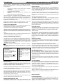
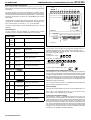
The power outputs are fitted with suppressors to protect against
electrical interference when switching off solenoid valves or contactors.
It is therefore essential to observe the output polarity. The line voltage
should be connected to the terminals marked LN and the switched
loads to LD.
N
LD1
LN1
LD2
IP5
LN2
LP210/220
E L N 14 13 12 11 10 9 8 7 6 5 4 3 2 1
The plant inputs are electrically isolated. Volt free contacts should be
connected for the logical conditions stated below. Note inputs 2 to 5
use a common input 14. Terminals 12, 11 & 8 must be linked.
SUPPRESSORS
The control supply neutral must be connected to terminal 1 for EMC
operation.
CE Conformance
This unit conforms with the relevant EU standards when installed
according to the JTL Installation Requirements for this product
IP4
IP3
C
L N
IP2
E
C
SUPPLY
IP1
Electrical Installation Requirements
Care should be taken to separate the power and signal cables to
prevent electrical interference and possible damage due to inadvertent
connection.
C
COMPRESSOR PACK SUCTION CONTROLLER TYPE:
IP2 - 5
JTL USER GUIDE
SUCTION
PRESSURE
CONTROL
DISPLAY
Jnet Zone
MU
SERIAL
PORT 15 16 17 18 19 20 21 22 23 24 25 26 27 28
1
2 LD1
3 LN1
Suppressed
High Suction Pressure (Alarm)
2
4 LD2
5 LN2
Suppressed
Watchdog
Jnet Zone
PLANT ZONE
Digital Output
PRESSURE
TRANSDUCERS
(4-20mA)
TEMPERATURE SENSORS
(5K THERMISTOR)
Doc 04289 ISS 1
Digital Inputs
1
12
13
Volt Free
Auto/Manual
2
10
14
Volt Free
High Discharge Pressure
3
9
14
Volt Free
Enable Optimisation
4
7
14
Volt Free
Low Liquid Level (LP220 only)
5
6
14
Volt Free
Low Oil Level (LP220 only)
The controller can be checked and the operation adjusted using a JTL
portable maintenance unit which plugs into the controller. Each
item of information has an item number. The more important items
are listed in the tables overleaf.
Examples:
To read item 21 press:
To set item 41 to &4.0 press:
To correct errors press:
To select next or previous items press:
and
Analogue INPUT (Pressure)
Analogue INPUT (Temperature)
Initial Commissioning and Bitswitch Settings
The controller has 3 sets of data built in to its program for use during
commissioning. These can be accessed by setting the virtual bitswitches
as shown in the table overleaf. The virtual bitswitches are set using item
966. Then set item 9 to 1234. This loads into the controller a suitable set
of data for the selected type of case. Adjustments should then be made
as necessary. The range over which the settings can be adjusted is also
defined by the bitswitch setting.
28
27
5k Thermistor
Suction Gas Temperature
If a JTL communications network is connected to the controller then
the unit number should be set on item 1.
26
25
5k Thermistor
Sensor 2
Pressure Display
The pressure can be displayed in psi, bar or kPa as selected by item 179.
24
23
5k Thermistor
Sensor 3
The LP210 & LP220 controller drives the JTL LCD14 display using a
CAB75 cable. Various cable lengths are available.
22
21
5k Thermistor
Sensor 4
20
19
5k Thermistor
Plant Room Temperature
18
17
+
-
4-20 mA
Suction Pressure
16
15
+
-
4-20 mA
Not used
Use of Maintenance Unit
Suction Pressure Control Strategy
The compressor capacity is controlled by measuring the suction gas
pressure (item21) and attempting to maintain this at a constant set
value within certain constraints. The suction pressure of the compressor
pack is controlled by varying the number of steps of compression. The
controllers can control an inverter trim compressor. When the inverter
trim control is available the inverter varies the compressor speed on the
trim machine to maintain the pressure. Only when the inverter driven
compressor is running at minimum or maximum speed will the other
compressors be stopped or started as required.
JTL USER GUIDE
COMPRESSOR PACK SUCTION CONTROLLER TYPE:
When a change in compressor capacity is required the controller
decides which step of capacity is to be changed. The decision is based
on the following:
•
•
•
•
•
The maximum number of starts per hour on an individual
compressor.
The compressor running hours are balanced.
All machines are run periodically.
Unnecessary starts and stops of the compressors are
avoided.
Capacity of compressors when unequal.
The suction pressure is maintained within the deadband if sufficient
capacity is available. The deadband is positioned symmetrically about
the suction pressure setpoint so that for example, if the setpoint is set
to 8 psi and the deadband is set to 4 psi, then the bottom of the
deadband is 6 psi and the top 10 psi.
Under normal conditions when the suction pressure is within the
deadband no increase or decrease in staged capacity will occur.
Suction Pressure Optimisation
When used in conjunction with a JTL suction pressure optimiser (SPO)
and appropriate JTL evaporator controllers/monitors, the
suction pressure can be optimised to save energy.
The optimiser monitors the evaporator conditions and sets the suction
pressure to the appropriate level to maintain the evaporator at the
optimiser level to achieve the desired temperatures at the lowest
energy.
The allowed range of pressure is set on items 40 (minimum) and 152
(maximum) optimisation is enabled on item 150.
CAPACITY CHANGES (STAGE CONTROL)
The stage control is implemented using additional digital interface (IF)
modules. One or two IF31 modules are used depending on the number
of compressors and stages on the compressors. Up to 8 stages can be
controlled using one IF31 module and up to 14 stages can be
controlled using IF31 modules.
Note when using two IF31 modules stages 1 -7 are on IF1 & 8-14 on IF2.
The output arrangement for multistage compressors is controlled
using item 167.
Compressor output
configuration
(Note: When compressor 1 is
set for 50% unloader then the
inverter is disabled)
0
1
2
3
When compressor 1 is not set
for inverter control all
compressors can be used for
stage control.
4
All compressors 1 stage
Compressor 2 50% unload
Compressors 2 & 3 50%
unload
Compressor 1 50% unload
Compressors 1 & 2 50%
unload
Compressors 1 to 3 50%
unload
5
LP210/220
longer the time before a capacity increase occurs.
Capacity Decrease
When the suction pressure goes below the control deadband the
controller program will decide when and how a decrease in capacity will
occur. If the pressure does not return within the deadband a change
in capacity will eventually occur.
As for the increase in capacity there is a minimum delay between each
decrease in capacity and the pressure error is integrated with respect
to time. When the integrated error is large enough a capacity decrease
will occur.
Capacity Decrease Response Time
The speed of response of the system can be adjusted using the
decrease time constant (item 45). The larger the time constant, the
longer the time before a capacity decrease occurs.
The use of separate increase and decrease time constants allows the
compressors to unload faster than loading if desired. This feature is of
particular benefit on low temperature stages to prevent the suction
pressure going too low.
Change Of Pressure
The change of pressure is also considered. If the pressure is going
towards the setpoint fast enough for the suction pressure to reach the
deadband in an acceptable time then, no capacity change is made.
Starts Per hour
Each compressor can be programmed to have a maximum number of
starts per hour. The item numbers for this selection are 219 for
compressor 1, 229 for compressor 2 up to 309 for compressor 10.
Once a compressor has started it is not allowed to restart again until the
restart timer, which ensures the starts per hour are observed, has
timed out.
Compressor Capacity
Each compressor can be programmed to have a capacity. The items for
this data are 216 for compressor 1, 226 for compressor 2 up to 306 for
compressor 10.
The capacity control takes account of the capacity that can be
started and stopped to ensure optimum control. Where a small
capacity change can be made by starting and stopping two machines
to give a net change in capacity this is done. In this condition the
machine to be started always starts before the machine to be stopped
regardless of whether capacity is to be increased or decreased.
High Discharge Pressure
If the discharge pressure exceeds the pressure safety level (on input 2)
then, the compressor capacity is reduced. There is a choice of two
actions in this condition on item 197 either the reduction in capacity is
controlled by the normal sequence of unloading or all conpressors are
stopped immediately.
When the pressure falls below the safety level the capacity is allowed to
increase again according to the normal requirements of the suction
pressure.
Capacity Increase
When the suction pressure goes above the control deadband the
controller will decide when and how an increase in capacity will occur.
If capacity is available and the pressure does not return within the
deadband a change in capacity will eventually occur.
Low load Condition
When the refrigeration load is low enough for the compressors to run
on 1 step only (including the trim compressor) then, to prevent the last
compressor stopping unnecessarily, the deadband lower limit is
automatically lowered, reducing the pressure at which the last
compressor would be stopped.
However, the capacity change does not occur immediately the pressure
goes outside the deadband. There is a minimum delay between each
increase in capacity regardless of demand.
In this condition the deadband lower limit is set to the 1st stage hold on
pressure setpoint (item 48).
The size and duration of the difference (or error) between the desired
pressure and the actual pressure is taken into account. This error is
integrated with respect to time. When the integrated error is large
enough a capacity increase will occur.
There is a very low suction pressure setting (item 196) below which, if
enabled by item 195, will stop all compressors instantly.
INVERTER CONTROL
To put this more simply, if the pressure error is large a capacity change
will occur more quickly than if the error is small.
Capacity Increase Response Time
The speed of response of the system can be adjusted using the
increase time constant (item 44). The larger the time constant, the
Inverter Speed Control
The inverter requires the use of an analogue interface module (IF35)
which can vary the frequency of the inverter drive is varied using a 0 10 signal. The inverter should be set up so that 0 V is for minimum
speed and 10 V is maximum speed.
Capacity Control
The controller starts and stops the inverter as required taking account
of any other compressors controlled by the same suction pressure. The
inverter automatically acts as a trim compressor and all the normal
compressor capacity control functions are operational. The capacity of
the compressor at minimum and maximum speed is programmed on
items 335 and 336.
Minimum Speed
When there are no other compressors running the inverter will stay on
at minimum speed until the minimum pressure set on item 341 is
achieved.
An input is available to monitor low liquid level in the receiver. The input
should be shorted out when there is no alarm condition. An alarm is
given after an adjustable delay (item 175) the contact is opened.
Low Oil Level (LP220 only)
An input is available to monitor low oil level in the system. The input
should be shortened only when there is no alarm condition. The alarm
is given 10 seconds after the input occurs.
Alarm Display
Various alarms are indicated on the pressure displays. Typical messages
displayed are:
P.FlC
Control Response
The controller uses proportional and integrated control algorithms to
control the inverter. These require speed gain (item 339) and time
constant (item 340) to adjust the response of the control of inverter.
Speed Output Limits
The speed output can be limited at both maximum and minimum
speed. The settings for the limits are item 342 for maximum and item
343 for minimum speed.
MAINTENANCE FACILITY
Forcing a Compressor to Run
A particular compressor may be forced to run by the maintenance unit
(MU) (items 217, 227 up to 307) for compressors 1 to 10 respectively.
Any compressor may be forced off by the maintenance unit (items 218,
228 up to 308) for compressors 1 to 10 respectively.
Resulting loading and unloading of the steps of the forced
compressor(s) follows all the normal rules specified above except that
the controller ignores the suction pressure on the forced
compressor(s).
Forced functions remain in operation for 30 minutes after the MU is
unplugged, after which time the controller will reset to normal control.
ALARMS
Compressor Faults
The individual compressors are continuously monitored. The state of
these inputs for compressor 1 is shown on item 213 of the
maintenance unit. Compressor 2 is on item 223 up to compressor 10
which is shown on item 503.
The state is indicated by the following messages:
rdy
O
=
=
ready to run (no faults)
not ready (fault)
If any compressor is not ready to run then this is indicated as a
compressor fault (item 97).
Pressure Alarms
The compressor suction pressure is constantly monitored and
compared with the high alarm level (item 42).
If the current suction pressure goes outside the set range for a short
time period then an alarm is given.
The time delay is achieved by integrating the difference between the
alarm level and the actual pressure over a period of 30 seconds. This
means that the larger the difference the faster the alarm occurs.
Pressure Transducer Alarm
The pressure transducer is constantly checked and if, after a 15 minute
time delay, the output goes outside the acceptable range an alarm is
given (item 91).
If there is a suction pressure transducer fault, the number of
compression steps is set to the maximum available. Control then
reverts to the compressor LP safety switches. All normal sequencing
restart delays, etc will be maintained in this mode of operation.
Low Liquid Level (LP220 only)
Hi.Sp
Hi.dP
Lo.Li
Cpr
Plant fault (auto input not present) - (highest
priority)
High suction pressure
High discharge pressure
Low level liquid
Compressor fault - (lowest priority)
The alarm conditions are flashed alternately with the pressure. In the
event of there being more than one alarm the highest priority alarm is
displayed
DAYLIGHT SAVING NETWORK
When connected to a JTL network this controller can operate by
displaying daylight saving time for its time and defrost schedule.
Daylight saving operation is selected by setting item 18. The connected
network controller then adjusts the times automatically during the
daylight saving period.
JTL USER GUIDE
COMPRESSOR PACK SUCTION CONTROLLER TYPE:
Function
Range
Units
40
150
152
43
44
45
48
195
196
197
Suction pressure setpoint (minimum)
Suction optimisation
Suction pressure (maximum)
Deadband
Increase time constant
Decrease
time constant
st
1 stage and fast unload set point
Low suction pressure safety
Low suction pressure safety level
Instant high discharge pressure shutdown
0 to 60, 100 to 200
0=Disabled 1=Enabled
5 to 60, 175 to 225
0 to 20
1 to 60
1 to 60
-8 to 60, 100 to 150
0=Disabled 1=Enabled
-5 to 40, 50 to 150
0=Disabled 1=Enabled
psi
42
41
High suction pressure
Low suction pressure
10 to 80, 200 to 300
-5 to 40, 100 to 150
psi
psi
121
421
426
Transducer
Transducer full scale (at 20mA)
Transducer zero scale (at 4mA)
0=Disabled 1=Enabled
50 to 200, 300 to 500
-15 to 0
psi
psi
200
205
208
Number of compressors
Maximum allowed to run
Minimum stop time
1 to 10
1 to 10
0 to 240
sec
2x5
2x6
2x0
Isolation
Capacity
Control
2X9
Starts per hours
0= not in use 1= in use
1-100
0= not stage controlled. 1= stage controlled,
2=2 stages (50/100% (compressor 1-3 only)
3=2 stages (66/100%)(compressors 1-3 only)
4= inverter control (compressor 1 only)
4- 20
psi
psi
psi
kW
Select
Minimum pressure
Time constant
Gain
Minimum steps
Maximum steps
Capacity at minimum speed
Capacity at maximum speed
0=Disabled 1=Enabled
-8 to 40, 100 to 150
1 - 240
1 - 250
1 - 63
64 - 127
1 - 100
1 - 100
DISPLAY
179
Display units
1 - psi, 2 - bar, 3- kPa
COMPRESSO
R ALARMS
206
158
175
Fault alarm delay
Fault alarm repeat delay
Low refrigerant alarm delay
0 - 10
00:01 - 24:00 (00:00 off)
15 - 240
JNET
FUNCTION
1
18
Unit number
Daylight saving operation
0.1 - 899.7
0= standard time, 1 daylight saving time
PLANT
INTERFACE
Note compressor 10 uses items 300-309
330
341
340
339
343
342
335
346
909
Interface communications speed
1=1200, 2=2400, 3=4800, 4=9600, 5=1920
966
Bitswitch Selection
0=Frozen Food (HFC) 1=Chilled (HFC)
2=Frozen Food (CO2)
Where 0-2 is the virtual bitswitch setting on item 966.
INVERTER
LP110
Item
VIRTUAL
BITSWITCH
COMPRESSORS (WHERE COMPRESSOR PRESSURE PRESSUR
x IS COMPRESSOR
COMMON
TRANSDUCE E ALARM
Pressure Control
ADJUSTABLE PARAMETERS
LP210/220
OTHER USEFUL ITEMS
psi
kW
kW
min
hr:min
min
JTL USER GUIDE
Item
21
146
151
153
191
181
182
201
202
203
COMPRESSOR PACK SUCTION CONTROLLER TYPE:
Function
PRESSURE
Pressure
Average pressure (1hr)
CONTROL
Optimised LT setpoint
Optimised HT setpoint
Integrated pressure error
Next increase site (kw)
Next decrease step (kw)
PACK DATA
No. of steps on load
No. of compressors running
Loaded capacity (kw)
LP210/220
Item
Function
Item
Function
2x3
2x2
37x
2x4
35x
COMPRESSOR DATA (WHERE x IS
COMPRESSOR NO.)
Status
Run hours (10 s of hours)
Run time (last 24 hours)
Restart timer
Starts per hour (last 24 hours)
345
346
331
332
333
INVERTER
Current proportional term
current integral term
Steps running
Run hours (10s of hours)
inverter/ compressor status
344
Capacity loaded
Note compressor 10 uses items
300-309, 360-380
Relay Output Rating
2A resistive
Applicable Documentation
Item Numbers
Firmware Variations
Doc No. 03731
Doc No. 03732
Connections Diagram
(LP210) Doc No. 03713
Supply Requirements
Installation Information
Doc No. 04257
Connections Diagram
(LP220) Doc No.03979
230 V ac 48-62 Hz Supply 6 VA maximum inputs
2 mA maximum
Output Configeration
Doc No. 03867
24 Vac (optional
Note: The information contained in this document applies to the
current version of the unit supplied with it. Full operating manuals,
item number and software variation information can be obtained
from the supplier JTL Systems.
This unit conforms with the relevant EU
standards when fitted in accordance with its
installation instructions.
PREDICT® is the patented JTL pattern recognition algorithm for
providing defrost on demand for the cabinets on a system.
LP110.wpd Issue 1 Feb 2014 Doc No. 04288
www.jtl.co.uk
JTL Systems Ltd . 41 Kingfisher Court . Hambridge Road . Newbury . Berks . RG14 5SJ Tel: (01635) 263646 Fax: (01635) 263647
JTL Help Desk Tel:08713157535