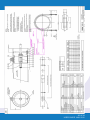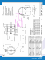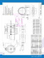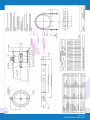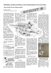
1
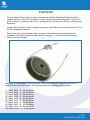
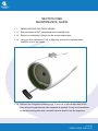
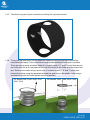
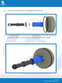
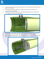
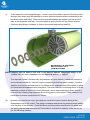
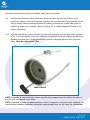
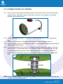
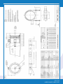
User’s Guide
8
to:
Phoenix Vessel Technology Limited
300, 450, 600 psi Side port pressure vessels
(1.5”, 2.0”, 2.5”, 76mm, 3.0”). Model numbers: 1908, 3342, 3348,
3648, 3649, 3312, 3605, 3603, 3641, 3615.
Phoenix Vessel Technology Limited
T: +44 (0) 1452 311673
F: +44 (0) 1452 310295
Unit 2, The Old Bakery, Lower Tuffley Lane, Gloucester GL2 5DP
E: [email protected]
www.phoenixvessel.co.uk
TABLE OF CONTENTS
FORWARD
SECTION 1 ‘Maintenance Guide’
1.1 Removing End Cap from Vessel
1.2 Component Disassemby
1.3 Component Assembly
1.4 Loading Membranes
1.5 Closing Vessel
3
4
4
7
9
12
16
SECTION 2 ‘Installation’
2.1 Handling
2.2 Vessel Support Position
2.3 Connections to Vessel
18
18
19
20
SECTION 3 ‘Operation’
3.1 Corrosion
3.2 Operating Conditions
3.3 Safety Precautions
21
21
22
23
SECTION 4 ‘Appendix’
4.1 Spare Parts List
4.2 Assembly Drawing 1908
4.3 Assembly Drawing 3648
4.4 Assembly Drawing 3649
4.5 Assembly Drawing 3342
4.6 Assembly Drawing 3348
4.2 Assembly Drawing 3312
4.3 Assembly Drawing 3605
4.4 Assembly Drawing 3603
4.5 Assembly Drawing 3641
4.6 Assembly Drawing 3615
24
24
25
26
27
28
29
30
31
32
33
34
1.5”, 2.0”
1.5”
2.5”
2.5”, 76mm
3.0”
1.5”, 2.0”
2.5”
3.0”
1.5”, 2.0”
1.5”, 2.0”
2 of 34
USER GUIDE MAY 2012
FORWARD
Phoenix Vessel Technology is a major manufacturer of Glass Reinforced Plastic Pressure
Vessels which are used as housings for reverse osmosis membrane elements. It is one of a
small number of companies with Code X accreditation of the American Society of Mechanical
Engineers.
Vessels are produced to cover a range of pressures upto 1200 psi and to house seven 40" or
five 60" membrane elements.
Each vessel has a documented history in terms of the manufacturing process and the
materials used. Before despatch, each vessel is tested to 1.1 times working pressure to
ensure structural integrity.
This User`s Guide applies to the series of 8” Side Ported pressure vessels which have a 1”
female product tube connection. The following Assembly Drawings are applicable :
(1) 1MNC 1908 - 8” 300 psi Model
(2) 1MNC 3648 - 8” 300 psi Model
(3) 1MNC 3649 - 8” 300 psi Model
(4) 1MNC 3342 - 8” 300 psi Model
(5) 1MNC 3348 - 8” 300 psi Model
(6) 1MNC 3312 - 8” 450 psi Model
(7) 1MNC 3605 - 8” 450 psi Model
(8) 1MNC 3603 - 8” 450 psi Model
(9) 1MNC 3641 - 8” 450 psi Model
(10) 1MNC 3615 - 8” 600 psi Model
3 of 34
USER GUIDE MAY 2012
SECTION ONE
MAINTENANCE GUIDE
1.1
REMOVING END CAP FROM VESSEL
1.1.1
Ensure system is NOT pressurised before starting work.
1.1.2
Remove connections if fitted from the central product port.
1.1.3
Using an 8mm hexagonal T bar or Allen key remove the caphead screw
located in end of the vessel.
1.1.4 Remove the 3 segment retaining rings .If removal is difficult then start at the
point where the gap between two segments is greatest. It may be of assistance
to tap the backing plate with a wooden hammer shaft to free the segments.
4 of 34
USER GUIDE MAY 2012
1.1.5 To remove the end cap will require an extractor. This is in three parts:
(1) PVC Connector - this is threaded to fit the vessel end cap.
(2) Bridge piece.
(3) PVC nut to apply extraction load.
Screw the PVC connector onto the product tube thread termination. Grasp the
remaining threaded portion of the connector (gloves or a cloth are recommended to
protect hands) and pull with a gentle rocking motion. 5 of 34
USER GUIDE MAY 2012
1.1.6 If the end cap cannot be removed as indicated above then slide the metal bridge over
the connector and use the PVC nut to apply extraction load.
6 of 34
USER GUIDE MAY 2012
1.2
COMPONENT DISASSEMBLY
1.2.1 With the end fitting extracted. Remove the adaptor from the end cap or from the end of
the element.
1.2.2 The hub to end cap joint should not be broken. However if there is evidence of leakage
of feed water into the product line then the hub may be removed from the end cap as
shown.
NOTE: Because of the tight fit removing the hub will result in damage to the pair of O-seals. Re
place as necessary.
7 of 34
USER GUIDE MAY 2012
1.2.3 The thrust ring can only be removed by undoing the cap head screws.
1.2.4
To remove the side port from the vessel the couplings must first be removed and the
manifold moved away. Then remove the clamp system holding the side port in position.
There are two versions as shown below.If a circlip is used (1.5” and 2” ports) then remove
the circlip with the tip if a screwdriver between the recess in the circlip and the body of the
port. Remove the circlip using a spirol twist. If a clamp is used (2.5” and 3” ports) then
release the clamp using the apprpriate screwdriver and remove the plastic collar using a screwdriver to prise the collar appart and out of position.
For Model 1908, 3648, 3649, 3312,
3641, 3615.
For Models: 3342, 3348, 3605, 3603
8 of 34
USER GUIDE MAY 2012
1.3
COMPONENT ASSEMBLY
1.3.1 Thoroughly clean all parts and check for the following.
(a) O-SEALS - cracked, worn or cut areas.
(b) SIDE PORT - corroded or distorted.
(c) END CAP - Cracks around centre 1” thread, 1” thread form damaged or truncated,
outer bearing edges worn, threads for M10 cap head screws damaged.
(d) SPIROLOC CIRCLIP - broken or distorted.
(e) Retaining Rings – Special Attention should be given to the GRP material. Any signs of wear or damage Replacement Required.
(f) CAP HEAD SCREWS - bent, corroded or threads damaged.
(g) ADAPTOR - cracks or scratches in sealing areas.
Components which show any of the above should be replaced.
1.3.2 CORROSION - Examine metal components for evidence of corrosion which might
affect structural performance.
NOTE: It is recommended that O-seals are replaced every time the end cap is rebuilt.
1.3.3.
Examine the sealing surface of the vessel side port. Remove any debris by flushing
with water or by using a clean cloth. Stubborn debris which adheres to the sealing
surfaces may be removed by lightly polishing with waterproof silicone carbide paper.
Use 400 Grade (fine) to start with and finish with 600 Grade (very fine). It will help to
moisten the grit paper with water during use. Afterwards remove any debris with water
or by using a clean cloth. Apply glycerine lubricant to vessel surfaces and fit the side
port into position using the insertion tool shown. This has a small lip on its outer edge
which pushes the seal into position without damaging it.
9 of 34
USER GUIDE MAY 2012
For Model 1908, 3648, 3649, 3312,
3641, 3615.
1.3.4
For Models: 3342, 3348, 3605, 3603
Push the side port fully home using the compression tool until the circlip groove emerges from the vessel port. Carefully fit the spiroloc circlip so that it does not distort (ie aim to fit
it into the victaulic groove first before engaging it into the circlip groove). Then winde
circlip into it’s finla positionposition.
For Model 1908, 3648, 3649, 3312,
3641, 3615.
For Models: 3342, 3348, 3605, 3603
NOTE: Lubricate the O-Seals with Glycerine. Do not use grease as this may impair the perfor
mance of the membrane elements.
10 of 34
USER GUIDE MAY 2012
1.3.5 Fit the O-seals into the grooves in the adaptor hub and end cap.
1.3.6 If the adaptor and hub was removed earlier then lubricate the O-seals with glycerine and push it into the end cap. It will help if the hub is twisted as it is pushed inwards.
11 of 34
USER GUIDE MAY 2012
1.4 LOADING MEMBRANES
This Section is provided as a Guide only, reference should be made to the element
manufacturers recommendations for loading.
1.4.1 UNLOADING MEMBRANE ELEMENTS
(a) Ensure system is NOT pressurised before starting work.
(b) Remove both end caps from vessel.
(c) Remove thrust ring and adaptors from vessel.
(d) Remove element from vessel following element manufacturers recommendations.
1.4.2 CHECKS BEFORE LOADING
(a)
Check the inside of the vessel for debris which may scratch the vessel. Remove any that is
found by flushing with water or by using a clean cloth. Stubborn debris which adheres to
the vessel may be removed by lightly polishing the area with waterproof silicone carbide
paper. Use 400 Grade (fine) to start with and finish with 600 Grade (very fine). It will help
to moisten the grit paper with water during use. Avoid continuously rubbing the same spot
in the same direction. Afterwards remove any debris with water or by using a clean cloth.
(b)
Check that there are no sharp edges to the membrane element which could scratch the
vessel. Contact the element manufacturer if these cannot be easily removed.
(c)
Check the element brine seal for wear and or cuts. Consult the element manufacturer for
spares and advice.
NOTE: Sharp debris may scratch vessel bore. This should be removed before unloading elements.
NOTE: Fine grade Scotchbrite may be substituted for waterproof silicone carbide paper.
1.4.3 LOADING MEMBRANE ELEMENTS
(a)
Lubricate the inside of the vessel with glycerine. If this is not available then flood vessel
with clean water.
(b)
Check with the element manufacturer concerning the position of the brine seal. Normally
this is placed on the upstream end of the element with the recessed part of the seal pointing
upstream.
(c)
Push the elements into the vessel from the upstream end.
12 of 34
USER GUIDE MAY 2012
(d)
(e) (f)
As each element is loaded insert the interconnector. To ease insertion glycerine should be
applied to the O-seals.
Care should be taken to ensure that the weight of the element is not taken on the
interconnectors during loading.
The final element should be inserted the following distances: MIN 10.8’’ (274mm) Max 11.7’’(297mm) in from the end of the vessel.
274 MM
UPSTREAM END
(g)
If the elements are pushed too far then continue pushing until the first element emerges
from the other end of the vessel. Take care to support its weight as it emerges.
(h)
Fit the adaptors provided with the vessel end cap to the core tube of the elements at both
ends
13 of 34
USER GUIDE MAY 2012
(i)
If the element is of the spigotted type - ie has a core tube which is proud of the face of the
element then shims may be required to ensure that the element remains connected to the
pressure vessel end fitting. These must be placed between the adaptor and the product
tube at the upstream end only - ie at the opposite end to the thrust ring. Shims may be
used with any design of adaptor to reduce movement and prolong seal life.
MAXIMUM OF 8 AT UPSTREAM
END OF VESSEL ONLY
(SHIM WIDTH 5MM)
NOTE: Adaptors must be fitted to both ends of the stack of elements. Catastrophic failure of the product line can occur if adaptors are not fitted and pressure is applied.
The required number of shims may vary between any two vessels loaded with elements due to tolerance build up, each will require measuring to find the exact number. The ideal situation is to have a working float of 5 to 10mm at the upstream end of the vessel to allow for future thermal expansion and contraction. The best method of achieving this is to fit the maximum number of shims (8 at 5mm thickness) and to keep subtracting shims one at a time until the retaining ring segments fit into the groove in the vessel. Finally subtract one more shim to ensure a safe float of 5-10mm.
(h)
Normally only one thrust ring is provided per vessel the correct location being at the
downstream end of the vessel. The design of adaptor and thrust ring ensures even loading over the face of the element. Push the thrust ring into position and secure it in place with the spring clip and cap head screws. Remember to include the washers under the nut as per the following drawing.
14 of 34
USER GUIDE MAY 2012
NOTE: Incorrect location of the thrust ring will damage the membrane elements.
NOTE: Please ensure the holes in the thrust ring are aligned with the ports in the vessel.
NOTE: Please ensure plastic screws in thrust ring are tightened sufficiently to avoid movement during operation.
15 of 34
USER GUIDE MAY 2012
1.5 CLOSING VESSEL
1.5.1
Check the inside of the vessel for debris which may scratch the vessel. Remove any that is found by flushing with water or by using a clean cloth. Stubborn debris which adheres to the vessel may be removed by lightly polishing the area with waterproof silicone carbide paper. Use 400 Grade (fine) to start with and finish with 600 Grade (very fine). It will help to moisten the grit paper with water during use. Avoid continiously rubbing the same spot in the same direction. Afterwards remove any debris with water or by using a clean cloth.
1.5.2 Lubricate the vessel inside surfaces with glycerine.
1.5.3 Lubricate the assembled end cap with glycerine, particularly the large 8” diameter O-seal.
1.5.4 Insert the end cap squarely into the vessel body sufficient to allow the segmented retain
ing rings to be inserted fully into the groove in the end of the vessel. If the end fitting is dif
ficult to push into the vessel then use the wooden shaft of a hammer to tap it into position.
NOTE: Fine grade Scotchbrite may be substituted for waterproof silicone carbide paper.
NOTE: Do not use excessive force to insert the end cap. A light tap is sufficient.
If the end cap cannot be easily inserted then the following checks should be carried out
(i) Lubricate vessel surfaces with more glycerine and try again.
(ii) The elements may have been pushed too far, proceed as follows:
Remove large 8” diameter seal from end cap.
Remove adaptor from element.
16 of 34
USER GUIDE MAY 2012
Remove small external O-seal from adaptor and insert into end cap.
(iii)
Without the O seals no effort should be required to insert the end cap, if there is still
insufficient space to insert the retaining rings then the elements have been pushed too far
during loading. Remove the last element by pushing it through the vessel taking care to
support its weight as it emerges. Refer to Section 1.4 `Loading Membrane Elements’ for
further information.
1.5.5
With the end fitting in place insert the two identical segments with the short sides together at the 12 o’clock position then fit the segment containing the hole by sliding downward and
between the other two. Fix with the caphead screw, by aligning with the hole in the end plate. Must be tightened to 8 Nm
8NM TORQUE
NOTE: Remember to refit all O-seals, thrust ring and insert adaptors into the central core tube of
the first and last element in the stack.
NOTE: A partially or badly assembled pressure vessel is dangerous. Carry out visual inspection on
vessel to check compliance with these instructions. Check working area for any items left unassembled
17 of 34
USER GUIDE MAY 2012
SECTION TWO
INSTALLATION
2.1
HANDLING
2.1.1 Vessels may be stored horizontally in any warehouse where the temperatures are as
follows:
Maximum 45o C (113o F)
Minimum 0o C ( 32o F)
2.1.2 DO NOT subject the vessel to sharp blows or impacts as this may damage the vessel wall.
2.1.3 DO NOT use the ports which project beyond the vessel as lifting or manoeuvring aids.
2.1.4 DO NOT scratch the vessel inside wall.
2.1.5 Slings wrapped around the vessel wall and suspended from the forks of a fork lift truck are safer and more stable than using forks alone.
2.1.6 Forks should always be padded before being brought into contact with any part of the vessel
body.
VESSEL DAMAGE
This should be reported to the shipping company and Phoenix Vessel Technology Limited.
18 of 34
USER GUIDE MAY 2012
2.2 VESSEL SUPPORT POSITION
The bending stresses generated in a long pressure vessel can be considerable and should not be
ignored. Careful choice of support position can minimise bending stresses to an acceptably low
level. Always follow instructions stated on the Assembly Drawing for each particular vessel design
and length ordered.
No. of 40’’
Elements
No. of
Supports
1
2
1.5
2
3
4
4.5
5
6
7
2
2
2
2
2
3
3
3
7.5
3
Distance rtween
Supports (mm)
Max
Min
740
500
1250
1750
2775
3190
3375
Distance between Outer
Supports (mm)
Max.
Min.
500
500
960
1970
2480
centre
support
3560
4020
6170
2990
3800
5090
6220
5330
19 of 34
USER GUIDE MAY 2012
2.3 CONNECTIONS TO VESSEL
2.3.1 Mount vessels using support saddles provided on horizontal surface at the recommended
support position and tighten straps to eliminate movement, do not tighten to more than drawing recommended torque.
2.3.2 Provide pressure relief device. This should be set to no more than 105% of design pres
sure.
2.3.3 Allow for an expansion of 0.5mm per metre length of vessel at design pressure.
2.3.4 Victaulic clamps used for connection to vessel should be assembled tightly with bolt pads of
clamp halves metal to metal.
2.3.5 It is recommended that two Victaulic couplings are used to connect the vessel to the mani
fold ie there is an intermediate pipe section between vesssel and manifold which can take up vessel or manifold movement. This intermediate pipe section should be at least 4” in length. The vessel thermal expansion is typically 25 x 10(exp-6) per C in the length direc
tion.
NOTE: Excessive torque applied to the straps may damage the vessel wall and cause the strap nut to seize onto the threaded portion.
20 of 34
USER GUIDE MAY 2012
SECTION THREE
OPERATION
3.1 CORROSION
- Operational pH level 3 - 10
- Cleaning only pH level 2 - 12 for no longer than 30 mins. Imediately clean down & purge.
Whilst every effort has been taken to ensure that end fittings have adequate corrosion resistance it
is the responsibility of the purchaser to assess that the materials offered are suitable for the specific corrosion environment.
Alternate materials are available with enhanced corrosion resistance, contact Phoenix Vessel
Technology Limited for advice.
End fittings should be maintained dry and free from corrosion. Vessel leaks should be investigated
and corrected.
21 of 34
USER GUIDE MAY 2012
3.2 OPERATING CONDITIONS
DESIGN SPECIFICATION
Internal Diameter:
To fit any 8” nominal diameter element.
Length:
Up to 300” of membrane elements.
Working Fluid:
Water (brackish).
Design Pressure:
300 psi (20.7bar).
Test Pressure:
1.1 times design pressure for upto 15 minutes maximum.
Design Temperature:
20 to 113o F (-7 to 45o C).
Expansion:
0.5 to 0.6 mm per metre length of vessel at design pressure.
Vacuum condition:
Down to -14.5 psi (0 bar absolute).
Support Position:
2 supports for 1 to 4.5 (40”) elements.
3 supports for 5 to 7.5 (40”) elements and any length supported outside of the recommended support range ( refer to `Vessel Support Position’
Section 2.2 this User`s Guide).
NOTE: The standard materials of construction may not be compatible with cleaning and preserving fluids. Alternative materials are available on request.
NOTE: The vessel should not be allowed to freeze solid. This will damage the vessel wall and make replacement necessary.
22 of 34
USER GUIDE MAY 2012
3.2 SAFETY PRECAUTIONS
Fibreglass reinforced pressure vessels will provide years of safe service if properly installed and
maintained. This section is for guidance only and should be used in conjunction with the
recommendations in the previous sections. Attention is drawn to the `NOTES:` located at the bottom of the page which highlight potential problems areas and safety recommendations.
3.2.1 Provide pressure relief device. This should be set to no more than 105% of design pressure.
3.2.2 Before pressurisation visually check that the segmented retaining rings are in position and
secured by the three cap head screws and that the backnut is fitted and is screwed up tightly.
3.2.3 DO NOT stand in line of end fitting while pressurisation takes place.
23 of 34
USER GUIDE MAY 2012
SECTION FOUR
APPENDIX
4.1 SPARE PARTS LIST
For part numbers and descriptions please refer to the relevant Technical Information Sheet.
24 of 34
USER GUIDE MAY 2012
25 of 34
USER GUIDE MAY 2012
26 of 34
USER GUIDE MAY 2012
27 of 34
USER GUIDE MAY 2012
28 of 34
USER GUIDE MAY 2012
29 of 34
USER GUIDE MAY 2012
30 of 34
USER GUIDE MAY 2012
31 of 34
USER GUIDE MAY 2012
32 of 34
USER GUIDE MAY 2012
33 of 34
USER GUIDE MAY 2012
34 of 34
USER GUIDE MAY 2012