1
PICDEM™ Z
DEMONSTRATION KIT
USER’S GUIDE
2004 Microchip Technology Inc.
DS51524A
Note the following details of the code protection feature on Microchip devices:
•
Microchip products meet the specification contained in their particular Microchip Data Sheet.
•
Microchip believes that its family of products is one of the most secure families of its kind on the market today, when used in the
intended manner and under normal conditions.
•
There are dishonest and possibly illegal methods used to breach the code protection feature. All of these methods, to our
knowledge, require using the Microchip products in a manner outside the operating specifications contained in Microchip’s Data
Sheets. Most likely, the person doing so is engaged in theft of intellectual property.
•
Microchip is willing to work with the customer who is concerned about the integrity of their code.
•
Neither Microchip nor any other semiconductor manufacturer can guarantee the security of their code. Code protection does not
mean that we are guaranteeing the product as “unbreakable.”
Code protection is constantly evolving. We at Microchip are committed to continuously improving the code protection features of our
products. Attempts to break Microchip’s code protection feature may be a violation of the Digital Millennium Copyright Act. If such acts
allow unauthorized access to your software or other copyrighted work, you may have a right to sue for relief under that Act.
Information contained in this publication regarding device
applications and the like is provided only for your convenience
and may be superseded by updates. It is your responsibility to
ensure that your application meets with your specifications.
MICROCHIP MAKES NO REPRESENTATIONS OR WARRANTIES OF ANY KIND WHETHER EXPRESS OR IMPLIED,
WRITTEN OR ORAL, STATUTORY OR OTHERWISE,
RELATED TO THE INFORMATION, INCLUDING BUT NOT
LIMITED TO ITS CONDITION, QUALITY, PERFORMANCE,
MERCHANTABILITY OR FITNESS FOR PURPOSE.
Microchip disclaims all liability arising from this information and
its use. Use of Microchip’s products as critical components in
life support systems is not authorized except with express
written approval by Microchip. No licenses are conveyed,
implicitly or otherwise, under any Microchip intellectual property
rights.
Trademarks
The Microchip name and logo, the Microchip logo, Accuron,
dsPIC, KEELOQ, microID, MPLAB, PIC, PICmicro, PICSTART,
PRO MATE, PowerSmart, rfPIC, and SmartShunt are
registered trademarks of Microchip Technology Incorporated
in the U.S.A. and other countries.
AmpLab, FilterLab, Migratable Memory, MXDEV, MXLAB,
PICMASTER, SEEVAL, SmartSensor and The Embedded
Control Solutions Company are registered trademarks of
Microchip Technology Incorporated in the U.S.A.
Analog-for-the-Digital Age, Application Maestro, dsPICDEM,
dsPICDEM.net, dsPICworks, ECAN, ECONOMONITOR,
FanSense, FlexROM, fuzzyLAB, In-Circuit Serial
Programming, ICSP, ICEPIC, MPASM, MPLIB, MPLINK,
MPSIM, PICkit, PICDEM, PICDEM.net, PICLAB, PICtail,
PowerCal, PowerInfo, PowerMate, PowerTool, rfLAB,
rfPICDEM, Select Mode, Smart Serial, SmartTel and Total
Endurance are trademarks of Microchip Technology
Incorporated in the U.S.A. and other countries.
SQTP is a service mark of Microchip Technology Incorporated
in the U.S.A.
All other trademarks mentioned herein are property of their
respective companies.
© 2004, Microchip Technology Incorporated, Printed in the
U.S.A., All Rights Reserved.
Printed on recycled paper. 11/12/04
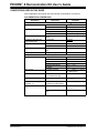
Microchip received ISO/TS-16949:2002 quality system certification for
its worldwide headquarters, design and wafer fabrication facilities in
Chandler and Tempe, Arizona and Mountain View, California in
October 2003. The Company’s quality system processes and
procedures are for its PICmicro® 8-bit MCUs, KEELOQ® code hopping
devices, Serial EEPROMs, microperipherals, nonvolatile memory and
analog products. In addition, Microchip’s quality system for the design
and manufacture of development systems is ISO 9001:2000 certified.
DS51524A-page ii
2004 Microchip Technology Inc.
PICDEM™ Z
DEMONSTRATION KIT
USER’S GUIDE
Table of Contents
Preface ........................................................................................................................... 1
Chapter 1. PICDEM Z Demonstration Kit Overview
1.1 Introduction ..................................................................................................... 5
1.2 What is the PICDEM Z Demonstration Kit? .................................................... 5
1.3 PICDEM Z Demonstration Kit Components ................................................... 5
1.4 Overview of the PICDEM Z Demonstration Kit ............................................... 6
1.5 PICDEM Z Motherboard ................................................................................. 6
1.6 PICDEM Z RF Card ........................................................................................ 8
1.7 PICDEM Z Software CD ................................................................................. 8
Chapter 2. Getting Started with the PICDEM Z Demonstration Kit
2.1 Introduction ..................................................................................................... 9
2.2 Host Computer Requirements ........................................................................ 9
2.3 Using the PICDEM Z Boards for the First Time ............................................. 9
2.3.1 Assembling PICDEM Z Nodes ........................................................ 9
2.3.2 Installing PICDEM Z Software Files .............................................. 10
2.4 Executing Preprogrammed Demo Applications ............................................ 11
Chapter 3. Experimenting with the PICDEM Z Demonstration Kit
3.1 Introduction ................................................................................................... 13
3.2 Modifying Demo Application Configurations ................................................. 13
3.2.1 Modifying Node ID Values ............................................................. 13
3.2.2 Modifying Association and Binding Configurations ........................ 15
3.2.3 Clearing Entire Neighbor and Binding Table ................................. 17
3.2.4 Clearing Individual Association and Binding Entry ........................ 18
3.3 Testing RF Performance .............................................................................. 19
3.4 Modifying the Hardware Configuration ......................................................... 20
3.5 Developing Your Application ........................................................................ 20
3.6 Creating Your Application Source File ......................................................... 20
3.6.1 Programming Your Application ...................................................... 20
3.6.2 Restoring Demo Firmware ............................................................. 21
Chapter 4. Troubleshooting
4.1 Introduction ................................................................................................... 23
4.2 Common Issues ........................................................................................... 23
2004 Microchip Technology Inc.
DS51524A-page iii
PICDEM™ Z Demonstration Kit User’s Guide
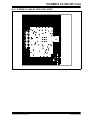
Appendix A. PICDEM Z Motherboard Schematics
A.1 PICDEM Z Motherboard .............................................................................. 25
A.2 PICDEM Z Motherboard Top Assembly ....................................................... 26
A.3 PICDEM Z Motherboard Layer 1 ................................................................. 27
A.4 PICDEM Z Motherboard Layer 2 ................................................................. 28
Appendix B. PICDEM Z 2.4 GHz RF Card
B.1 Introduction .................................................................................................. 31
B.2 What is the PICDEM Z 2.4 GHz RF Card? .................................................. 31
B.3 PICDEM Z 2.4 GHz RF Card Kit Components ............................................ 31
B.4 Overview of the PICDEM Z 2.4 GHz RF Card ............................................. 32
B.5 The PICDEM Z 2.4 GHz RF Card Features ................................................. 33
B.6 The PICDEM Z Software ............................................................................. 34
B.7 Getting Started with the PICDEM Z 2.4 GHz RF Card ............................... 34
B.7.1 Introduction ................................................................................... 34
B.7.2 Motherboard Requirements .......................................................... 34
B.7.3 Using the PICDEM Z 2.4 GHz RF Card for the First Time ............ 34
B.8 PICDEM Z 2.4 GHz RF Card Schematics ................................................... 35
B.9 PICDEM Z 2.4 GHz RF Card Top Assembly ............................................... 36
B.10 PICDEM Z 2.4 GHz RF Card PCB Layer 1 ................................................ 37
B.11 PICDEM Z 2.4 GHz RF Card PCB Layer 2 ................................................ 38
B.12 PICDEM Z 2.4 GHz RF Card PCB Layer 3 ................................................ 39
B.13 PICDEM Z 2.4 GHz RF Card PCB Layer 4 ................................................ 40
Worldwide Sales and Service .....................................................................................42
DS51524A-page iv
2004 Microchip Technology Inc.
PICDEM™ Z
DEMONSTRATION KIT
USER’S GUIDE
Preface
NOTICE TO CUSTOMERS
All documentation becomes dated, and this manual is no exception. Microchip tools and
documentation are constantly evolving to meet customer needs, so some actual dialogs
and/or tool descriptions may differ from those in this document. Please refer to our web site
(www.microchip.com) to obtain the latest documentation available.
Documents are identified with a “DS” number. This number is located on the bottom of each
page, in front of the page number. The numbering convention for the DS number is
“DSXXXXXA”, where “XXXXX” is the document number and “A” is the revision level of the
document.
For the most up-to-date information on development tools, see the MPLAB® IDE on-line help.
Select the Help menu, and then Topics to open a list of available on-line help files.
INTRODUCTION
This chapter contains general information that will be useful to know before using the
PICDEM Z Demo Kit. Items discussed in this chapter include:
•
•
•
•
•
•
•
Document Layout
Conventions Used in this Guide
Warranty Registration
Recommended Reading
The Microchip Web Site
Development Systems Customer Change Notification Service
Customer Support
DOCUMENT LAYOUT
This document describes how to use the PICDEM Z Demo Kit as a development tool
to evaluate and experiment with Microchip solutions for the ZigBee™ protocol. The
manual layout is as follows:
• Chapter 1: PICDEM Z Demonstration Kit Overview – Describes the PICDEM Z
Demonstration Kit and how it works.
• Chapter 2: Getting Started with the PICDEM Z Demonstration Kit – What you
need to know to start using the PICDEM Z Demonstration Kit.
• Chapter 3: Experimenting with the PICDEM Z Demonstration Kit – How to
program and use the PICDEM Z Demonstration Kit.
• Chapter 4: Troubleshooting – How to solve common operation problems with
the PICDEM Z Demo Kit.
• Appendix A: PICDEM Z Motherboard Schematics – Hardware information on
the PICDEM Z demonstration board
• Appendix B: PICDEM Z 2.4 GHz RF Card – Hardware information on the
PICDEM Z RF card
2004 Microchip Technology Inc.
DS51524A-page 1
PICDEM™ Z Demonstration Kit User’s Guide
CONVENTIONS USED IN THIS GUIDE
Where applicable, this manual uses the following documentation conventions:
DOCUMENTATION CONVENTIONS
Description
Arial font:
Italic characters
Initial caps
Quotes
Underlined, italic text with
right angle bracket
Bold characters
‘bnnnn
Text in angle brackets < >
Courier font:
Plain Courier
Italic Courier
0xnnnn
Square brackets [ ]
Curly brackets and pipe
character: { | }
Ellipses...
DS51524A-page 2
Represents
Examples
Referenced books
Emphasized text
A window
A dialog
A menu selection
A field name in a window or
dialog
A menu path
MPLAB® IDE User’s Guide
...is the only compiler...
the Output window
the Settings dialog
select Enable Programmer
“Save project before build”
A dialog button
A tab
A binary number where n is a
digit
A key on the keyboard
Click OK
Click the Power tab
‘b00100, ‘b10
File>Save
Press <Enter>, <F1>
Sample source code
Filenames
File paths
Keywords
Command-line options
Bit values
A variable argument
#define START
autoexec.bat
c:\mcc18\h
_asm, _endasm, static
-Opa+, -Opa0, 1
file.o, where file can be
any valid filename
A hexadecimal number where 0xFFFF, 0x007A
n is a hexadecimal digit
Optional arguments
mcc18 [options] file
[options]
Choice of mutually exclusive errorlevel {0|1}
arguments; an OR selection
Replaces repeated text
var_name [,
var_name...]
Represents code supplied by void main (void)
user
{ ...
}
2004 Microchip Technology Inc.
Preface
WARRANTY REGISTRATION
Please complete the enclosed Warranty Registration Card and mail it promptly.
Sending in the Warranty Registration Card entitles users to receive new product
updates. Interim software releases are available at the Microchip web site.
RECOMMENDED READING
This user's guide describes how to use the PICDEM Z Demo Kit. Other useful
documents are listed below. The following Microchip documents are available and
recommended as supplemental reference resources.
Microchip Stack for the ZigBee™ Protocol (AN965)
This application note describes how you can use the Microchip Stack for ZigBee
protocol to quickly build your application without the need to acquire detailed
knowledge of ZigBee specifications. To illustrate the usage of the stack, two working
demo applications are included. These demo applications can be used as a reference
or simply modified and adapted to your requirements.
THE MICROCHIP WEB SITE
Microchip provides online support via our web site at www.microchip.com. This web
site is used as a means to make files and information easily available to customers.
Accessible by using your favorite Internet browser, the web site contains the following
information:
• Product Support – Data sheets and errata, application notes and sample
programs, design resources, user’s guides and hardware support documents,
latest software releases and archived software
• General Technical Support – Frequently Asked Questions (FAQ), technical
support requests, online discussion groups, Microchip consultant program
member listing
• Business of Microchip – Product selector and ordering guides, latest Microchip
press releases, listing of seminars and events, listings of Microchip sales offices,
distributors and factory representatives
2004 Microchip Technology Inc.
DS51524A-page 3
PICDEM™ Z Demonstration Kit User’s Guide
DEVELOPMENT SYSTEMS CUSTOMER CHANGE NOTIFICATION SERVICE
Microchip’s customer notification service helps keep customers current on Microchip
products. Subscribers will receive e-mail notification whenever there are changes,
updates, revisions or errata related to a specified product family or development tool of
interest.
To register, access the Microchip web site at www.microchip.com, click on Customer
Change Notification and follow the registration instructions.
The Development Systems product group categories are:
• Compilers – The latest information on Microchip C compilers and other language
tools. These include the MPLAB C17, MPLAB C18 and MPLAB C30 C compilers;
MPASM™ and MPLAB ASM30 assemblers; MPLINK™ and MPLAB LINK30
object linkers; and MPLIB™ and MPLAB LIB30 object librarians.
• Emulators – The latest information on Microchip in-circuit emulators.This
includes the MPLAB ICE 2000 and MPLAB ICE 4000.
• In-Circuit Debuggers – The latest information on the Microchip in-circuit
debugger, MPLAB ICD 2.
• MPLAB IDE – The latest information on Microchip MPLAB IDE, the Windows®
Integrated Development Environment for development systems tools. This list is
focused on the MPLAB IDE, MPLAB SIM and MPLAB SIM30 simulators, MPLAB
IDE Project Manager and general editing and debugging features.
• Programmers – The latest information on Microchip programmers. These include
the MPLAB PM3 and PRO MATE® II device programmers and the PICSTART®
Plus and PICkit® 1 development programmer.
CUSTOMER SUPPORT
Users of Microchip products can receive assistance through several channels:
•
•
•
•
•
Distributor or Representative
Local Sales Office
Field Application Engineer (FAE)
Technical Support
Development Systems Information Line
Customers should contact their distributor, representative or field application engineer
(FAE) for support. Local sales offices are also available to help customers. A listing of
sales offices and locations is included in the back of this document.
Technical support is available through the web site at: http://support.microchip.com
In addition, there is a Development Systems Information Line which lists the latest
versions of Microchip's development systems software products. This line also
provides information on how customers can receive currently available upgrade kits.
The Development Systems Information Line numbers are:
1-800-755-2345 – United States and most of Canada
1-480-792-7302 – Other International Locations
DS51524A-page 4
2004 Microchip Technology Inc.
PICDEM™ Z
DEMONSTRATION KIT
USER’S GUIDE
Chapter 1. PICDEM Z Demonstration Kit Overview
1.1
INTRODUCTION
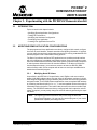
This chapter presents an overview of the features and requirements of the PICDEM Z
Demonstration Kit. Topics covered in this chapter include:
•
•
•
•
•
•
1.2
What is the PICDEM Z Demonstration Kit?
PICDEM Z Demonstration Kit Components
Overview of the PICDEM Z Demonstration Kit
PICDEM Z Motherboard
PICDEM Z RF Card
PICDEM Z Software CD
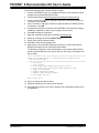
WHAT IS THE PICDEM Z DEMONSTRATION KIT?
The PICDEM Z Demonstration Kit is designed to allow developers to evaluate and
experiment with Microchip solutions for the ZigBee protocol. The PICDEM Z
Demonstration Kit provides two ZigBee nodes to create a simple two-node network. If
required, additional nodes may be purchased to expand the network. The
preprogrammed demo application firmware allows multiple operational configurations
without modifying a single line of code. Using the Microchip Stack for ZigBee Protocol
source code, available free-of-charge from the Microchip web site, developers can
develop their own applications or modify the supplied demo applications.
1.3
PICDEM Z DEMONSTRATION KIT COMPONENTS
Your demonstration kit contains the following items:
1.
2.
3.
4.
Two PICDEM Z demonstration motherboards.
Two PICDEM Z RF cards (Exact RF transceiver is dependent upon your kit P/N).
Two 9V batteries.
The Microchip Software CD for ZigBee CD-ROM, which contains demo
applications and source code for the Microchip Stack.
5. This manual (included on the CD-ROM in Adobe® Acrobat® format).
6. A warranty registration card.
2004 Microchip Technology Inc.
DS51524A-page 5
PICDEM™ Z Demonstration Kit User’s Guide
1.4
OVERVIEW OF THE PICDEM Z DEMONSTRATION KIT
The PICDEM Z Demonstration Kit (also referred to as the PICDEM Z kit) is designed
to demonstrate the Microchip solution for the ZigBee protocol. The PICDEM Z kit
includes two ZigBee nodes, each preprogrammed with demo Coordinator and
Reduced Function Device (RFD) applications. Each node consists of two boards – one
motherboard and one RF card. The PICDEM Z motherboard is designed to support
different types of RF transceivers. Microchip will be adding support for new RF
transceivers as time progresses. For the complete list of supported RF transceivers,
please visit the Microchip web site.
In addition to demonstrating standard ZigBee functionality, the PICDEM Z kit can also
be used to develop custom applications based on the ZigBee protocol. The kit includes
the complete source code for the Microchip Stack for the ZigBee protocol. The
Microchip application note AN965, Microchip Stack for the ZigBee™ Protocol
(DS00965) discusses the Microchip Stack in more detail.
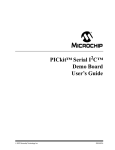
1.5
PICDEM Z MOTHERBOARD
The PICDEM Z demonstration board or motherboard, has all of the features necessary
to begin developing ZigBee protocol-based applications using the Microchip PIC18
family of microcontrollers. The preprogrammed firmware allows users to begin
evaluating the board right out of the box, with no additional programming or
configuration.
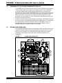
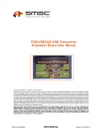
FIGURE 1-1:
PICDEM Z MOTHERBOARD
7
10
6
5
11
8
1
4
2
3
9
12
DS51524A-page 6
2004 Microchip Technology Inc.
PICDEM Z Demonstration Kit Overview
Features on the PICDEM Z demonstration board include:
1. Microcontroller Socket (U4): 40- and 28-pin DIP sockets are provided for the
user’s choice of Microchip PIC18 microcontrollers. The board is equipped from
the factory with a PIC18LF4620 high-performance microcontroller, clocked at
4 MHz and preprogrammed with the demo application firmware using the
Microchip Stack. The microcontroller on each board included in the
demonstration kit contains a label that identifies it as either a ZigBee Coordinator
or ZigBee RFD.
2. Temperature Sensor (U3: TC77): This is a 5-pin thermal sensor with an SPI
interface from Microchip.
3. User-defined LEDs (D1, D2): These two LEDs are driven by digital I/O pins of
the controller, and may be used to simulate a digital output to an embedded
device. These LEDs are enabled/disabled by jumpers JP2 and JP3. By default,
LEDs are enabled by permanently shorting jumpers via PCB traces. If required,
you may cut the traces and install your own jumpers.
4. User-defined Push Buttons (S2, S3): These switches are connected to digital
I/O pins on the controller, and may be used to simulate a digital input in an
embedded application. These switches do not have external pull-up resistors; as
a result you must enable the internal pull-up option on PORTB to correctly read
the switch status.
5. Reset Push Button (S1): This switch is tied to the MCLR pin on the controller,
and is used to reset the board.
6. RJ-11 (six-wire) Modular Connector (J5): This connector allows the
demonstration board to be connected to Microchip MPLAB ICD 2 systems for
advanced microcontroller debugging and programming.
7. RS-232 (DB9F) Connector (P1): This connector allows the demonstration board to
be connected to any other board or PC serial port. The preprogrammed demo
application firmware uses this connector to communicate with a PC and offer
application configuration options. If required, you may disconnect the on-board
RS-232 driver circuit from the controller by breaking the PCB traces on the J3 jumper.
8. RF Card Connector (J2): This is a common connector to connect all supported
RF cards. This connector provides +3.3V DC, an SPI bus, and a few discrete
digital I/O control signals.
9. Prototype Area: A prototype area is provided to breadboard additional circuitry
for development. Connections are provided for +3.3V DC, ground, and all I/O
ports of a microcontroller.
10. On-board Power: An on-board regulator provides 9V DC to 3.3V DC rated at
100 mA. The board may be powered via either an external 9V DC input (J1) or
the on-board 9V battery (B1). The board contains a diode to protect against an
accidental reverse power connection. When using a 9V battery to power the
board, switch S7 must be set to ON. The 2.5 mm 9V DC jack is wired such that
when a 9V DC plug is inserted, the on-board battery is automatically
disconnected from the circuit.
11. Measure Current (JP4): This jumper can be used to measure current drawn by
all of the circuits on the board. By default, this jumper is shorted via a PCB trace.
To measure the current, cut the JP4 trace and insert an ammeter between the
JP4 terminals. You may also install your choice of resistor at R9 and measure
voltage across it to determine the current.
12. Node ID: This unique serial number is used by the preprogrammed
demonstration application firmware to create a unique 64-bit extended Medium
Access Control (MAC) address. The extended MAC address of the board can be
changed by either serial configuration or by modifying firmware.
13. Revision Level Indicator (Back Side): The text on the solder side of the board
indicates the hardware revision level.
2004 Microchip Technology Inc.
DS51524A-page 7
PICDEM™ Z Demonstration Kit User’s Guide
1.6
PICDEM Z RF CARD
The PICDEM Z motherboard is designed to support RF cards using RF transceivers
from various vendors. Microchip is planning to add support for new RF transceivers.
Please check the Microchip web site for the list of supported RF transceivers. You may
find details of an individual RF card in its respective user’s guide document.
See Appendix B. “PICDEM Z 2.4 GHz RF Card” for information on the RF cards
supplied in your PICDEM Z Demonstration Kit.
1.7
PICDEM Z SOFTWARE CD
The CD provides the complete source code for the Microchip Stack for the ZigBee
protocol. It also includes two demo applications based on the Microchip Stack.
You may download the latest version of the Microchip Stack from the Application
Design Center at the Microchip web site.
DS51524A-page 8
2004 Microchip Technology Inc.
PICDEM™ Z
DEMONSTRATION KIT
USER’S GUIDE
Chapter 2. Getting Started with the PICDEM Z Demonstration Kit
2.1
INTRODUCTION
Topics covered in this chapter include:
• Host Computer Requirements
• Using the PICDEM Z Boards for the First Time
• Executing Preprogrammed Demo Applications
2.2
HOST COMPUTER REQUIREMENTS
The preprogrammed demo applications do not require the host computer to observe
the functionality. However, a host computer is required if you want to change the default
demo application configuration.
To change the default demo application configuration, you must have a system that
meets the following hardware and software requirements:
• Any computer system with one available standard serial port (DB9)
• Any operating system that provides a standard RS-232 terminal program using
the available hardware serial port
The PICDEM Z Demonstration Kit includes a CD that contains the complete source
code for both demo applications and the Microchip Stack. To view the contents of the
CD, modify demo applications or develop your own application, you must have a
system that meets Microchip MPLAB system requirements. Please visit the Microchip
web site for up-to-date system requirements and to download the Microchip MPLAB
software.
2.3
USING THE PICDEM Z BOARDS FOR THE FIRST TIME
2.3.1
Assembling PICDEM Z Nodes
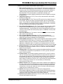
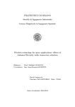
The PICDEM Z Demonstration Kit consists of two ZigBee node boards. Each node
consists of one motherboard and one RF card packaged separately. You must
assemble each node before applying power.
Perform the following steps to prepare each node:
1. Unbox and unwrap each board and place on a non-conductive surface.
2. Carefully plug the RF card into the J2 connector on the motherboard. Note that
the connectors on the motherboard and the RF card are polarized and will not
allow incorrect insertion.
3. If you have a 9V DC power supply with a 2.5 mm plug, power-up the board. If not,
connect one of the supplied 9V batteries to the BT1 connector and slide switch
S7 to the ON position. Observe that LEDs D1 and D2 have flashed. This confirms
that the boards are working properly.
2004 Microchip Technology Inc.
DS51524A-page 9
PICDEM™ Z Demonstration Kit User’s Guide
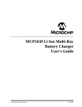
FIGURE 2-1:
2.3.2
MOTHERBOARD AND RF CARD CONNECTION
Installing PICDEM Z Software Files
The PICDEM Z Demonstration Kit contains the complete source code for the Microchip
Stack for the ZigBee protocol and demo applications. The Microchip Stack for the
ZigBee protocol is available free-of-charge to Microchip customers. As part of the
installation process, you must accept a no-cost electronic software license to continue
installation.
To install the files:
1. Insert the PICDEM Z software CD into your system’s CD-ROM drive.
2. Using Windows Explorer, open the CD and start the installation process by
double-clicking the MpZBeev1.00.00.exe icon. The version number may
change as new versions are made available.
3. When presented, review the software license agreement and click I accept to
accept the license agreement and continue the installation process. If you decide
to click I do not accept, the installation will terminate.
4. After successful completion, a new program group named “Microchip Stack for
ZigBee” will be created and all source files will be copied to the “MpZBee”
directory on the root drive of your computer. This program group provides
shortcuts for all of the documents.
DS51524A-page 10
2004 Microchip Technology Inc.
Getting Started with the PICDEM Z Demonstration Kit
2.4
EXECUTING PREPROGRAMMED DEMO APPLICATIONS
In order to observe full functionality of the demo applications, you must have one demo
Coordinator node and one demo RFD node with similar RF cards. As discussed later
in this document, you may reconfigure boards such that you may use more than one
RFD node.
The preprogrammed demo Coordinator and RFD applications implement a custom
remote control switch and LED application. For more information about these demo
applications, please refer to the Microchip application note AN965, Microchip Stack for
the ZigBee™ Protocol (DS00965).
The demo applications are completely stand-alone and do not require an interface to a
host computer. However, if you have access to a host computer, you may use it to
observe the activity logs of the applications. An interface to a host computer is useful
to understand and troubleshoot any setup issues you might have.
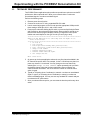
Do the following to execute a preprogrammed demo application:
1. Make sure that you have assembled each node by plugging the RF card into the
motherboard.
2. Remove power from both boards, if it was previously applied.
3. Locate the Coordinator node by looking for the “COORD…” label on the
controller.
4. Optional: Connect the Coordinator node to a PC serial port and launch your
favorite terminal program. Select the appropriate COM port and set it to 19200
bps, 8-N-1, no flow control.
5. Apply power to the Coordinator node. Observe that both D1 and D2 flash
simultaneously, followed by D2 flashing by itself. If connected to a PC, observe
that the terminal program displays the message “New network
successfully started”.
6. Now locate the RFD node by looking for the “RFD…” label on the controller.
7. Optional: Connect the RFD node to a PC serial port and launch your favorite
terminal program. Select the appropriate COM port and set it to 19200 bps,
8-N-1, no flow control.
8. While keeping the Coordinator node still powered, apply power to the RFD node.
Observe that both LEDs D1 and D2 flash simultaneously, followed by multiple
flashes of D2. If connected to a PC, observe that in one to two seconds, the
terminal program displays the message “Rejoin successful”. If you do not
see any message or see the message “Rejoin failed”, make sure that you
have the Coordinator node powered and running properly; reset the RFD node
and try again.
9. At this point, the RFD node has successfully associated with the Coordinator
node.
10. Press S2 on the RFD node and observe that D1 on the Coordinator node
switches on/off.
11. Press S2 on the Coordinator and observe that D1 on the RFD node switches
on/off. When you press S2 on the Coordinator, the D1 on the RFD node will toggle after few moments. This delay occurs due to the frequency at which the RFD
node polls the Coordinator node.
Note:
2004 Microchip Technology Inc.
The actual radio range for the PICDEM Z nodes depends on the type of RF
card and antenna in use. Please refer to the user’s guide of the respective
RF card for range information.
DS51524A-page 11
PICDEM™ Z Demonstration Kit User’s Guide
NOTES:
DS51524A-page 12
2004 Microchip Technology Inc.
PICDEM™ Z
DEMONSTRATION KIT
USER’S GUIDE
Chapter 3. Experimenting with the PICDEM Z Demonstration Kit
3.1
INTRODUCTION
Topics covered in this chapter include:
•
•
•
•
•
3.2
Modifying Demo Application Configurations
Testing RF Performance
Modifying the Hardware Configuration
Developing Your Application
Creating Your Application Source File
MODIFYING DEMO APPLICATION CONFIGURATIONS
The preprogrammed demo applications are factory configured with certain configurations such as node identifier, network association and binding information. If required,
you may easily change these configurations through a PC running a standard RS-232
terminal program or via a stand-alone binding process.
The Demo Coordinator and Demo RFD applications use a similar terminal interface
with minor differences in available configuration options. Some of the options require
the use of standard terminal software, while other options are performed by a sequence
of switch presses without the need for terminal software. To be able to perform the
terminal-dependent steps, you must have access to at least one RS-232 (DB9,
male-to-female) cable, a host computer with at least one serial port available and a
standard serial terminal program.
3.2.1
Modifying Node ID Values
As specified in the IEEE 802.15.4 specification, each ZigBee node must contain a
unique 64-bit MAC address value. One part of the 64-bit address consists of a 24-bit
IEEE assigned Organization Unique Identifier (OUI) and the other a 40-bit organization
assigned number. The PICDEM Z demo applications create a complete MAC address
by combining the Microchip OUI of 00-04-a3 and zero padded 16-bits of the node ID
value label found on the board. The node ID value is stored in the microcontroller Flash
memory. The PICDEM Z boards are factory-configured with their respective node ID
values. If required, you may easily change the node ID values by performing the steps
that follow.
Note:
2004 Microchip Technology Inc.
The following procedure assumes that you are using the Microsoft
HyperTerminal program. You may use any terminal program of your choice
provided the required port settings are set.
DS51524A-page 13
PICDEM™ Z Demonstration Kit User’s Guide
Perform the following steps to modify a Node ID value:
1. Connect a PICDEM Z node to an available serial port on the computer, using a
straight male-to-female DB9 RS-232 cable.
2. Launch HyperTerminal (Start>Programs>Accessories>Communications).
3. In the “Connection Description” dialog box, enter any convenient name for the
connection, then click OK.
4. In the “Connect To” dialog box, select the COM port that the PICDEM Z board is
connected to. Click OK.
5. Configure the serial port connected to the PICDEM Z node with these settings:
19200 bps, 8 data bits, 1 Stop bit, and no parity, no flow control
6. Click OK to initiate the connection.
7. Open the “Properties” dialog box by selecting File>Properties.
8. Select the “Settings” tab and click ASCII Setup….
9. Check “Echo typed characters locally”.
10. Click OK to close all open dialog boxes.
11. Apply power to the node while holding the S3 switch, or press and hold both
Reset and S3 switches; then release the Reset switch.
The following configuration menu would appear in the terminal window (Exact
header text would depend on the type of node you are trying to reconfigure and
date of build):
***************************************************************************
ZigBee Demo RFD Application v1.0 (Microchip Stack for ZigBee v1.0.0)
Built on Nov 11 2004
***************************************************************************
1. Set node ID...
2. Join a network.
3. Perform quick demo binding (Must perform #2 first)
4. Leave a previously joined network (Must perform #2 first)
5. Change to next channel.
6. Transmit unmodulated signal.
7. Transmit random modulated signal.
0. Save changes and exit.
Enter a menu choice:
12. Type 1 to change the Node ID value.
13. Follow the instructions to enter the Node ID value.
14. Press the Reset switch on the node or type 0 to exit configuration mode and run
the application.
DS51524A-page 14
2004 Microchip Technology Inc.
Experimenting with the PICDEM Z Demonstration Kit
3.2.2
Modifying Association and Binding Configurations
The PICDEM Z nodes are factory-configured with the following settings:
1. The demo RFD node is associated with the demo Coordinator node.
2. Switch S2 on the demo RFD node is bound to LED D1 on the demo Coordinator
node.
3. Switch S2 on the demo Coordinator node is bound to LED D1 on the demo RFD
node.
It is these configurations that allow you to press S2 on one node and control LED D1
on the other node. If required, you may easily modify these configurations using the
custom binding procedure implemented in the demo applications. For example, you
may bind S2 on RFD node to D1 on the same node or on another RFD node (assuming
that you have more than one RFD node).
Although the following procedure does not require a PC, you may use one to observe
the setup messages displayed by the demo applications. These messages are useful
to understand and troubleshoot setup issues. You may view the setup messages using
a terminal program set to 19200 bps, 8-N-1, no flow control.
Do the following to modify association and binding configurations:
1. Remove power from all nodes.
2. Apply power to the Coordinator node (a node with a “COORD…” label on its
controller) without pressing any switches, or if already powered, simply reset the
board by pressing the Reset switch. This puts the demo Coordinator node in the
normal mode of operation. Observe that D1 and D2 flash momentarily followed
by a brief flash of D2. If connected to a terminal program, note that the message
“New network successfully started” is displayed. If you see an error
message, it means that the demo Coordinator could not find an empty RF
channel.
3. While keeping the Coordinator node powered up, apply power to the RFD node
(a node with the “RFD…” label on its controller) while holding the S3 switch, or
press and hold both the Reset and S3 switches; then release the Reset switch.
Observe that D1 and D2 are on. If connected to a terminal program, note that the
configuration menu is displayed.
4. If you have more than one RFD node, you may continue step 3 for each RFD
node.
5. Press S2 on the RFD node to begin the association sequence with the
Coordinator. If connected to a terminal program, note that the message
“Successfully associated” is displayed. If you do not see this message,
make sure that the demo Coordinator node is powered and running in normal
mode. If your computer has two serial ports and the demo Coordinator node is
still connected to the computer, note that the terminal displays the message “A
new node has just joined”.
6. If you have more than one RFD node, press S2 on each RFD node to associate
them to the Coordinator node.
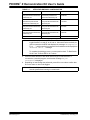
7. Since there are many different possible combinations of binding a configuration,
Table 3-1 is used to describe the necessary sequence of steps for each
combination:
2004 Microchip Technology Inc.
DS51524A-page 15
PICDEM™ Z Demonstration Kit User’s Guide
TABLE 3-1:
STEPS FOR BINDING A CONFIGURATION
To Bind Switch S2 On
To Bind LED D1 On
RFD: Press and hold S3 first Coordinator: Press and hold
then press S2 and release S2, S3 first then press S2 and
followed by S3
release S3, followed by S2
Coordinator: Press and hold
S3 first then press S2 and
release S2, followed by S3
Result
S3 on RFD is bound to D1 on
Coordinator
RFD: Press and hold S3 first S3 on Coordinator is bound to
then press S2 and release S3, D1 on RFD
followed by S2
RFD: Press and hold S3 first RFD: Press and hold S3 first S3 on RFD is bound to D1 on
then press S2 and release S2, then press S2 and release S3, same RFD
followed by S3
followed by S2
RFD1: Press and hold S3 first RFD2: Press and hold S3 first S3 on RFD #1 is bound to D1
then press S2 and release S2, then press S2 and release S3, on RFD #2
followed by S3
followed by S2
Coordinator: N/A
Note:
Coordinator: N/A
Not allowed
As each step is performed, LEDs D1 and D2 on the respective node will be
toggled between on and off, to off and on. Also note that the terminal program connected to the RFD node displays the message “Attempting to
bind...” and the terminal connected to the Coordinator node displays the
“Received valid...” message.
To complete the binding process, you must perform both “To Bind Switch
S2 On” and “To Bind LED D1 On” actions.
8. Press the Reset switch on each RFD node to begin normal execution. If
connected to a terminal program, note that the message “Rejoin
successful” is displayed.
9. Depending on how binding was performed, press S2 on one node to confirm that
D1 on the same or other node toggles.
Note:
DS51524A-page 16
To successfully control D1 on the same or other node, the Coordinator node
must be powered and running in normal mode.
2004 Microchip Technology Inc.
Experimenting with the PICDEM Z Demonstration Kit
3.2.3
Clearing Entire Neighbor and Binding Table
As specified in the ZigBee protocol specification, the Coordinator stores all association
and binding information in separate tables in its local memory. The Microchip demo
Coordinator application uses on-chip Flash memory to store this information.
You may either erase an individual association and binding entry or an entire table. To
erase the entire table on the demo Coordinator, perform the following steps:
1. Remove power from all nodes.
2. Connect the Coordinator node to a PC using a standard RS-232 cable.
3. Launch a terminal program on the PC and open the appropriate COM port with
these settings: 19200 bps, 8-N-1, and no flow control.
4. Apply power to the Coordinator node (the node with “COORD…” label on its
controller) while holding the S3 switch, or press and hold both the Reset and S3
switches, then release the Reset switch. Observe that D1 and D2 are on. Note
that the terminal program displays following configuration menu:
***************************************************************************
ZigBee Demo Coordinator Application v1.0 (Microchip Stack for ZigBee v1.0.0)
Built on Nov 11 2004
***************************************************************************
1. Set node ID...
2. Clear Neighbor Table.
3. Clear Binding Table.
4. Change to next channel.
5. Transmit unmodulated signal.
6. Transmit random modulated signal.
0. Save changes and exit.
Enter a menu choice:
5. To clear the association table, type 3. Upon successful completion, the
configuration menu will be redisplayed. Note that clearing the association table
automatically clears the associated binding table.
6. To clear the binding table, type 4. Upon successful completion, the configuration
menu will be redisplayed.
2004 Microchip Technology Inc.
DS51524A-page 17
PICDEM™ Z Demonstration Kit User’s Guide
3.2.4
Clearing Individual Association and Binding Entry
If you want to clear an individual table entry related to a specific RFD node, you must
execute a configuration command on that RFD node. To do this, perform the following
steps:
1. Remove power from all nodes.
2. Power-up the Coordinator node in normal mode and make sure that LEDs D1
and D2 flash once followed by a single flash of D2.
3. Select the RFD node whose association and binding entry needs to be cleared
and connect it to a PC using a standard RS-232 cable.
4. Launch a terminal program on the PC and open the appropriate COM port with
these settings: 19200 bps, 8-N-1 and no flow control.
5. Apply power to the RFD node while holding the S3 switch, or press and hold both
the Reset and S3 switches; then release the Reset switch. Observe that D1 and
D2 are on. Note that the terminal program displays the following configuration
menu:
***************************************************************************
ZigBee Demo RFD Application v1.0 (Microchip Stack for ZigBee v1.0.0)
Built on Nov 11 2004
***************************************************************************
1. Set node ID...
2. Join a network.
3. Perform quick demo binding (Must perform #2 first)
4. Leave a previously joined network (Must perform #2 first)
5. Change to next channel.
6. Transmit unmodulated signal.
7. Transmit random modulated signal.
0. Save changes and exit.
Enter a menu choice:
6. Type 2 to first join the already powered and running demo Coordinator node.
7. Type 4 to leave the already powered and running demo Coordinator node. Upon
successful completion, the configuration menu will be redisplayed. This step will
automatically remove all binding entries associated with this node.
Note:
DS51524A-page 18
After completing these steps, you must associate and bind this RFD node
with your choice of Coordinator to resume normal application operations.
Refer to Section 3.2.2 “Modifying Association and Binding
Configurations” for more information.
2004 Microchip Technology Inc.
Experimenting with the PICDEM Z Demonstration Kit
3.3
TESTING RF PERFORMANCE
The PICDEM Z demo applications also provide two special menu options to test the RF
performance. Menu options 6 and 7 allow you to transmit either a continuous
unmodulated signal or a random modulated signal.
Perform the following steps:
1. Remove power from all nodes.
2. Connect the node to a PC using a standard RS-232 cable.
3. Launch a terminal program on the PC and open the appropriate COM port with
these settings: 19200 bps, 8-N-1, and no flow control.
4. Power-up the node while holding the S3 switch, or press and hold both the Reset
and S3 switches, then release the Reset switch. Observe that D1 and D2 are on.
Note that the terminal program displays following configuration menu (Exact
header text would depend on the type of node you are trying to test):
***************************************************************************
ZigBee Demo RFD Application v1.0 (Microchip Stack for ZigBee v1.0.0)
Built on Nov 11 2004
***************************************************************************
1. Set node ID...
2. Join a network.
3. Perform quick demo binding (Must perform #2 first)
4. Leave a previously joined network (Must perform #2 first)
5. Change to next channel.
6. Transmit unmodulated signal.
7. Transmit random modulated signal.
0. Save changes and exit.
Enter a menu choice:
5. On power-up, the demo application selects the very first channel available in the
RF transceiver specific band. For example, for the 2.4 GHz frequency band, on
power-up, channel 11 is selected. You may change to the next channel by
selecting the “Change to next channel” option repeatedly until you reach
the desired channel. Note that the demo application does not display any
channel number information. You must count the number of times the menu
option is typed.
6. Type 6 (or 5 if testing demo Coordinator) to transmit a continuous unmodulated
signal, or type 7 (or 6 if testing demo Coordinator) to transmit a continuous
random modulated signal. You may now use any standard RF network analyzer
to evaluate the RF performance.
7. Once you select either test option, you must reset the board to perform any other
action.
2004 Microchip Technology Inc.
DS51524A-page 19
PICDEM™ Z Demonstration Kit User’s Guide
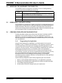
3.4
MODIFYING THE HARDWARE CONFIGURATION
The PICDEM Z boards are designed to be flexible in terms of enabling/disabling
on-board components and adding your own circuit.
3.5
Jumper
Purpose
J2
To connect/disconnect on-board RS-232 driver to PICmicro (RC7 and RC6 are
shorted via PCB trace to RX and TX respectively)
JP2
To enable/disable D1 LED (Factory enabled by PCB trace shorts)
JP3
Enable/Disable D2 LED (Factory enabled by PCB trace shorts)
JP4
To measure current draw of entire board (Factory shorted via PCB trace)
DEVELOPING YOUR APPLICATION
The PICDEM Z kit is shipped with complete source files for the Microchip Stack for the
ZigBee protocol. Please refer to the Microchip application note AN965 (DS00965) for
detailed information. Microchip is committed to continually improve and add new
features to the existing version of the Microchip Stack. Please check the Microchip web
site for the latest revision of the Microchip Stack source files.
3.6
CREATING YOUR APPLICATION SOURCE FILE
The Microchip Stack includes source files for both the demo Coordinator and RFD
applications. You may either modify one of the demo applications to suit your
application or use them as a reference to create your application. Please refer to the
Microchip application note AN965 (DS00965) for detailed instructions on how to create
your own application.
3.6.1
Programming Your Application
Once you have developed your application, you must program it into one of the
PICDEM Z nodes. To facilitate easy identification of the Coordinator and RFD node, it
is recommended that you program your Coordinator and RFD application into the
respective node only. However, note that all PICDEM Z motherboards are exactly the
same and can be programmed to run Coordinator, RFD or FFD applications.
The PICDEM Z kit does not include the tools for clearing and reprogramming the
microcontroller. To do this, you must use an appropriate device programmer. You may
also use the MPLAB ICD 2 Development System, which provides a complete
development suite for device debugging and programming. The PICDEM Z
motherboard contains a modular connector to connect MPLAB ICD 2, PRO MATE and
other compatible programmers.
Use the following configuration options when programming the microcontroller:
1.
2.
3.
4.
DS51524A-page 20
HS-PLL (or HS) Oscillator Mode depending on your application requirement
Watchdog Timer Disabled (Demo applications use software enabled Watchdog)
Low-Voltage Programming Disabled
All other options should be changed as per your requirements
2004 Microchip Technology Inc.
Experimenting with the PICDEM Z Demonstration Kit
3.6.2
Restoring Demo Firmware
You may restore the original demo firmware by reprogramming and reconfiguring the
PICDEM Z node. You may either use the factory built hex file or a rebuilt hex file to
program the microcontroller. The factory built hex file is available in the PICDEM Z
Software CD.
Use the file DemoCoordApp.hex for the Demo Coordinator application, and
DemoRFDApp.hex for the Demo RFD application. If you want to rebuild the demo
firmware, please refer to the Microchip application note AN965 (DS00965) for detailed
instructions. The demo firmware is embedded with the necessary PICmicro
configuration options appropriate for the PICDEM Z hardware. You must have access
to a compatible PICmicro device programmer to program the on-board microcontroller.
Since the configuration information such as node ID, association and binding
information are stored in on-chip Flash memory, reprogramming a microcontroller
requires that you reconfigure each node before you can observe demo application
functionality. A newly programmed board will automatically enter into configuration
mode. Refer to Section 3.2 “Modifying Demo Application Configurations” for a
detailed procedure for reconfiguring the applications.
2004 Microchip Technology Inc.
DS51524A-page 21
PICDEM™ Z Demonstration Kit User’s Guide
NOTES:
DS51524A-page 22
2004 Microchip Technology Inc.
PICDEM™ Z
DEMONSTRATION KIT
USER’S GUIDE
Chapter 4. Troubleshooting
4.1
INTRODUCTION
This chapter discusses common operational issues and how to resolve them. Topics
covered in this chapter include:
• Common Issues
4.2
COMMON ISSUES
1. When I power up a node, the LEDs are not lit or blinking.
The primary reason for this issue would be the lack of power and/or incorrectly
programmed firmware.
Check the PICDEM Z motherboard for power:
• If using an external power supply,
- Verify that the power supply is plugged in and the wall outlet has power.
- Check the external 9V power plug for correct polarity.
- Check that voltage is available at the plug.
• If using a 9V battery,
- Verify that the battery is fully charged and correctly plugged into BT1.
- Verify that the battery power switch S7 is set to On.
- Disconnect the external 9V power plug from the J1 socket.
• Verify that the on-board microcontroller is programmed correctly with the
appropriate hex file. Refer to Section 3.6.2 “Restoring Demo Firmware” for
details.
• If you have installed JP2 and JP3 jumpers on the motherboard, make sure
that on-board LEDs are enabled by shorting the JP2 and JP3 jumpers.
• Make sure that the RF card is correctly plugged into the motherboard.
• Connect the board to a PC terminal program and see if it displays any error
messages.
2. A PICDEM Z node does not communicate with the host system.
The primary reason for this issue would be the lack of power and/or incorrectly
programmed firmware.
• Verify that the on-board microcontroller is programmed correctly with the
appropriate hex file. Refer to Section 3.6.2 “Restoring Demo Firmware” for
details.
• Make sure that the on-board RS-232 driver is connected to the microcontroller
by appropriately shorting the J3 jumper.
• Make sure that your terminal program is set to use 19200 bps, 8-N-1, no flow
control.
• Make sure that the RF card is correctly plugged into the motherboard.
2004 Microchip Technology Inc.
DS51524A-page 23
PICDEM™ Z Demonstration Kit User’s Guide
3. A PICDEM Z node displays the message “Unexpected reset occurred” on
the terminal.
The on-board firmware is stuck in some unexpected infinite loop. This may occur
if there is a short or open on certain RF card signals, or if there is a programming
mistake in the firmware.
• Verify that the on-board microcontroller is programmed correctly with the
appropriate hex file. Refer to Section 3.6.2 “Restoring Demo Firmware” for
details.
• Make sure that the RF card is correctly plugged into the motherboard.
• If you have modified the hardware, make sure that any of the RF card signals
are not shorted or open.
• If you have reprogrammed the firmware, verify that the Watchdog Timer
prescaler is set to maximum.
• Try plugging in a different RF card to eliminate a bad RF card problem.
4. LEDs D1 and D2 on a node blink continually.
The on-board firmware is stuck in some unexpected infinite loop.
• See issue #3.
5. Cannot control the LEDs on another node.
The primary reason for this issue would be that the demo Coordinator is not
running and/or the switch is not correctly bound to the target LED.
• Make sure that on-board LEDs on the node you are controlling are enabled by
shorting the JP3 jumper.
• Make sure that nodes are bound properly using the procedure described in
Section 3.2 “Modifying Demo Application Configurations”.
• Make sure that the demo Coordinator is powered and running.
• Make sure that two nodes are within the radio sphere of the Coordinator.
6. Cannot control the LEDs on the same node.
The primary reason for this issue would be that the demo Coordinator is not
running and/or the switch is not correctly bound to the LED.
• Make sure that you have performed the proper binding operation using the
procedure described in Section 3.2 “Modifying Demo Application
Configurations”.
• Make sure that the demo Coordinator is powered and running.
• Make sure that the node is within the radio sphere of the Coordinator.
• Note that binding of the switch and LED on the same Coordinator node is not
allowed.
7. RFD node does not associate with the demo Coordinator node.
• Make sure that both the RFD and the Coordinator are within each other’s
radio sphere.
• Make sure that the RFD is put in Configuration mode, and the appropriate
Join sequence is performed.
8. RFD node does not rejoin with a demo Coordinator node.
• Make sure that both the RFD and the demo Coordinator are within each
other’s radio sphere.
• Make sure that the RFD node was successfully associated with the Coordinator.
• Make sure that the demo Coordinator is running in normal mode. Press and
release the Reset switch on the demo Coordinator and try again.
DS51524A-page 24
2004 Microchip Technology Inc.
PICDEM™ Z
DEMONSTRATION KIT
USER’S GUIDE
Appendix A. PICDEM Z Motherboard Schematics
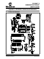
13
8
INVALID 10
FORCEON 12
FORCEOFF 16
14 GND
V- 7
1 EN
9
2
4
5
6
C1+
C1C2+
C211
PICDEM Z MOTHERBOARD
VCC 15
V+ 3
A.1
2004 Microchip Technology Inc.
DS51524A-page 25
PICDEM™ Z Demonstration Kit User’s Guide
A.2
PICDEM Z MOTHERBOARD TOP ASSEMBLY
DS51524A-page 26
2004 Microchip Technology Inc.
PICDEM Z Motherboard Schematics
A.3
PICDEM Z MOTHERBOARD LAYER 1
2004 Microchip Technology Inc.
DS51524A-page 27
PICDEM™ Z Demonstration Kit User’s Guide
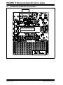
A.4
PICDEM Z MOTHERBOARD LAYER 2
DS51524A-page 28
2004 Microchip Technology Inc.
PICDEM Z Motherboard Schematics
TABLE A-1:
PICDEM Z MOTHERBOARD BILL OF MATERIALS (BOM)
Reference
Description
Vendor
Vendor P/N
D3
Diode Schottky 20V 1A SMD MELF
Diodes Inc.
1N5817M-13
BT1
Conn Batt Male 9V Horz Snap-on
Keystone Electronics
593
BT1
Conn Batt Fem 9V Horz Snap-on
Keystone Electronics
594
Conn PC Vert 9V Snap-on
Keystone Electronics
968
C3, C4
22PF 100V 5% Monolith Cerm Cap
Panasonic - ECG
ECU-S2A220JCA
C1, C2, C5, C7,
C9, C10, C11,
C12, C13, C14
Cap .1UF 16V Ceramic X7R 0805
Panasonic - ECG
ECJ-2VB1C104K
C6
Capacitor Tant 2.2UF 25V 10% SMD
Kemet
T491B225K025AS
C8
Capacitor Tant 3.3UF 16V 10% SMD
Kemet
T491B335K016AS
Y1
Crystal 4.000 MHZ 20PF HC-49/US
ECS Inc.
ECS-40-20-4
P1
DB9 F
J1
Conn Powerjack Mini .1" R/A PCMT
Switchcraft Inc.
RAPC712
2 x 6 .100" Socket/Terminal
Samtec
LST-106-07-F-D
D1, D2
LED Thin 565NM Grn Diff 0805 SMD
Lumex Opto
SML-LXT0805GW-TR
U2
IC Reg LDO Micropower SOT23-5
National Semiconductor LP2981AIM5-3.3
J3
J2
JP2, JP3, JP4
U5
Maxim
MAX3221CAE
Mill-Max
110-99-328-41-001
U4
40-pin Socket (needs to have no internal ribs) Mill-Max
110-99-640-41-001
U4
PICmicro®
Microchip
PIC18LF4620-I/P
R3
No Load
R5, R6
Res 330 OHM 1/8W 5% 0805 SMD
Yageo America
9C08052A3300JLHFT
R2, R7, R8
Res 470 OHM 1/8W 5% 0805 SMD
Yageo America
9C08052A4700JLHFT
R1
Res 4.7K OHM 1/8W 5% 0805 SMD
Yageo America
9C08052A4701JLHFT
R4
Res 1.0M OHM 1/8W 5% 0805 SMD
Yageo America
9C08052A1004JLHFT
J5
Conn Mod Jack 6-6 R/A PCB 50AU
AMP/Tyco
520470-3
S1, S2, S3
Switch Tact 6MM SMD MOM 230GF
Omron Electronics
B3S-1002
S7
Switch Slide SPDT PC MNT L=2MM
E-Switch, Inc.
EG1271
U3
IC Sensor Thermal SPI 3.3V SOT235
Microchip
TC77-3.3MCTTR
Test Point PC Multi Purpose Blk
Keystone Electronics
5011
Test Point PC Multi Purpose Red
Keystone Electronics
5010
U1
28-pin Socket
2004 Microchip Technology Inc.
MCU
DS51524A-page 29
PICDEM™ Z Demonstration Kit User’s Guide
NOTES:
DS51524A-page 30
2004 Microchip Technology Inc.
PICDEM™ Z
DEMONSTRATION KIT
USER’S GUIDE
Appendix B. PICDEM Z 2.4 GHz RF Card
B.1
INTRODUCTION
This appendix presents an overview of the features and requirements of the PICDEM Z
2.4 GHz RF card. Topics covered in this appendix include:
•
•
•
•
•
•
•
•
•
•
•
•
•
B.2
What is the PICDEM Z 2.4 GHz RF Card?
PICDEM Z 2.4 GHz RF Card Kit Components
Overview of the PICDEM Z 2.4 GHz RF Card
The PICDEM Z 2.4 GHz RF Card Features
The PICDEM Z Software
Getting Started with the PICDEM Z 2.4 GHz RF Card
PICDEM Z 2.4 GHz RF Card Schematics
PICDEM Z 2.4 GHz RF Card Top Assembly
PICDEM Z 2.4 GHz RF Card PCB Layer 1
PICDEM Z 2.4 GHz RF Card PCB Layer 2
PICDEM Z 2.4 GHz RF Card PCB Layer 3
PICDEM Z 2.4 GHz RF Card PCB Layer 4
PICDEM Z 2.4 GHz RF Card Bill of Materials (BOM)
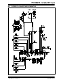
WHAT IS THE PICDEM Z 2.4 GHz RF CARD?
The PICDEM Z 2.4 GHz RF card is designed to plug into a PICDEM Z motherboard.
This board uses the CC2420 RF 2.4 GHz transceiver manufactured by Chipcon. The
CC2420 is an IEEE 802.15.4 compatible RF transceiver for the 2.4 GHz band. Please
refer to www.chipcon.com for more information on the CC2420 RF transceiver.
The PICDEM Z 2.4 GHz RF card uses a PCB trace antenna. If required, the card may
be easily modified to use a standard monopole antenna. The RF schematic and PCB
design are a straight adoption of the CC2420 reference design published by Chipcon.
B.3
PICDEM Z 2.4 GHz RF CARD KIT COMPONENTS
The PICDEM Z 2.4 GHz RF card is designed to be part of the PICDEM Z
Demonstration Kit.
Your PICDEM Z 2.4 GHz RF Card Kit contains the following items:
1. One PICDEM Z 2.4 GHz RF card
2. A warranty registration card
You may download the complete schematic and PCB design files from the Microchip
web site.
2004 Microchip Technology Inc.
DS51524A-page 31
PICDEM™ Z Demonstration Kit User’s Guide
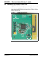
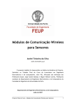
B.4
OVERVIEW OF THE PICDEM Z 2.4 GHz RF CARD
The PICDEM Z 2.4 GHz RF card is designed to demonstrate the Microchip solution for
the ZigBee protocol for the 2.4 GHz frequency band. All design files related to the RF
card are available from the Microchip web site. You may use this board directly in your
design or plug it into a PICDEM Z motherboard to complete the ZigBee node. The
current version of the Microchip Stack for the ZigBee Protocol provides the necessary
software to support this card.
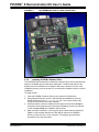
FIGURE B-1:
DS51524A-page 32
PICDEM Z 2.4 GHz RF CARD
2004 Microchip Technology Inc.
PICDEM Z 2.4 GHz RF Card
B.5
THE PICDEM Z 2.4 GHz RF CARD FEATURES
The PICDEM Z 2.4 GHz RF card is designed to use the CC2420 RF transceiver. The
CC2420 is an IEEE 802.15.4 compliant RF transceiver in the 2.4 GHz frequency band.
The card provides a 2-row header to connect to a PICDEM Z motherboard.
The current version of the PICDEM Z 2.4 GHz RF card with on-board PCB trace
antenna was found to provide a line sight radio range of about 200 ft. Exact range
depends on many factors, including but not limited to obstacles, PCB and antenna
design. Microchip has not characterized the RF performance of the Chipcon CC2420
transceiver. For more information about RF characteristics, please refer to Chipcon
web site.
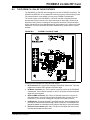
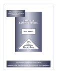
FIGURE B-2:
PICDEM Z 2.4 GHz RF CARD
1
2
4
3
Features on the PICDEM Z 2.4 GHz RF card include:
1. RF Transceiver (U1): 48-pin QLP packaged CC2420 RF transceiver. This chip
implements complete PHY and part of the MAC layer.
2. RF Board Connector (J2): This connector is used to connect to the PICDEM Z
motherboard. This connector includes +3.3V DC, an SPI bus, and a few discrete
digital I/O control signals.
3. Optional SMA Connector (P5): This is an optional connector to use with an
external antenna. You must remove C63 and install C62 to connect P5 to the
transceiver. This connector is designed to accept a mini-SMA connector.
4. PCB Antenna: This is the inverted F-type PCB antenna, which is adopted from
the Chipcon CC2420 DBK board design. Refer to Chipcon’s CC2420DBK User
Manual (available for download from the Chipcon web site) for more information.
5. Revision Level Indicator (back side): The text on the solder side of the board
indicates the hardware revision level.
2004 Microchip Technology Inc.
DS51524A-page 33
PICDEM™ Z Demonstration Kit User’s Guide
B.6
THE PICDEM Z SOFTWARE
You may download the latest version of the PICDEM Z software from the Microchip web
site.
B.7
GETTING STARTED WITH THE PICDEM Z 2.4 GHZ RF CARD
B.7.1
Introduction
This section covers the following topics:
• Motherboard Requirements
• Using the PICDEM Z 2.4 GHz RF Card for the First Time
B.7.2
Motherboard Requirements
The PICDEM Z 2.4 GHz RF card is designed for use with a PICDEM Z motherboard or
similar board. If you are planning to use the RF card with your custom board, use the
PICDEM Z motherboard schematic as a reference (see Section A.1 “PICDEM Z
Motherboard”).
B.7.3
Using the PICDEM Z 2.4 GHz RF Card for the First Time
The PICDEM Z 2.4 GHz RF card must be properly plugged into the PICDEM Z
motherboard to complete the setup. Refer to Figure 2-1 for an example.
Perform the following steps to prepare each node:
1. Remove from box and unwrap each board and place on a non-conductive
surface.
2. Carefully plug the PICDEM Z 2.4 GHz RF card into the J2 connector on the main
board. Note that the connectors on the main board and RF card are polarized
and will not allow incorrect insertion.
3. Power the PICDEM Z motherboard. Observe that LEDs D1 and D2 have flashed.
This confirms that the boards are working properly.
Note:
Before transmitting an RF signal, check with your local telecommunication
authorities to ensure that no restriction on the use of the 2400-2483.5 MHz
ISM band is in effect.
The CC2420 operates in the 2.4 GHz frequency band; however, be advised
that even though this band is commonly thought of as a world-wide band,
some countries do not allow unlicensed operation in this band.
DS51524A-page 34
2004 Microchip Technology Inc.
PICDEM Z 2.4 GHz RF Card
B.8
PICDEM Z 2.4 GHz RF CARD SCHEMATICS
2004 Microchip Technology Inc.
DS51524A-page 35
PICDEM™ Z Demonstration Kit User’s Guide
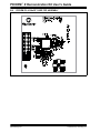
B.9
PICDEM Z 2.4 GHz RF CARD TOP ASSEMBLY
DS51524A-page 36
2004 Microchip Technology Inc.
PICDEM Z 2.4 GHz RF Card
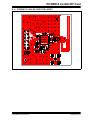
B.10 PICDEM Z 2.4 GHz RF CARD PCB LAYER 1
2004 Microchip Technology Inc.
DS51524A-page 37
PICDEM™ Z Demonstration Kit User’s Guide
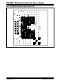
B.11 PICDEM Z 2.4 GHz RF CARD PCB LAYER 2
DS51524A-page 38
2004 Microchip Technology Inc.
PICDEM Z 2.4 GHz RF Card
B.12 PICDEM Z 2.4 GHz RF CARD PCB LAYER 3
2004 Microchip Technology Inc.
DS51524A-page 39
PICDEM™ Z Demonstration Kit User’s Guide
B.13 PICDEM Z 2.4 GHz RF CARD PCB LAYER 4
DS51524A-page 40
2004 Microchip Technology Inc.
PICDEM Z 2.4 GHz RF Card
TABLE B-1:
PICDEM Z 2.4 GHz RF CARD BILL OF MATERIALS (BOM)
Reference
Description
Vendor
Vendor P/N
C1
Capacitor TANT 2.2UF 25V 10% SMD
Kemet
T491B225K025AS
C61, C81
CAP Ceramic .5PF 50V NP0 0402
Yageo America
0402CG508C9B200
C63
CAP Ceramic 5.6PF 50V NP0 0402
BC Components
0402N5R6D500NT
CAP Ceramic 22PF 50V NP0 0402
C62
C381, C391
BC Components
0402N220J500NT
C171, C371, C441, C481 CAP 68PF 50V Ceramic 0402 SMD
Panasonic - ECG
ECJ-0EC1H680J
C101
CAP 10000PF 16V Ceramic X7R 0402
Kemet
C0402C103K4RACTU
C11, C71, C251, C261,
C351
CAP .10UF 10V Ceramic X5R 0402
Kemet
C0402C104K8PACTU
C421, C431
CAP 10UF 6.3V Ceramic X5R 0805
Panasonic - ECG
ECJ-2FB0J106M
U1
CC2420 Single-chip transceiver
Chipcon
CC2420-STB1 QLP48
L62
Inductor 5.6NH +/-0.2NH 0402
Susumu Co Ltd
HPL1005-5N6
L61, L81
Inductor 7.5NH 570MA 0402
Murata Electronics
LQW15AN7N5J00D
R421
RES 2.00 OHM 1/8W 1% 0805 SMD
Yageo America
9C08052A2R00FGHFT
R451
RES 43.0K OHM 1/16W 1% 0402 SMD Yageo America
9C04021A4302FLHF3
Y1
Crystal (second vendor)
Crystek
CSX3-AA-1816.000
Y1
Crystal
TOYOCOM
TSX-10A 16M 16pf
J2
.100" Socket/Terminal
Samtec
LST-106-07-F-D
P5
Conn Recept Straight PCB .110" G
Johnson Components 142-0701-231
2004 Microchip Technology Inc.
DS51524A-page 41
Worldwide Sales and Service
AMERICAS
ASIA/PACIFIC
ASIA/PACIFIC
EUROPE
Corporate Office
2355 West Chandler Blvd.
Chandler, AZ 85224-6199
Tel: 480-792-7200
Fax: 480-792-7277
Technical Support:
http://support.microchip.com
Web Address:
www.microchip.com
Australia - Sydney
Tel: 61-2-9868-6733
Fax: 61-2-9868-6755
India - Bangalore
Tel: 91-80-2229-0061
Fax: 91-80-2229-0062
China - Beijing
Tel: 86-10-8528-2100
Fax: 86-10-8528-2104
India - New Delhi
Tel: 91-11-5160-8631
Fax: 91-11-5160-8632
Austria - Weis
Tel: 43-7242-2244-399
Fax: 43-7242-2244-393
Denmark - Ballerup
Tel: 45-4450-2828
Fax: 45-4485-2829
China - Chengdu
Tel: 86-28-8676-6200
Fax: 86-28-8676-6599
Japan - Kanagawa
Tel: 81-45-471- 6166
Fax: 81-45-471-6122
France - Massy
Tel: 33-1-69-53-63-20
Fax: 33-1-69-30-90-79
China - Fuzhou
Tel: 86-591-8750-3506
Fax: 86-591-8750-3521
Korea - Seoul
Tel: 82-2-554-7200
Fax: 82-2-558-5932 or
82-2-558-5934
Germany - Ismaning
Tel: 49-89-627-144-0
Fax: 49-89-627-144-44
Atlanta
Alpharetta, GA
Tel: 770-640-0034
Fax: 770-640-0307
Boston
Westford, MA
Tel: 978-692-3848
Fax: 978-692-3821
Chicago
Itasca, IL
Tel: 630-285-0071
Fax: 630-285-0075
Dallas
Addison, TX
Tel: 972-818-7423
Fax: 972-818-2924
Detroit
Farmington Hills, MI
Tel: 248-538-2250
Fax: 248-538-2260
Kokomo
Kokomo, IN
Tel: 765-864-8360
Fax: 765-864-8387
China - Hong Kong SAR
Tel: 852-2401-1200
Fax: 852-2401-3431
China - Shanghai
Tel: 86-21-5407-5533
Fax: 86-21-5407-5066
China - Shenyang
Tel: 86-24-2334-2829
Fax: 86-24-2334-2393
China - Shenzhen
Tel: 86-755-8203-2660
Fax: 86-755-8203-1760
China - Shunde
Tel: 86-757-2839-5507
Fax: 86-757-2839-5571
Singapore
Tel: 65-6334-8870
Fax: 65-6334-8850
Taiwan - Kaohsiung
Tel: 886-7-536-4818
Fax: 886-7-536-4803
Taiwan - Taipei
Tel: 886-2-2500-6610
Fax: 886-2-2508-0102
Italy - Milan
Tel: 39-0331-742611
Fax: 39-0331-466781
Netherlands - Drunen
Tel: 31-416-690399
Fax: 31-416-690340
England - Berkshire
Tel: 44-118-921-5869
Fax: 44-118-921-5820
Taiwan - Hsinchu
Tel: 886-3-572-9526
Fax: 886-3-572-6459
China - Qingdao
Tel: 86-532-502-7355
Fax: 86-532-502-7205
Los Angeles
Mission Viejo, CA
Tel: 949-462-9523
Fax: 949-462-9608
San Jose
Mountain View, CA
Tel: 650-215-1444
Fax: 650-961-0286
Toronto
Mississauga, Ontario,
Canada
Tel: 905-673-0699
Fax: 905-673-6509
10/20/04
DS51524A-page 42
2004 Microchip Technology Inc.