1
Brick-2 Videowall Processor
Advanced User Guide
Media
Technologies
CONTENTS
Page
1
BRICK-2 VIDEOWALL PROCESSOR ARCHITECTURE ..................................................................... 3
2
RS-232 LINK PROTOCOL ................................................................................................................... 4
PHYSICAL CONNECTION .......................................................................................................................... 4
SERIAL COMMUNICATIONS FRAME STRUCTURE .................................................................................. 4
3
CONNECTING THE PROCESSOR ...................................................................................................... 7
4
EFFECTS COMMANDS ....................................................................................................................... 9
VIDEO INPUT COMMANDS........................................................................................................................12
VIDEO OUTPUT COMMANDS....................................................................................................................15
EFFECTS COMMANDS..............................................................................................................................17
TIMEBASE CORRECTOR FUNCTIONS ( TBC ) .........................................................................................22
COLOUR CYCLE ........................................................................................................................................25
SEQUENCE EXECUTION FUNCTIONS .....................................................................................................26
GRAPHICS FUNCTIONS............................................................................................................................27
5
CONTROL SOFTWARE INTRODUCTION..........................................................................................32
COMPUTER REQUIREMENTS ..................................................................................................................32
INSTALLING THE SOFTWARE..................................................................................................................32
RUNNING THE PROGRAM........................................................................................................................33
SEQUENCE FILE EXECUTION ..................................................................................................................33
6
CONTROL SOFTWARE USER GUIDE ...............................................................................................34
QUIT...........................................................................................................................................................34
HELP ..........................................................................................................................................................34
INITIAL MENU ............................................................................................................................................34
VIDEO MENU .............................................................................................................................................34
SPLIT MENU ..............................................................................................................................................36
PROJECT MENU........................................................................................................................................36
SEQUENCE MENU.....................................................................................................................................37
CONFIGURE MENU ...................................................................................................................................41
ALIGNMENT MENU....................................................................................................................................43
7
CREATING SEQUENCES ...................................................................................................................44
SEQUENCE FILE FORMAT ........................................................................................................................44
COMMAND DEFINITIONS..........................................................................................................................44
8
DOS COMMAND LINE EXECUTION...................................................................................................52
COMMAND LINE INVOCATION .................................................................................................................53
9
FLASH MEMORY UTILITY .................................................................................................................55
FLASH MEMORY COMMANDS ..................................................................................................................55
10
LOW LEVEL MONITOR...................................................................................................................58
BOOT PROCESS .......................................................................................................................................58
FLASH FILE SYSTEM RECOVERY ............................................................................................................58
11
SPECIFICATION..............................................................................................................................60
Brick-2 Videowall Processor Advanced User Guide
Issue 7
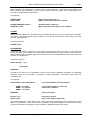
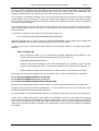
1 BRICK-2 VIDEOWALL PROCESSOR ARCHITECTURE
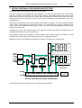
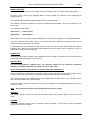
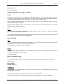
The Brick-2 videowall processor architecture is shown below.
The Brick consists of two independent video digitisers. The second video digitiser has a video buffer
memory to enable synchronisation with the first video digitiser. Video fields are streamed into the video
frame memory which can store up to four video fields. The output of the frame buffer is fed to the video
output processors which magnify the portion of the image to be displayed on the particular monitor in the
videowall array.
Various pixel switching and pixel intensity effects are provided in hardware. The video output processors
include colour wash registers to enable each monitor in the videowall array to display a different colour
wash. These colour washes block the display of video and can be dynamically switched to enable wipes
between wash and video.
In addition to a wash, each output processor can select each video input channel to enable both to be
displayed simultaneously on the videowall array.
The powerful on-board microcomputer can write directly into the video memory to enable on screen
messages and simple graphics to be displayed without any additional hardware.
Mux
S-Video
Decoder
B
Frame
Memory
Timebase
Correction
C-Video 1
C-Video 2
X-Y Window
BUS-A
Filter/Buffer
Encoder
Pixel Processing
S-Video
C-Video
Optional Expansion to 25 Outputs
Filter/Buffer
Decoder
A
BUS-B
Encoder
S-Video
BUS-A
Pixel Processing
C-Video 1
C-Video 2
Bus Multiplexor
Expansion Port
Bitmaps can also be downloaded and displayed to enable for example your company logo.
S-Video
C-Video
BUS-B
Zoom Tables
16
Video Outputs
Host RS232
CPU, Flash Memory and Timing Logic
JTAG FPGA
Programming
Interface
Loop RS232
Brick-2 Videowall Processor Architecture
Communications with the processor are via a simple RS-232 interface.
Copyright Media Technologies, 1999 – 2006
Page 3 of 61
Brick-2 Videowall Processor Advanced User Guide
Issue 7
2 RS-232 LINK PROTOCOL
Communications with the processor are carried out via the RS-232 interface. The protocol is designed to
be robust and reliable and is based on the well known HDLC technique. It is byte-transparent, that is, any
8-bit value can be sent to the processor using the framing characters. A simple single-character
command mode is also supported to enable pre-loaded effects sequences to be triggered using single
keyboard characters in conjunction with a standard terminal emulator such as that provided with
WindowsTM or Macintosh.
PHYSICAL CONNECTION
The wiring of the cable for connection between a PC/AT 9-pin 'D' serial connector and the Processor is
as follows:
Computer
Pin 2
Pin 3
Pin 5
Processor
ó
ó
ó
Pin 2
Pin 3
Pin 5
The protocol is intended to be used with RS-232 serial communications devices. The default
communications parameters are as follows:
Speed
19200 baud
Data bits
8
Stop Bits
1
Parity
None
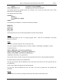
SERIAL COMMUNICATIONS FRAME STRUCTURE
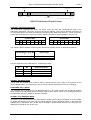
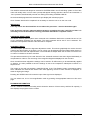
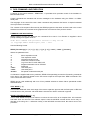
The Serial RS-232 communications frame structure is common to both directions of transmission.
Messages are delimited by start and end of message flags. A single byte checksum is appended to the
end of the message. The message is preceded by two bytes of additional data, a control and address
byte as shown below:
<SOM> , <Control>, <Address>, [<Message data...>], <Checksum>, <EOM>
Frames are delimited by a start and end of message character. The body of the frame comprises the
control and address bytes the message (which is optional), and a checksum.
Frames not containing any message bytes are referred to as 'null' frames.
The start and end of messages are special character values that must not occur in the data bytes
between them to ensure correct message framing. To achieve this a third value, the byte stuff character,
(BSF) is used. This is also a unique character value that also must not appear as a data byte.
The byte values of these three special characters are:
SOM
EOM
BSF
= 0x7E
= 0x7D
= 0x7C
Byte transparency is achieved by replacing any of the three special characters that occur as data bytes
with a two byte sequence headed by the BSF character. The second character is the character X-ORed
with the 'smudge' character, 0x20, which prevents recognition by the receiver as a special byte. e.g. a
data byte 0x7E is replaced with the byte pair: 0x7C,0x5E.
Copyright Media Technologies, 1999 – 2006
Page 4 of 61
Brick-2 Videowall Processor Advanced User Guide
CONTROL
START = 7E
Issue 7
CHECKSUM
ADDRESS
END = 7D
MESSAGE DATA
BYTE STUFF CHARACTER = 7C
RS-232 Link Protocol Frame Format
CONTROL AND ADDRESS BYTES
The control byte comprises two fields. The upper 4 bits are mode bits controlling the using of the
addressing information. The lower 4 bits are the Device Address. In the receive direction (Processor to
PC) the mode bits are not used. (Unused bits are marked in the table below with an 'x' ) As a convention,
unused bits should be set to zero, but receiving software should not reject messages if they are not.
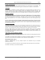
Transmit Bits
7
M1
6
M0
5
x
4
x
3
A3
Receive Bits
2
A2
1
A1
0
A0
7
x
6
x
5
x
4
x
3
A3
2
A2
1
A1
0
A0
The following Device Address code has been allocated to the Brick series of videowall processors:
Device Address [ A3 to A0
]
Device Type
RESERVED
Brick Processor
0-6
7
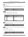
The two mode bits M1 and M0 allow for 4 addressing modes:
M1
M0
Addressing Mode
0
0
1
1
0
1
0
1
Normal Address
Response (Poll)
Global of type (A3 to A0)
Global all units.
NORMAL ADDRESS MODE
In this mode, the address byte is used to select a specific device (one of 256), of the type set by the
device address field in the control byte. Only one unique device will therefore act on the message.
RESPONSE (POLL) MODE
The message will be received by the addressed device in the same manner as the Normal Address
mode, however the addressed device will respond with a return frame. If there is no message pending in
the addressed device the response will be a null frame.
GLOBAL TYPE ADDRESS MODE
All devices of the type defined in the control bytes unit field will act upon this message. It is not possible
to globally poll devices since more than one would respond and the messages collide. In this mode the
address byte is redundant, but it is still sent to maintain a simple frame structure. By convention the
address byte should be zero in this case.
Copyright Media Technologies, 1999 – 2006
Page 5 of 61
Brick-2 Videowall Processor Advanced User Guide
Issue 7
GLOBAL ADDRESS MODE
This is similar to the previous case except that all devices of any type will act on the message. The
usefulness of this mode is really restricted to generic commands such as 'RESET' and 'BAUDRATE'
CHECKSUM
The checksum is calculated by summing modulo-256, all of the bytes between the start and end of
message characters, prior to the byte stuffing process, and subtracting this figure from zero. The
receiver checks the received data by summing all the bytes following the start of message (after
expanding the 'stuffed' bytes). When the end of message character is received the sum should be zero.
MESSAGE CONTENTS
The length of the message is not limited by the protocol. As described above, it can be of zero length for
use in polling and null responses, where there is otherwise no data to transfer. The message format is
the same for both directions of transmission, comprising a function code in the range 0 to 255 followed
by an optional parameter list. The convention for parameters greater then 255 is least significant byte
first.
Function codes are device specific and detailed in separate manuals for each device. The function codes
from 0 to 15 are reserved for generic operations, such as returning software version numbers, which all
devices support. In addition there are generic function codes to support extended addressing techniques
for selecting multiple devices.
PROTOCOL VIOLATIONS
Any protocol violations should cause the current message to be abandoned. The receiver will revert to a
mode waiting for the start of message character. If the violation was an out of sequence start of message
character, a new message will be assumed. Message frames with checksum errors are ignored.
Although the BSF character would normally only precede a 'smudged' version of one of the 3 special
byte codes, (SOM, EOM, BSF) the presence of any other character is not considered a violation. The
'un-smudging' process should be applied regardless of the 'smudged' character code provided it is not
either SOM, EOM or BSF.
USING SEND TO DECODE MESSAGE FRAMES
Software shipped with Media Technologies videowall processors includes a message programme called
SEND.EXE.
Type SEND at the DOS prompt to display the command line switches available. Use the following
command to see what bytes are transmitted by a given videowall command sequence:
SEND EXAMPLE.SEQ -COM1: -L
Instead of "EXAMPLE.SEQ" use any example sequence file assembled using the videowall
programming software.
This creates a text file called TX.LOG which contains information about the bytes sent to the serial port.
Use COM2: if necessary for your software installation.
Copyright Media Technologies, 1999 – 2006
Page 6 of 61
Brick-2 Videowall Processor Advanced User Guide
Issue 7
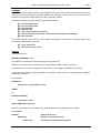
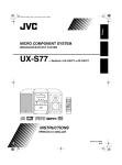
3 CONNECTING THE PROCESSOR
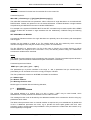
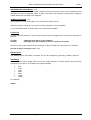
The physical layout of the Brick-2 videowall processor is shown below.
Select Effect
Video Input-1
Video
Outputs at
Rear
Video Input-2
Earth Testing
Point
Host RS-232
(Computer)
Loop RS-232
(Slave Processor)
Set Default
Magnification
(Split)
Figure-2 : Positions of Processor Switches and Connectors
The Brick-2 videowall processor is controlled via the Host RS-232 connector. The connector is a
standard 9-pin 'D' connector with a one-one pin mapping to the standard IBM PC COM port connectors only 3 wires are required for correct operation. The Loop RS-232 connector is only required when other
RS-232 devices, typically stacked Brick processors need to be controlled from a single PC COM port.
The Loop RS-232 connector is a standard 9-pin 'D' connector with a crossover pin mapping relative to
Host RS-232 connector, to enable slave units to be daisy chained (Loop RS-232 ó Host RS-232, etc.)
using an identical cable to that used for the host interface (supplied).
Pin assignments of all the connectors are given below.
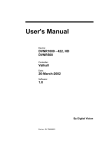
S-Video Input Connector [ 4-pin Mini-DIN ]
Pin
1
2
3
4
Signal
'Y' Screen / GND
'C' Screen / GND
'Y' video signal
'C' video signal
Type
Input
Input
4
3
1
2
Front View
S-Video Output Connector [ 4-pin Mini-DIN ]
Pin
1
2
3
4
Signal
'Y' Screen / GND
'C' Screen / GND
'Y' video signal
'C' video signal
Type
Output
Output
4
2
3
1
Front View
Copyright Media Technologies, 1999 – 2006
Page 7 of 61
Brick-2 Videowall Processor Advanced User Guide
Issue 7
Host RS-232 Connector [ 9-pin Male 'D' ]
Pin
1
2
3
4
5
6-9
Signal
Type
Not used
Output
Input
Host-TX
Host-RX
Not used
-
GND
Not used
Loop RS-232 Connector [ 9-pin Male 'D' ]
Pin
1
2
3
4
5
6-9
Signal
Type
Not used
Input
Output
Host-RX
Host-TX
Not used
-
GND
Not used
Copyright Media Technologies, 1999 – 2006
Page 8 of 61
Brick-2 Videowall Processor Advanced User Guide
Issue 7
4 EFFECTS COMMANDS
This section is intended for advanced users who wish to create their own complex videowall effects
sequences. Simple configurations of magnifications and colour washes can be achieved directly from the
control software supplied without the need to understand these commands.
Examples are provided on the distribution disk which should be consulted to gain a further insight into
the application of these commands.
Function codes are used in messages with either the BRICK2.EXE or SEND.EXE programs. The
functions may have a number of parameters and are preceded by the address of the device to which
they are directed.
SEND 7 0 FN_CODE p1 .. pn
SEND
7
0
FN_CODE
p1 .. pn
: Builds and sends a message to the selected device.
: The device type for the BRICK processor
: The sub-address of the device type.
: Command code, 0 to 255 binary
: Optional parameters
For example, to set the global split to 4x4…
SEND 7 0 40 4
Where 40 is the function code to set the split factor.
Some functions require 16 bit parameters. These can be created by preceding them with the '&'
character. For example, to position the graphics cursor:..
SEND 7 0 85 &100 &100
String parameters are required by some functions. These are terminated with a zero character which
must be done explicitly using send. For example:
SEND device address FN_CODE "string" 0
Commands and parameter names in CAPITALS are the function names used in sequence programme
scripts, they are defined in the system file "STD.INC".
It is possible (but not recommended) to edit "STD.INC" to customise the names for function commands,
for example to substitute words in another language.
For example, the sample command to set the split above has been defined as follows to make it easier
to use.
SETSPLIT 4
Commands have two attributes, immediate and sequence. Commands with the immediate attribute are
executed when they are received. Commands that do not have this attribute are queued and execute
when the current background task completes. If there is no background task they also execute
immediately. This allows commands such as WIPE to be sent one after the other, without the next
command being executed before the current command completes.
It is possible to change the immediate behaviour using the IMMEDIATE command. A command sent
after the IMMEDIATE command will act immediately regardless of its immediate attribute.
Commands with the sequence attribute will execute in downloaded sequence files. Commands without
this attribute are commands that would normally be used with an external control program and could
have a detrimental effect if executed locally within a downloaded sequence, e.g. RESET.
Copyright Media Technologies, 1999 – 2006
Page 9 of 61
Brick-2 Videowall Processor Advanced User Guide
Issue 7
The following function codes are available to the user. Other codes not specified here are either reserved
or not intended to be directly accessible by the user.
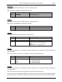
RESET
Resets the addressed device.
All internal parameters are set to their power on reset state. The device configuration is derived from a
combination of front panel switches and configurations stored in on-board Flash memory.
Parameters
Byte
Parameter
Comment
Code
RESET
Function code = 00
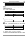
BAUDRATE
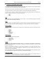
Sets the baud rate for the addressed device serial communications.
On power-up or reset the processor baud rate is always set to 19200.
This command should be sent to all devices in the system to set a new communications rate.
Byte
Parameter
Comment
Code
BAUDRATE
Function code = 01
1
0
1
2
3
4
5
6
7
1200
2400
4800
9600
19200
38400
300
19200 Default
SETDEF
Resets the videowall digitiser, encoder and monitor alignment configuration from the saved values. This
occurs naturally following a reset or power-up.
Byte
Parameter
Comment
Code
SETDEF
Function code = 02
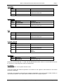
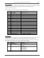
CONFIG
Causes the addressed device to place data in the output buffer containing the state of the card
configuration switches.
The data is read using the 'POLL' command.
There are no parameters associated with this command.
Byte
Parameter
Comment
Code
GETCFG
Function code = 03
Returned Data…
Copyright Media Technologies, 1999 – 2006
Page 10 of 61
Brick-2 Videowall Processor Advanced User Guide
Byte
Parameter
Comment
Code
GETCFG
Function code = 0 3
1
2
0..15
0..15
Hex switch 1 setting (Split)
Hex switch 2 setting (Effects)
Issue 7
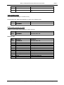
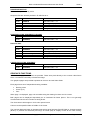
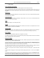
RELEASE
Causes the addressed device to place data in the output buffer containing the firmware version.
The data is read using the 'POLL' command.
There are no parameters associated with this command.
Byte
Parameter
Comment
Code
GETRLS
Function code = 04
Returned Data…
Byte
Parameter
Comment
Code
GETRLS
Function code = 04
1
2
3 .. n
Major
Minor
ASCII Text Message
Version Number MAJOR
Version Number MINOR
Software release name
KILL
Kill any background task currently executing
Byte
Parameter
Comment
Code
KILL
Function code = 05
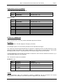
SETID
Set the unit identity. This is only required when multiple Brick units are used, for splits greater than 5x5
for example. If ordered at the same time units will be supplied with the ID already preset.
Byte
Parameter
Comment
Code
SETID
Function code = 06
1
2
3
4
5
New ID
Default split
Hardware mode
X offset
Y offset
Address 0 .. 255
1 .. 8
0
Horizontal location of first monitor
Vertical location of first monitor
The default split is applied on power up if the split front panel ‘Split’ switch is set to zero.
The hardware mode, X and Y offset values depend on the global split required and number of Brick units
used. A standard unit i.e. for splits from 1x1 to 5x5 should have these values set to 0.
For non-standard configurations any non-zero values required for the hardware mode, X or Y offsets will
be noted in the hardware specific documentation supplied.
Copyright Media Technologies, 1999 – 2006
Page 11 of 61
Brick-2 Videowall Processor Advanced User Guide
Issue 7
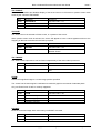
GO
Execute a held command. Used in multi-device applications. A hold command may be broadcast to all
devices followed by a command to each device, which is held. Following a broadcast GO command all
devices will execute the held command synchronously.
Byte
Parameter
Comment
Code
GO
Function code = 07
HOLD
Hold a command, pending a later GO command
Byte
Parameter
Comment
Code
HOLD
Function code = 08
IMMEDIATE
Force the next command to be executed immediately.
Byte
Parameter
Comment
Code
IMMEDIATE
Function code = 09
VIDEO INPUT COMMANDS
These commands are used to change the video input configurations.
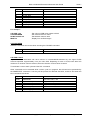
SELECT VIDEO INPUT
Each input can select either a Composite Video Input (via the BNC connectors) or S-Video via the SVideo connectors.
Byte
Parameter
Comment
Code
VIDEOINPUT
Function code = 16
1
0
1
0
1
2
Video Input Channel 1
Video Input Channel 2
Composite Video Input 1
Composite Video Input 2
S-Video Input
Byte
Parameter
Comment
Code
BRIGHTNESS
Function code = 17
1
0
1
0 .. 255
Video Input Channel 1
Video Input Channel 2
Brightness
2
BRIGHTNESS
2
Copyright Media Technologies, 1999 – 2006
Page 12 of 61
Brick-2 Videowall Processor Advanced User Guide
Issue 7
CONTRAST
Byte
Parameter
Comment
Code
CONTRAST
Function code = 18
1
0
1
0 .. 255
Video Input Channel 1
Video Input Channel 2
Contrast
Byte
Parameter
Comment
Code
SATURATION
Function code = 19
1
2
0
1
0 .. 255
Video Input Channel 1
Video Input Channel 2
Saturation
Byte
Parameter
Comment
Code
HUE
Function code = 20
1
0
1
0 .. 255
Video Input Channel 1
Video Input Channel 2
Hue
2
SATURATION
HUE
2
COLOUR SYSTEM
Byte
Parameter
Comment
Code
VIDEOSYSTEM
Function code = 21
1
0
1
0
1
2
Video Input Channel 1
Video Input Channel 2
PAL
NTSC
SECAM
Byte
Parameter
Comment
Code
FIELDRATE
Function code = 22
2
FIELDRATE
Returns the current field rate +/- 1 field. For PAL/SECAM this will be 49,50 or 51 and for NTSC 59,60 or
61. If there is no input signal the value is indeterminate.
AUTOMODE
Sets the automatic colour system selection mode.
If set ON the Brick will detect the presence of an NTSC or PAL signal to Video Channel-1 and set the
processor accordingly.
If set OFF, the processor will operate as configured regardless of the input system usually resulting in
unpredictable operation if the input system is different from the configured system.
Copyright Media Technologies, 1999 – 2006
Page 13 of 61
Brick-2 Videowall Processor Advanced User Guide
Byte
Parameter
Comment
Code
AUTOMODE
Function code = 23
1
0
1
Off
On
Issue 7
VIDEO SOURCE SAVE
Save video source settings in FLASH memory.
Saved settings are applied automatically on power-up or software reset.
Byte
Parameter
Comment
Code
SAVEINPUT
Function code = 24
READ VIDEO SOURCE SETTINGS
Reads the current video source settings for both channels.
Byte
Parameter
Comment
Code
READINPUT
Function code = 25
Byte
Parameter
Comment
Code
READINPUT
Function code = 25
1
2
3
4
5
6
7
8
9
10
11
12
13
Brightness
Contrast
Saturation
Hue
Brightness
Contrast
Saturation
Hue
Colour System
Colour System
Source
Source
Automode
Video Input Channel 1
Video Input Channel 1
Video Input Channel 1
Video Input Channel 1
Video Input Channel 2
Video Input Channel 2
Video Input Channel 2
Video Input Channel 2
Video Input Channel 1
Video Input Channel 2
Video Input Channel 2
Video Input Channel 2
0 = disabled, 1 = enabled.
Returned Data
Copyright Media Technologies, 1999 – 2006
Page 14 of 61
Brick-2 Videowall Processor Advanced User Guide
Issue 7
VIDEO OUTPUT COMMANDS
These commands are used to change the video output configurations.
VIDEO OUTPUT MODE
The video outputs can be configured for RGB, Composite Video, or disabled. All outputs channels will be
set to the same configuration.
Colour Systems supported are PAL, NTSC or SECAM.
Byte
Parameter
Comment
Code
DISPLAYMODE
Function code = 30
1
0
1
2 [ Future ]
Composite
S-Video
Dual Composite [ Not supported currently ]
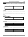
READ MONITOR STATE
Byte
Parameter
Comment
Code
RDMONST
Function code = 31
1
Monitor
0 .. 24
Returned Data = state information on one video output channel (display monitor).
Byte
Parameter
Comment
Code
RDMONST
Function code = 31
1
0
1
2
3
Wash Y
Wash U
Wash V
Wash R
Wash G
Wash B
Video source A - magnified by split
Video source B - not magnified (x1)
Wash
Colour Bars
Colour wash values in YUV format
2
3
4
5
6
7
Colour wash values in RGB format
SAVE VIDEO OUTPUT SETTINGS
Save the current video output settings in a file in FLASH memory.
These settings will automatically be applied on power-up or reset.
Byte
Parameter
Comment
Code
SAVEOUTPUT
Function code = 34
READ VIDEO OUTPUT SETTINGS
This command reads back the current video output settings. The returned parameter corresponds to byte
1 of function 30.
Copyright Media Technologies, 1999 – 2006
Page 15 of 61
Brick-2 Videowall Processor Advanced User Guide
Byte
Parameter
Comment
Code
READOUTPUT
Function code = 35
Byte
Parameter
Comment
Code
READOUTPUT
Function code = 35
1
0
1
2 [ Future ]
0
1
Vertical offset
Horizontal offset
Number of Monitors
0
1
2
Composite
S-Video
Dual Composite [ Future ]
Off
On
Issue 7
Returned data.
2
3
4
5
6
16 or 25
Pixel Filter Off
Pixel Filter On
Pixel Filter intermediate
Note : Pixel filtering is not yet available in current versions of firmware. Contact us for availability.
ADJUST VIDEO OUTPUT HORIZONTAL ALIGNMENT
Move a vertical column of monitor images left or right. The offset is specified in pixels but is actually only
possible in increments of magnified pixels.
Byte
Parameter
Comment
Code
ALIGNH
Function code = 36
1
2
Column
Offset
0 .. 4
Signed byte
ADJUST VIDEO OUTPUT VERTICAL ALIGNMENT
Move a horizontal row of images up or down. The offset is specified in pixels but is actually only possible
in increments of magnified lines.
Byte
Parameter
Comment
Code
ALIGNV
Function code = 37
1
2
Row
Offset
0 .. 4
Signed byte
SAVE VIDEO OUTPUT ALIGNMENT IN FLASH MEMORY
Saves the current alignment settings in a file in FLASH memory in the processor.
These settings will be applied automatically on power-up or reset.
Byte
Parameter
Comment
Code
SAVEALIGN
Function code = 38
Copyright Media Technologies, 1999 – 2006
Page 16 of 61
Brick-2 Videowall Processor Advanced User Guide
Issue 7
READ VIDEO OUTPUT ALIGNMENT
Reads back the current alignment settings.
Byte
Parameter
Comment
Code
READALIGN
Function code = 39
Byte
Parameter
Comment
Code
READALIGN
Function code = 39
1
2
1
2
3
4
5
6
7
8
Row 1
Column 1
Row 2
Column 2
Row 3
Column 3
Row 4
Column 4
Row 5
Column 5
Signed byte
Returned Data.
EFFECTS COMMANDS
These commands are commonly used to assemble sequences of effects.
SET SPLIT
Set the split factor. This will magnify the image by the factor.
For example a split of 2 on a 4x4 array will result in four identical 2x2 images.
The vertical and horizontal shift parameters are optional. If supplied and set to a value other than 0, they
cause the image to be offset by the number divided by 2. In the case of a vertical shift of 1 this moves
the image up half a screen. A horizontal shift of 2 moves the image to the left one monitor.
A typical application of this function is to position a ‘letter box’ source across a subset of monitors, e.g. a
4x4 magnified image on a 4x3 videowall.
The command to achieve this would be…
SETSPLIT 4 1 0
Byte
Parameter
Comment
Code
SETSPLIT
Function code = 40
1
2
Split
0 = No shift
15 = Shift
0 = No shift
15 = Shift
1 to 8
Optional Vertical shift, default 0.
3
Optional Horizontal shift, default 0.
ASPLIT
Set an asymmetric split. This command is similar to SETSPLIT but the horizontal and vertical
magnifications can be different. No monitor shifts are supported by this command.
Copyright Media Technologies, 1999 – 2006
Page 17 of 61
Brick-2 Videowall Processor Advanced User Guide
Issue 7
For example to set a horizontal split of 4 and a vertical split of 1 (vertically squashed image)…
ASPLIT 4 2
Byte
Parameter
Comment
Code
ASPLIT
Function code = 100
1
2
Horizontal Split
Vertical Split
1 to 8
1 to 8
WASHCOLOUR
Set the colour wash for a given monitor or all monitors simultaneously.
The command will have no direct visual effect unless a wash is already selected on a given display
monitor. When a monitor display mode is set to WASH the colour set with this command will be applied.
If a wash is currently displayed the on-screen colour will be updated.
Byte
Parameter
Comment
Code
WASHCOLOUR
Function code = 41
1
2
3
4
Monitor
Red Intensity
Green Intensity
Blue Intensity
0 .. 15 or 255 for all monitors
0 .. 255
0 .. 255
0 .. 255
NORMAL
This command sets the pixel intensity mode to normal and is normally used following a pixel intensity
video effect command such as SOLARISE, NEGATIVE, Etc.
Byte
Parameter
Comment
Code
NORMAL
Function code = 96
1
0
0 = Normal Video
SOLARISE
This command sets the pixel intensity mode to truncate the lower 5 bits to give the video a halo
appearance.
Remove using the NORMAL command (Function 96).
Byte
Parameter
Comment
Code
SOLARISE
Function code = 96
1
1
1 = Solarised Video
Copyright Media Technologies, 1999 – 2006
Page 18 of 61
Brick-2 Videowall Processor Advanced User Guide
Issue 7
NEGATIVE
This command sets the pixel intensity mode to a negative image.
Remove using the NORMAL command (Function 96).
Byte
Parameter
Comment
Code
NEGATIVE
Function code = 96
1
2
2 = Negative Video
DAZZLE
This command sets the pixel intensity mode to a highlighting effect.
Remove using the NORMAL command (Function 96).
Byte
Parameter
Comment
Code
DAZZLE
Function code = 96
1
4
4 = Dazzle Video
DISPLAY
This command sets the display mode for a given monitor.
Byte
Parameter
Comment
Code
DISPLAY
Function code = 42
1
2
Monitor
0
1
2
3
0 .. 24 or 255 for all monitors
Video source A - magnified by split
Video source B - not magnified (x1)
Wash
Colour Bars – for test purposes
FREEZE
This command freezes (or un-freezes) the primary frame store and affects all monitors displaying a
magnified picture.
The frozen image can be either a single field or a full frame (interlaced image).
Byte
Parameter
Comment
Code
FREEZE
Function code = 44
1
OFF
ODD
EVEN
BOTH
0 = Unfreeze - Full Motion Video
1 = Freeze odd field
2 = Freeze even field
3 = Freeze both fields
STROBE
This command freezes (or un-freezes) the primary frame store and affects all monitors displaying a
magnified picture.
The frozen image can be either a single field or a full frame (interlaced image).
The strobe effect is a fundamental attribute of the video image, and does not use a background process
to achieve the effect. Therefore all of the other effects can be used in conjunction with a strobed image.
Copyright Media Technologies, 1999 – 2006
Page 19 of 61
Brick-2 Videowall Processor Advanced User Guide
Issue 7
Byte
Parameter
Comment
Code
STROBE
Function code = 45
1
Speed
0 - 255, Increasing number = Decreasing
Speed. 0 = strobe off
TEXT MODE ( INTERLACE )
Sets the global operation to text mode. This is equivalent to non-interlaced.
Text will flicker if displayed in interlaced mode due to the strong horizontal components in the image.
Byte
Parameter
Comment
Code
TEXTMODE
Function code = 46
1
OFF
ON
0 = Interlaced
1 = Text mode (non-interlaced)
INTERLACE OFFSET
When interlaced mode is selected it is possible to set the number of magnified lines between fields for
each split factor. Under some conditions it is possible to improve the visual impact by adjusting this
offset.
WARNING - if the interlace offset is set to an illegal value for a given split factor, the display will flicker
strongly at the field rate and will not be acceptable.
Byte
Parameter
Comment
Code
IOFFSET
Function code = 48
1
2
Split 1..4
Offset +/- N
Split factor
Signed offset
Copyright Media Technologies, 1999 – 2006
Page 20 of 61
Brick-2 Videowall Processor Advanced User Guide
Issue 7
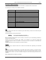
SELECT MONITOR
Using this command it is possible to create an arbitrary set of monitors which will respond to global
commands. This reduces the number of messages necessary to achieve a given effect.
By default all monitors are selected.
It remains possible to directly access a specific monitor by its address.
Byte
Parameter
Comment
Code
SELECTMON
Function code = 47
1
2
3
4
5
6
7
8
9
10
11
12
13
14
15
16
17
18
19
20
21
22
23
24
25
Flag
Flag
Flag
Flag
Flag
Flag
Flag
Flag
Flag
Flag
Flag
Flag
Flag
Flag
Flag
Flag
Flag
Flag
Flag
Flag
Flag
Flag
Flag
Flag
Flag
1 = Selected,
1 = Selected,
1 = Selected,
1 = Selected,
1 = Selected,
1 = Selected,
1 = Selected,
1 = Selected,
1 = Selected,
1 = Selected,
1 = Selected,
1 = Selected,
1 = Selected,
1 = Selected,
1 = Selected,
1 = Selected,
1 = Selected,
1 = Selected,
1 = Selected,
1 = Selected,
1 = Selected,
1 = Selected,
1 = Selected,
1 = Selected,
1 = Selected,
[ Monitor 0 ]
[ Monitor 1 ]
[ Monitor 2 ]
[ Monitor 3 ]
[ Monitor 4 ]
[ Monitor 5 ]
[ Monitor 6 ]
[ Monitor 7 ]
[ Monitor 8 ]
[ Monitor 9 ]
[ Monitor 10 ]
[ Monitor 11 ]
[ Monitor 12 ]
[ Monitor 13 ]
[ Monitor 14 ]
[ Monitor 15 ]
[ Monitor 16 ]
[ Monitor 17 ]
[ Monitor 18 ]
[ Monitor 19 ]
[ Monitor 20 ]
[ Monitor 21 ]
[ Monitor 22 ]
[ Monitor 23 ]
[ Monitor 24 ]
0 = Deselected
0 = Deselected
0 = Deselected
0 = Deselected
0 = Deselected
0 = Deselected
0 = Deselected
0 = Deselected
0 = Deselected
0 = Deselected
0 = Deselected
0 = Deselected
0 = Deselected
0 = Deselected
0 = Deselected
0 = Deselected
0 = Deselected
0 = Deselected
0 = Deselected
0 = Deselected
0 = Deselected
0 = Deselected
0 = Deselected
0 = Deselected
0 = Deselected
TEST PATTERN
This function will draw a test pattern on the display using the graphics facilities. Each monitor has two
diagonal lines drawn from opposite corners and a circle with the channel number in the centre.
The channel numbers are written using the font “TEST.FNT”. If this file is not present in FLASH sector 4,
the test pattern will still be drawn but no channel numbers will be displayed.
Byte
Parameter
Comment
Code
TESTPATTERN
Function code = 51
1
0
1
0
1
2
3
4
5
Use field 0
Use field 1
Use current split
Draw for split = 1
Draw for split = 2
Draw for split = 3
Draw for split = 4
Draw for split = 5
2
Copyright Media Technologies, 1999 – 2006
Page 21 of 61
Brick-2 Videowall Processor Advanced User Guide
Issue 7
WIPE
This command provides wipes between a graphics colour mask (similar effect to a WASH) and video. It
also wipes between the two video sources.
Byte
Parameter
Comment
Code
WIPE
Function code = 52
1
0
1
2
3
4
5
0
1
2
Speed
Right
Left
Down
Up
In (Iris)
Out (Iris)
Wipe to source A
Wipe to source B
Wipe to graphics colour
Range 1 - 255, increasing speed, 0 = Instant
2
3
TIMEBASE CORRECTOR FUNCTIONS ( TBC )
The second video input source is processed internally using time base correction (TBC) to synchronise it
to the main video input source. This allows correct display of two video sources which are not externally
synchronised.
TBC ALTERNATE FIELD
The TBC is selected to store alternate fields or every field.
Use this command to reduce interlace flicker on the second source.
Byte
Parameter
Comment
Code
TBCALT
Function code = 55
1
0
1
OFF
ON
TBC WINDOW POSITION
When TBC MODE (see below) is set to quarter size, this command sets the monitor quadrant in which
the window is displayed.
Byte
Parameter
Comment
Code
TBCWINDOW
Function code = 56
1
0
1
2
3
Top Left
Top Right
Bottom Left
Bottom right
Copyright Media Technologies, 1999 – 2006
Page 22 of 61
Brick-2 Videowall Processor Advanced User Guide
Issue 7
TBC ENABLE
This command enables and disables display of the second source in full screen or quarter screen mode
as set by the command TBC MODE.
Byte
Parameter
Comment
Code
TBCENABLE
Function code = 57
1
0
1
OFF
ON
TBC SIZE
The second source is selected to fill the screen, or a quarter of the screen.
When quarter screen mode is selected, the source will appear to have a coarse appearance due to the
dropping of alternate vertical and horizontal input pixels.
Byte
Parameter
Comment
Code
TBCSIZE
Function code = 58
1
0
1
Full Screen
Quarter Screen
TBC FREEZE
The second video input source can be frozen independently of the main video input source.
Byte
Parameter
Comment
Code
TBCFREEZE
Function code = 59
1
0
1
OFF
ON
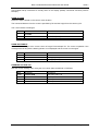
ZOOM
Zooms the magnified image to a centre image position specified.
The screen has the same logical co-ordinates as used with graphics commands of 380x300 pixels.
Only one Zoom factor of 50% is currently supported.
Byte
Parameter
Comment
Code
ZOOM
Function code = 101
1
2
3
4
X position low byte
X position high byte
Y position low byte
Y position high byte
BOUNCE
Bounces a zoomed image within a box set by the BLIMIT command
Byte
Parameter
Comment
Code
BOUNCE
Function code = 103
1
Rate
Range 1 to 5
Copyright Media Technologies, 1999 – 2006
Page 23 of 61
Brick-2 Videowall Processor Advanced User Guide
Issue 7
BLIMIT
Set the bounce limits.
The BLIMIT command sets the boundary of a box within which a zoomed image is bounced.
The command may be applied when an image is already bouncing on screen if preceded by the
IMMEDIATE command.
The speed of the bouncing image can be updated with the rate parameter, which is the same as that
used with the BOUNCE command.
If the rate is 0xFF, the current bounce rate is used.
The default values are the edge of the screen, i.e. for PAL x1 = 0, x2 = 360, y1 = 0, y2 = 288.
Byte
Parameter
Comment
Code
BLIMIT
Function code = 99
1
2
3
4
5
6
7
8
9
X1 low byte
X1 high byte
X2 low byte
X2 high byte
Y1 low byte
Y1 high byte
Y2 low byte
Y2 low byte
Rate
Left Limit
Right Limit
Top Limit
Bottom Limit
1 to 5 or 0xFF to use the current value
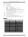
MINIFY
Display duplicated small images. This is the opposite of magnification.
The minification factor sets the number of images in each row/column. A factor of 2 for example puts
four replicated images on each monitor.
Byte
Parameter
Comment
Code
MINIFY
Function code = 104
1
Minification factor
1 - 16
SLIMIT
Sets the overscan limits of minified images. This masks the edge of the image which is not normally
visible since it would be in the overscaned part of the display outside of the visible part of the image.
It can also be used to increase the gaps between the minified images to simulate the physical gaps
between monitors in a conventional videowall.
The mask is applied when the MINIFY command is issued. To change the mask on screen it is
necessary to send the updated limits with SLIMIT and then repeat the MINIFY command.
The colour of the masked area is that set with the COLOUR command (function code 89). In order to
apply this colour the masked area needs to be cleared using the CLEARSCREEN command (function
code 94).
Typical values SLIMIT would be x1 = 0, x2 = 350, y1 = 5, y2 = 287.
Copyright Media Technologies, 1999 – 2006
Page 24 of 61
Brick-2 Videowall Processor Advanced User Guide
Byte
Parameter
Comment
Code
SLIMIT
Function code = 99
1
2
3
4
5
6
7
8
X1 low byte
X1 high byte
X2 low byte
X2 high byte
Y1 low byte
Y1 high byte
Y2 low byte
Y2 high byte
Left Limit
Issue 7
Right Limit
Top Limit
Bottom Limit
For example…
COLOUR 0 0 0
CLEARSCREEN
SLIMIT 0 350 5 287
MINIFY 2
; Set colour in RGB colour space to black
; Set overscan area to colour
; Set blanked overscan area
; Display four minified images
CLEARSCREEN
Clears the overscan area to the colour set using the COLOUR command.
Byte
Parameter
Comment
Code
CLEARSCREEN
Function code = 94
COLOUR CYCLE
Any wash colour associated with each monitor is incremented/decremented by the signed R,G,B
amounts specified, approximately once per video field. Repeating for each of R,G,B until either the
maximum or minimum value is reached, when the direction for that colour reverses.
To terminate a colour wash cycle send the KILL command.
Other commands can be executed while a colour cycle is in progress, but will need to be preceeded by
the IMMEDTATE command. If not they will be queued for deferred execution, and then lost when the
KILL command is received.
Byte
Parameter
Comment
Code
CLRCYCLE
Function code = 105
1
2
3
4
5
6
R speed low byte
R speed high byte
G speed low byte
G speed high byte
B speed low byte
B speed high byte
Signed Red cycle rate +/- 32
Signed Green cycle rate +/- 32
Signed Blue cycle rate +/- 32
Copyright Media Technologies, 1999 – 2006
Page 25 of 61
Brick-2 Videowall Processor Advanced User Guide
Issue 7
SEQUENCE EXECUTION FUNCTIONS
The following commands are used to initiate sequences which have been downloaded to the processor
FLASH memory using the download menu command.
RUN DOWNLOADED SEQUENCE
This command executes a sequence which has previously been downloaded to processor and stored in
FLASH memory.
The file 2:$IRMAP.TXT in the FLASH memory maps the front panel ‘Effect’ switch to sequence file
names. The ‘Effect’ switch returns codes 0 to 15 when the ‘Select’ button on the front panel is pressed.
Other codes can be used to map files to be invoked by this function over the RS-232 control link.
Sequence files can always be executed by name using Function 77.
Byte
Parameter
Comment
Code
IRSEQ
Function code = 75
1
Key-code
ASCII key-code
READ SEQUENCE TERMINATION CONDITION
The reason for termination of a sequence file can be determined using this command.
A non-zero condition indicates either an error or forced termination using Function code 79.
Errors usually occur because a dependent file is missing, e.g. if the INCLUDE command is used and the
file does not exist, or the file name has been entered incorrectly.
Sequences will also terminate if recursive loops are used causing too many files to be opened for
example.
Byte
Parameter
Comment
Code
SEQERR
Function code = 76
Byte
Parameter
Comment
Code
SEQERR
Function code = 76
1
0
1
2
3
4
5
6
7
8
9
Normal termination
Stopped by user (FN 79)
Error reading FLASH
Error opening FLASH file
FLASH file seek error
Illegal function
Function code unsupported
Include name
Include open
Include depth
Returned Data.
Copyright Media Technologies, 1999 – 2006
Page 26 of 61
Brick-2 Videowall Processor Advanced User Guide
Issue 7
RUN SEQUENCE FILE
Executes a sequence file by name.
Sequence files are stored by default in FLASH Sector 3.
Byte
Parameter
Comment
Code
RUNSEQ
Function code = 77
1
2
N-1
N
FLASH Sector
Character string
1 .. 5 (typically 3)
First character
Last character
String termination (null)
0
READ EXECUTING SEQUENCE FILE NAME
Byte
Parameter
Comment
Code
READSEQ
Function code = 78
Byte
Parameter
Comment
Code
READSEQ
Function code = 78
1
2
N-1
N
FLASH Sector
Character string
.
0
1 .. 5 (typically 2)
First character
Last character
String termination (null)
Returned Data.
CANCEL EXECUTING SEQUENCE
Byte
Parameter
Comment
Code
STOPSEQ
Function code = 79
GRAPHICS FUNCTIONS
A limited set of graphics functions are provided. These write pixels directly to the common video frame
store. It is therefore necessary to freeze the image.
Two graphics pages are provided equivalent to the even and odd video fields.
Each page has a set of independent drawing variables:
•
•
•
Drawing colour
Cursor (X,Y)
Font
When page 1 is displayed, page 2 is accessible using the drawing functions and vice-versa.
Both pages can be displayed sequentially as an interlaced full frame picture. This is not generally
recommended as this can introduce a strong flicker.
The frame store holds images in YUV colour space format.
Colours can be specified either in RGB or YUV format.
The nominal displayed image is 720x288 pixels with a 50Hz field rate (PAL/SECAM) or 720x240 at 60Hz
(NTSC). In practice the horizontal pixel range is halved (360) to simplify access to the video memory
Copyright Media Technologies, 1999 – 2006
Page 27 of 61
Brick-2 Videowall Processor Advanced User Guide
Issue 7
which is in YUV 4:2:2 format. Some additional vertical over scan is provided which extends the vertical
range to 300. The accessible range for graphics functions is therefore 360x300. The actual displayed
range depends on the frame rate and amount of over scan on the display monitors. At 360x300
resolution pixels are roughly square.
Text messages in any colour can be displayed over the frozen image. The fonts used are loaded in
FLASH memory.
The font files are present in FLASH Sector 4.
Bit mapped graphics files in two colour '.BMP' format, held in the FLASH memory, can be copied into the
video frame buffer. This feature is useful for displaying small graphic images e.g. company logos.
INITIALISE GRAPHICS
Initialises the graphics system page variables as follows:
Cursor X,Y :
Font
:
Colour
:
0, 0
None
White
Byte
Parameter
Comment
Code
INITGX
Function code = 80
SELECT GRAPHICS PAGE
Selects the graphics page. The Freeze function (44) can be used to the same effect.
Byte
Parameter
Comment
Code
PAGE
Function code = 81
1
1
2
Page 1
Page 2
SELECT FONT
Selects the current font for the selected page. Several fonts are provided as standard, and other fonts
can be downloaded to FLASH if required.
The font for each drawing on each page must be selected independently.
Byte
Parameter
Comment
Code
FONT
Function code = 82
1
1
2
Character string
Page 1
Page 2
First character
Last character
String termination (null)
2
N-1
N
0
Copyright Media Technologies, 1999 – 2006
Page 28 of 61
Brick-2 Videowall Processor Advanced User Guide
Issue 7
PRINT TEXT
Prints a text string at the current cursor location in the current font in the current drawing colour. For
example…
SEND 7 0 FN_PRINT “Message” 0
Byte
Parameter
Comment
Code
PRINT
Function code = 83
1
N-1
N
Character string
.
0
First character
Last character
String termination (null)
DRAW LINE
Draws a line in the current drawing colour to location X,Y from the current cursor location (See also
DRAW LINE RELATIVE).
The current cursor location is updated to X,Y.
If the specified location is outside the drawing area no line is drawn and the cursor remains at the current
location.
For example…
SEND 7 0 FN_LINETO &100 &50
Byte
Parameter
Comment
Code
LINE
Function code = 84
1,2
3,4
X
Y
X location (0..359)
Y location (0..299)
MOVE CURSOR
Moves the cursor to location X,Y if it is within the drawing page limits. See also Function 87.
Byte
Parameter
Comment
Code
CURSOR
Function code = 85
1,2
3,4
X
Y
X location (0..359)
Y location (0..299)
DRAW LINE RELATIVE
Draws a line from the current cursor position to a location relative to the current cursor if the new location
is within the drawing limits.
Byte
Parameter
Comment
Code
RLINE
Function code = 86
1,2
3,4
DX
DY
X offset (+/- 359)
Y offset (+/- 299)
Copyright Media Technologies, 1999 – 2006
Page 29 of 61
Brick-2 Videowall Processor Advanced User Guide
Issue 7
MOVE CURSOR RELATIVE
Moves the cursor to a location relative to the current cursor location. See also Function 85.
If the new location is outside the drawing limits the cursor location is not changed.
Byte
Parameter
Comment
Code
RCURSOR
Function code = 87
1,2
3,4
DX
DY
X offset (+/- 359)
Y offset (+/- 299)
FILL PAGE
The currently selected page is filled with the current drawing colour.
Byte
Parameter
Comment
Code
FILL
Function code = 88
DRAWING COLOUR RGB
Sets the current drawing colour using the RGB colour format.
This is converted to the internal YUV colour format.
Byte
Parameter
Comment
Code
COLOUR
Function code = 89
1
2
3
Red
Green
Blue
Red component 0..255
Green component 0..255
Blue component 0..255
PLOT BITMAP
Plots a two colour (1-bit) bitmap. Pixels in the file set to ‘1’ are written as the current drawing colour.
Pixels set to ‘0’ are unchanged. For example…
SEND 7 0 90 5 “LOGO.BMP” 0
Byte
Parameter
Comment
Code
BITMAP
Function code = 90
1
2
N-1
N
Sector
Character string
FLASH Sector 1..5
First character
Last character
String termination (null)
0
BMP files can be loaded into FLASH memory using the supplied utility FLASH.EXE in the C:\BRICK\EXE
directory.
PUT C:\yourdirectory\yourlogo.BMP 5:MYLOGO.BMP
Installs the file “MYLOGO.BMP” in FLASH sector 5. Names of files stored in FLASH memory are case
sensitive.
To plot pictures with multiple colours, use a photo editor or similar package to separate the colours in
your multiple colour bitmap into separate 1-bit bitmap files and download them separately into the
processor.
Copyright Media Technologies, 1999 – 2006
Page 30 of 61
Brick-2 Videowall Processor Advanced User Guide
Issue 7
Use multiple bitmap commands to overlay them on the display (bitmap commands overwrite previous
bitmaps).
DRAW ELLIPSE
Draws an ellipse centred on the current cursor location.
The horizontal distance from the centre is specified by DX and the height from the centre by DY.
The cursor remains unchanged.
Byte
Parameter
Comment
Code
ELLIPSE
Function code = 91
1,2
3,4
DX
DY
X Radius (0..180)
Y Radius (0..150)
DRAW RECTANGLE
Draws a filled rectangle at the current cursor of length DX and depth DY. The cursor is updated. If the
rectangle extends beyond the drawing limits it is not displayed and the cursor is unchanged.
Byte
Parameter
Comment
Code
RECTANGLE
Function code = 92
1,2
3,4
DX
DY
X length (1..360)
Y length (1..300)
DRAWING COLOUR YUV
Sets the current drawing colour using the YUV colour space as defined in CCIR 601.
Byte
Parameter
Comment
Code
YUVCOLOUR
Function code = 93
1
2
3
Y
U
V
Y component 0..255
U component 0..255
V component 0..255
Copyright Media Technologies, 1999 – 2006
Page 31 of 61
Brick-2 Videowall Processor Advanced User Guide
Issue 7
5 CONTROL SOFTWARE INTRODUCTION
The control software enables all of the hardware features to be configured remotely using a single serial
link between a PC and the processor. It is used to create, maintain and execute video effects sequences.
These may be timed using the PC real-time clock, or synchronised to time codes associated with the
video image using a standard time code reader which can be installed in the PC.
The user interface is graphical and makes use of a mouse which may be a standard 2 or 3 button type.
COMPUTER REQUIREMENTS
The minimum requirements for the computer running the program are:
•
•
•
•
•
•
•
IBM/PC AT compatible, preferably 486 processor, or better
640KB RAM
Hard disk with at least 2 MB free.
One serial port
VGA display
Microsoft compatible mouse
MS-DOS 3.3 or greater.
The program will run under Windows 95, 98, ME, XP and Windows 2000 as an MS-DOS application. It
has also been shown to run on the Macintosh with MS-DOS emulation.
The program requires at least 540kB of main MS-DOS memory to operate reliably.
INSTALLING THE SOFTWARE
To install the software invoke WindowsTM Explorer and double click on the file called 'INSTALL.BAT'
which creates the following directories:C:\BRICK2
EXE
EXAMPLES
FIRMWARE
MANUAL
Edit the batch file to automate installation from disks other than A:\ and for hard disks other than C:\ or
use WindowsTM Explorer to copy all the directories and their contents across to the target drive.
The current version of our control software is DOS based and has been tested to run under the following
TM
versions of Windows including: 95, 98, ME, XP and 2000. It has also been tested on the Macintosh
TM
using MS-DOS emulation. Future versions will be Windows based.
To run the software, create a link on your Windows desktop by right clicking on the desktop and selecting
'new shortcut'.
The executable program is C:\BRICK2\EXE\BRICK2.EXE
The windows default settings should be Ok for running the software.
Choose any WindowsTM icon. After the shortcut is created you can optionally change to the Media
Technologies icon by right clicking on the short cut, select program, select change icon, select browse
and click on our icon file C:\BRICK2\EXE\MT.ICO
Be careful not to run more than one instance of the software or the serial communications will
not work. Close any multiple instances of the software.
A selection of sample effects sequences are provided in C:\BRICK2\EXAMPLES which should be
automatically selected when you first run the software.
On running the software, a graphical screen will appear with menus accessed using the mouse and left
clicking on the buttons as follows.
Copyright Media Technologies, 1999 – 2006
Page 32 of 61
Brick-2 Videowall Processor Advanced User Guide
Issue 7
Select 'SEQUENCES' to see the examples we have provided. If you get the message 'No sequences
defined' use the 'PROJECT' menu to browse the directory structure. You need to click on the file
C:\BRICK2\EXAMPLES\WALL.EFX
The software uses PC port COM1: as the default. If you wish to use COM2: you will need to access the
'CONFIGURE/SERIAL PORT' menu in the software and select COM2:
This selection will be automatically saved ready for next time the software is used.
You can use the 'PROJECT' menu to create your own projects - create another directory, for example
C:\BRICK2\MYSTUFF using Windows Explorer and copy all the files in C:\BRICK2\EXAMPLES across
to this new directory, then using the software, create your own buttons, deleting the examples you do not
want.
RUNNING THE PROGRAM
The program will execute and select the last used project. Communication with the hardware is not
necessary at this stage. Optional command line switches can be appended to the command line:
-r<filename.seq>
-p
: Force execution of 'filename.seq' sequence after start-up
: Do not select last selected project directory
SEQUENCE FILE EXECUTION
If desired the program will execute a named sequence file after start-up. The name of the sequence file
follows the "-r" switch without any space. For example to run the sequence file "DEMO.SEQ" on start-up:
BRICK2 -rDEMO.SEQ
This feature is useful in situations where it is desirable for the videowall to begin execution of a sequence
immediately on power-up without any other manual intervention – say, by incorporating the above
command in the "AUTOEXEC.BAT" file.
Note
It is possible to configure the Brick processor to perform the same function by downloading a
sequence file to FLASH memory and installing it as the "startup" sequence.
DEFAULT PROJECT DIRECTORY
Normally the program will select the last used directory as the default "project" directory. This feature can
be disabled by appending the -p switch to the command line.
BRICK2 -p
Copyright Media Technologies, 1999 – 2006
Page 33 of 61
Brick-2 Videowall Processor Advanced User Guide
Issue 7
6 CONTROL SOFTWARE USER GUIDE
The program is mouse-oriented with pull-down menus. Menus are comprised of a set of graphical button
icons. Active buttons are indicated by a bright central legend.
When the left mouse button is pressed with the mouse over a button icon, the menu option is activated.
The right mouse button is used to exit from menus. It has the same effect as the 'escape' key.
The initial screen consists of 2 buttons across the top line which are always present. A second line of 5
buttons comprise the initial menu. The top-line buttons are:
• Quit
• Help
QUIT
When selected the user is presented with a 'yes'/'no' option. If 'yes' is selected the program terminates
and control reverts to MS-DOS or Windows.
HELP
The help system for the BRICK program is context sensitive. A help file is associated with each menu
level. When help is requested, help text is displayed in a window pulled down below the help button.
INITIAL MENU
There are 5 buttons in the second row of buttons on the initial window which form the top level menu.
They are:
•
•
•
•
•
Video
Project
Split
Sequences
Configure
VIDEO MENU
Selects the video input and output modes:
• Video Input
• Video Output
• Unit ID
UNIT ID
By default the software addresses processor with ID = 0. If more than one processor is connected, by
daisy chaining units together, it is necessary to change the ID used by the software in order to control
one of the other units.
When the Unit ID button is selected, an array of IDs is presented. If one of these, other than zero is
selected a window in the title bar will display the selected unit ID. All commands issued by the PC
software will now use that address.
Some menu options in the PC control software make use of global addresses and will therefore control
all units simultaneously irrespective of their IDs, e.g. setting the overall split.
VIDEO INPUT MENU
This allows the contrast, brightness etc. to be remotely adjusted. Settings can be stored remotely in
FLASH memory or saved in a notepad file for inclusion in a sequence file.
Copyright Media Technologies, 1999 – 2006
Page 34 of 61
Brick-2 Videowall Processor Advanced User Guide
Issue 7
The following features are provided.
INPUT CHANNEL
Selects one of either of the two digitisers available in the Brick processor.
COLOUR SYSTEM
Enables the colour system to be set for the selected input channel. Four options are available:
•
•
•
•
PAL
NTSC
SECAM
AUTO
The selection of PAL/SECAM on the primary video input channel also selects 50Hz frame rate
processing in the pixel replication logic.
Selecting NTSC configures the processor for 60Hz frame rate processing in the pixel replication logic.
The AUTO button allows automated selection between NTSC and PAL based on the input signal to
Video Input Channel-1.
If a valid signal is detected when the AUTO button is highlighted the PAL or NTSC button will be
highlighted as detected by the processor, and the processor configured automatically for either PAL or
NTSC (50Hz or 60Hz) operation.
VIDEO INPUT SOURCE
Sets the video input signal type and video levels.
There are three possible sources for each input channel…
•
•
•
C-Video Input-1
C-Video Input-2
S-Video
Each input is independent, therefore it is possible to have different sources on the Composite Video and
S-video inputs of either channel, and switch between them.
The sliders set the Brightness, Saturation, Contrast and Hue levels.
SAVE IN FLASH
This button will write the current settings into a file in the FLASH memory system (for both channels). If
this button is not pressed, the processor will revert to the previously saved settings on power-up.
VIDEO OUTPUT MENU
This allows the output video mode to be selected.
The following configurations are provided:
•
•
•
•
•
•
•
S-Video
Composite-Video
Dual Composite-Video
Interlaced
Non-Interlaced
Bars
Filter
Copyright Media Technologies, 1999 – 2006
Page 35 of 61
Brick-2 Videowall Processor Advanced User Guide
•
Issue 7
Save in Flash
DUAL COMPOSITE VIDEO MODE
Selects Composite-Video output mode on both signal pins of the S-Video connector.
These Composite-Video outputs will be identical except they are individually buffered to allow driving of
two videowall arrays without degrading the signal levels and avoiding the expense of video distribution
amplifiers.
INTERLACED
Every incoming video field is displayed, may result in flicker if a lot of text or horizontal features present
in the video source material.
NON-INTERLACED
Alternate incoming video fields are displayed, reduces flicker if a lot of text or horizontal features are
present in the video source material.
BARS
Switches the display to colour bars (ON / OFF).
FILTER
Controls the pixel interpolation mode (ON / OFF / PARTIAL). This function is not implemented in current
firmware versions. Contact us for availability.
SAVE IN FLASH
This button will write the current settings into a file in the FLASH memory system (for both channels). If
this button is not pressed, the processor will revert to the previously saved settings on power-up.
SPLIT MENU
The SPLIT menu allows different splits to be configured on the array.
This setting over-rides the switch on the processor front panel, but the processor will revert to the default
value on the panel switch value on power-up.
PROJECT MENU
A project is a sub-directory containing sequences files, (".SEQ") sub-project files (".EFX") and data files
containing the non- default configuration data.
The file which defines the sequence file buttons is called by default "WALL.EFX" Additional files with the
extension ".EFX" can be used for further sub-projects in the project directory. The default settings and
wall dimension will be the same for all ".EFX" files in a sub-directory.
The initial project selected will be set to the last used project on start-up unless the -p switch is used to
suppress this feature, in which case a file "WALL.EFX" in the current directory is used.
To select a new project enter the directory and path name after the 'New project: ' prompt and press
return.
To leave without changing the current project directory simply press return, or 'click' on the 'CANCEL'
button.
If you wish to browse the directory to search for an existing project file, click on the 'BROWSE' button.
This will pull down a window containing a list of current ".EFX" files, MS-DOS sub-directories and disk
drives. The 'UP' and 'DN' buttons page the directory listing in the window.
Copyright Media Technologies, 1999 – 2006
Page 36 of 61
Brick-2 Videowall Processor Advanced User Guide
Issue 7
Clicking on the text in the window will select the file or sub-directory/drive. If the selected item is a subdirectory/drive the directory will be re-listed with the new path. To use the selected file click on 'OK'. This
will place the full file path name in the text buffer and close the window.
If a sub-directory instead of a file is specified the filename "WALL.EFX" is assumed. If the project
directory selected is new, a prompt will appear querying whether the current project system files should
be copied to the new one.
The system files are…
WALL.EFX
WALLDIM.INC
WALLED0.MAC
Note: Not all of these files will necessarily exist in a given project directory.
SEQUENCE MENU
When the 'SEQUENCE' button is selected the sequence file control panel will be displayed. This contains
a double row of control buttons above a field of sequence buttons that relate to the user's sequence files.
These sequence files contain the commands necessary to execute a timed sequence of effects on the
wall.
Using the upper rows of control buttons it is possible to add, delete, and edit the sequence files, and alter
the position and page on which the sequence buttons appear.
Copyright Media Technologies, 1999 – 2006
Page 37 of 61
Brick-2 Videowall Processor Advanced User Guide
Issue 7
SEQUENCE COMMAND SUMMARY
The command format of the sequence files is described in a separate section of this manual.
The following is a summary of the available commands.
INCLUDE
EXIT IF
DEFINE
FORGET
PROC
ENDPROC
SEND
OUTPUT
WAIT
REPEAT
AGAIN
UNTIL
REM
SPEED
POLL
RADIX
SHELL
EXEC
END
Includes text from another file in the current file.
Terminate an 'include' file if a macro name is defined
Define macro text substitution.
Delete a macro/procedure.
Procedure definition.
Marks the end of a procedure.
Sends a single protocol command.
Outputs unstructured bytes directly to the serial port.
Waits for a period (relative to PC clock or time code)
Loop construct, start.
Loop construct termination.
Conditional loop construct termination.
Issue a comment to PC screen scrolled in a window.
Change serial port speed.
Request data from the hardware.
Change the default number base.
Use MS-DOS command shell to execute a MS-DOS program.
Suspend the software and execute a MS-DOS program
End of file delimiter.
ADD
Before a sequence file itself can be created using the editor directly, a button must created using the
'ADDSEQ' option.
The button definition has two parts as follows.
LEGEND
FILENAME
: The name that will appear on the button.
: The sequence file associated with the button.
Both the legend and the filename must be defined. A filename may be automatically generated by
clicking on the 'AUTO' button.
Sequence files have the extension type ".SEQ". If an extension is not used the program will
automatically append ".SEQ" to the filename. The file does not have to exist before it is associated with
the button.
A single sequence file can be invoked by any number of buttons.
DELETE
When selected any sequence button when 'clicked' will be deleted with (optionally) the associated
sequence file.
EDIT
The Editor is invoked by selecting 'EDIT' on the toolbar menu and then 'clicking' on a sequence button.
The file associated with the button will be loaded into memory and the editor window opened. To leave
the Editor click on 'EXIT'. If you wish to abandon changes to a file without leaving the Editor click on
'CANCEL'.
Button assignments for the editor are as follows.
Copyright Media Technologies, 1999 – 2006
Page 38 of 61
Brick-2 Videowall Processor Advanced User Guide
Pg-Up
Scrolls up one page.
Pg-Dn
Scrolls down one page.
Up
Scrolls up one line.
Dn
Scrolls down one line.
File
File presents a menu with three options:
FILE
MERGE
SAVE
Cut
Issue 7
: Open a new file
: Merge an existing file at the current cursor position.
: Update file with latest edits.
Cut a block of text lines and save in a temporary buffer. To select the lines move the
cursor to the start line then press and hold the left mouse button. Move the cursor to the
end of the block and release the mouse button.
The selected block will be highlighted. Select 'Cut' to delete and save it in the buffer.
Copy
As 'Cut' but the selected blocks are not deleted.
Paste
Copies the previously selected block to the file at the current cursor location.
Find
Find a string in the current file.
Line
Move the cursor to a selected line number.
Cancel
Cancel any changes since the start of editing the current file.
Exit
Leave the editor. If the file has changed a dialogue box will appearing allowing the file
to be saved before exit, to exit with no changes, or to return to the editor.
CONTROL KEYS
Editor control key functions are as follows.
Control + Key
^R
^C
^QR
^QC
^S
^D
^E
^X
^V
^G
^H
^I
^W
^Z
^T
^Y
^U
^L
^N
^QF
^QI
Function Key
Pg-Up
Pg-Dn
Home
End
Ctrl + Home
Ctrl + End
Left arrow
Right arrow
Up arrow
Down arrow
Insert
Delete
Backspace
TAB
ESC
Action
Page up
Page down
Start of line
End of line
Top of file
End of file
Cursor left
Cursor right
Cursor up
Cursor Down
Insert mode On/Off
Delete character
Cursor left + delete character
Tab (4 spaces)
Exit editor
Scroll window up
Scroll window down
Delete word left
Delete line
Undelete line
Search next
Insert new line
Search
Go to line number
Copyright Media Technologies, 1999 – 2006
Page 39 of 61
Brick-2 Videowall Processor Advanced User Guide
Issue 7
MACRO BUTTONS
If the '#' button at the top right of the editor screen is clicked a column of 'macro' buttons will appear.
At the top of the column is the 'Notepad' button. If this is clicked, the contents of the notepad will be
copied to the file.
The notepad holds temporary data generated from the effects windows.
The remaining buttons are defined in a macro file called "WALLED0.MAC" which can contain up to 10
macro lines.
The format for these files is…
"Macro text.... ", buttonlegend
"@filename"
, buttonlegend
Where 'Macro text' is any text string and 'Buttonlegend' is the legend to appear on the associated button.
If the first character of the macro text is an '@' then the text is treated as a filename which will be
merged when the macro button is pressed.
A "WALLED0.HLP" file is associated with the macro file. If such a file exists, with the MACRO buttons
displayed, the contents of the help file will be displayed when the 'HELP' button is selected. If not, the
normal editor help file will be displayed.
DOWNLOAD
Sequences may be down loaded to the embedded system controller to be stored in FLASH memory and
subsequently executed directly on the system.
Important Note:
The download-sequence compiler does not currently support all the sequence commands
available, and 'WAIT' commands are relative to the PC time clock.
In the current software, procedures can only be used without parameters.
When 'Download' is selected and a sequence button is then selected, the sequence compiler will be
invoked. If the sequence compiles successfully it is downloaded into the FLASH memory.
The current contents of the FLASH memory can be displayed by selecting 'List' in the 'Controller' menu,
which is itself located in the 'Controls' menu.
The name of the FLASH file is the same as the first 8 characters of the MS-DOS filename but with the
extension ".SFB".
Note:
Each sequence filename in the FLASH memory must be unique.
PROJECT
The 'Project' button at this menu level has the same effect as the 'Project' button from the top level
menu.
RENAME
A selected sequence button can be renamed. Both the legend on the button and the associated
sequence file may be changed.
Copyright Media Technologies, 1999 – 2006
Page 40 of 61
Brick-2 Videowall Processor Advanced User Guide
Issue 7
CUT
When selected, any sequence button can be temporarily deleted and saved. The 'Paste' mode will then
be automatically selected. The button may then be 'pasted' back in any position by clicking in the
appropriate place. The page may be changed while in paste mode.
Only one button may be 'Cut' at a time. If a second button is cut, it will replace the earlier one.
PASTE
If a button has previously been 'Cut', selecting 'Paste' will allow it to be pasted back onto the page. The
button may then be pasted back in any position by clicking in the appropriate place. The page may be
changed while in paste mode to transfer or replicate the button on another page.
EXIT
Leaves the 'Sequence' menu. If there were any changes made to sequence buttons a prompt will be
displayed requesting confirmation whether or not the changes are to be made permanent.
The sequence menu (and all menus) can also be exited by right clicking on the mouse.
CONFIGURE MENU
The configure menu pulls down a further set of buttons as follows.
•
•
•
•
•
•
•
Controller
Unit ID
Serial Port
Firmware Update
Hardware Reset
Alignment
Program info
CONTROLLER MENU
Selects the System Control function, from which sequences installed in the Brick’s FLASH memory can
be listed and executed. The following functions are are available from the controller menu.
•
•
•
•
•
•
•
•
Keypad
Run
Stop
List
Delete
Startup
Show
Map
KEYPAD MENU
Brings up a keypad to enable downloaded sequences mapped to key numbers to be run.
RUN MENU
When selected a menu of installed sequences in FLASH memory will be displayed. If a file is selected if
will execute on the processor independently of the PC.
STOP MENU
When selected stops any executing sequence running remotely on the Brick processor.
Copyright Media Technologies, 1999 – 2006
Page 41 of 61
Brick-2 Videowall Processor Advanced User Guide
Issue 7
LIST MENU
Produces a list of currently installed sequences and shows the file sizes. This assumes that sequences
are stored in Sector 3 of the FLASH filing system. This is the case for all sequences stored using the
graphical interface which always assumes Sector 3.
It is possible using the FLASH.EXE utility to store sequence files in other sectors.
DELETE MENU
Brings up a list of sequence files. If a file is selected, then it will be deleted when OK is pressed.
STARTUP MENU
Brings up a further menu which allows a specific sequence stored on the PC to be installed as a special
sequence file to be run on power-up. The file can also be deleted, and executed from this menu. By
pressing “Execute” the sequence can be invoked without resetting the unit, to test it for example.
SHOW MENU
Shows the filename of the currently executing sequence or “none” if no sequence currently running.
MAP MENU
An editor is invoked to edit a text file stored in FLASH memory that maps the front panel ‘Effect’ switch
to a particular downloaded file. The format of this mapping file follows.
<keycode> = sequence.sfb
The downloaded effects can be invoked manually using the front panel ‘Effect’ switch and pushing the
"Store ID" button.
If the mapping file does not exist in the processor FLASH, a blank file is automatically created for
editing. Additional mappings can be included using key code 16 to 255. These can only be invoked using
a command via the serial link.
A sample file is provided on Sequence Page 10 of the software examples.
UNIT ID
By default the software addresses processor with ID = 0. If more than one processor is connected, by
daisy chaining units together, it is necessary to change the ID used by the software in order to control
one of the other units.
When the Unit ID button is selected, an array of IDs is presented. If one of these, other than zero is
selected a window in the title bar will display the selected unit ID. All commands issued by the PC
software will now use that address.
Some menu options in the PC control software make use of global addresses and will therefore control
all units simultaneously irrespective of their IDs, e.g. setting the overall split.
SERIAL PORT MENU
This button selects COM1: or COM2: to be used by the software. The selection will be automatically
saved ready for next time the software is used.
FIRMWARE UPGRADE MENU
New firmware can be downloaded to the Brick processor using this menu option. Detailed use of this
facility will be described in the documents shipped with firmware upgrades.
When selected, a prompt appears for a file containing the binary image of the new firmware. The path
and filename can be entered directly, or the Browse button pressed to locate the desired file. Once
selected, download begins when OK is pressed. To abandon download press cancel.
Copyright Media Technologies, 1999 – 2006
Page 42 of 61
Brick-2 Videowall Processor Advanced User Guide
Issue 7
The DOS file selected will always be renamed to SYSTEM.COM in the FLASH filing system. A file of this
name will usually exist, in which case a prompt will appear warning that this is about to be overwritten. If
‘Yes’ is pressed, download will proceed over writing the existing SYSTEM.COM file.
As the download progresses a thermometer style display will indicate progress.
Once firmware download is completed it is necessary to reset the unit to run the new code.
IMPORTANT
If for any reason the download fails do not reboot the processor - start the download again.
If the processor has been rebooted without properly upgrading the code it will fail and then it is
necessary to use the boot failure recovery procedure described in a separate section.
HARDWARE RESET MENU
This button sends a global system reset command to the hardware. Before the command is sent a 'Yes
or No' confirmation dialogue box will appear. The reset command will be sent if 'Yes' is selected. The
hardware reset operation will take a few seconds to complete.
ALIGNMENT MENU
This menu option presents an alignment adjustment screen. This shows graphically the monitor channel
numbers and their position in the wall. A row or column can be selected using the letter/number boxes on
the Top and Left of the wall representation. Once selected the Adjust slider can be used to move the row
or column in relation to the other monitors.
This procedure should only be used after all of the videowall monitors have been aligned individually to
compensate for under or over scanning of the magnified fragments displayed on the monitors.
Once the wall has been aligned the settings can be saved in FLASH memory to be automatically applied
on start-up. It is also possible to save the settings in text to the notepad for subsequent inclusion in a
sequence file.
The image on the wall is by default a magnified image. If the ‘Test Pattern’ button is pressed a pattern
which identifies the channel and draws a line from opposing corners of each monitor is displayed, to
assist in aligning the image.
Pressing the VIDEO button will cause the input video signal to be displayed.
You can select 2x2, 3x3 or 4x4 magnification mode by pressing the appropriate buttons on this menu
page.
PROGRAM INFORMATION
This is a software maintenance facility which shows the amount of free memory and free file capacity. It
also displays the program version number.
Copyright Media Technologies, 1999 – 2006
Page 43 of 61
Brick-2 Videowall Processor Advanced User Guide
Issue 7
7 CREATING SEQUENCES
The ‘BRICK2.EXE' videowall control program includes a real-time sequence control language. Video
effects are invoked using timed sequences of commands to the hardware. The language commands are
held in standard ASCII text files. The sequence files may be created with the integrated editor or an
external text editor/word processor.
Control commands are decoded and sent as messages to the hardware via the PC serial ports.
The control language uses a basic command and parameter list format. A simple line based macro
processor is included. In the descriptions of the commands uses a simple language notation. Optional
parameters are contained in square brackets. A parameter which must be one of a set is indicated by the
set enclosed in curly brackets, each parameter separated by a vertical bar. Numeric parameters are
contained in angle brackets. Parameters are separated by commas.
SEQUENCE FILE FORMAT
Each line of the command file consists of either a blank line, a comment, or a command. Only one
command may be invoked per line. Most commands are followed by a variable length list of parameters
dependent on the command type.
Numeric parameters can be in either decimal, hex, or binary. Hex numbers may be represented in either
the 'C' format as 0xnn or the 'assembler' format using a leading decimal digit and trailing 'H' Binary
numbers are designated by a trailing 'B'. Any number may have leading zeros. Unlike 'C' this does not
designate base 8. Hex numbers may use upper or lower case letters. For example…
Decimal
16-bit Decimal
Binary
8-bit Hexadecimal
16-bit Hexadecimal
:
:
:
:
:
255
&16430
11111111B
0xFF, 0x0ff or 0FFH
&0x800F
All commands and parameters should be delimited by a space, comma, or tab character.
The default base may be changed using the RADIX command to any base from 2 to 16.
Macros may be defined to substitute text strings with key words.
Command words can be in either upper or lower case.
Macros are case sensitive
Command lines before and after macro expansion must be less than 132 characters.
COMMAND DEFINITIONS
The following commands are implemented.
PAL and NTSC
When compiling sequences to be downloaded to FLASH memory in the processor for stand alone
operation, the compiler must adjust the number of video fields counted in ‘WAIT’ commands, to ensure
that time delays are equivalent for both PAL (50 Hz) and NTSC (60 Hz) operation.
Normally, the appropriate sequence command ‘PAL’ or ‘NTSC’ is included at the beginning of the
STD.INC file depending on the country where the system was purchased.
In the event that it is required to operate in PAL mode in an NTSC country, the user should create a
version of STD.INC with the command ‘PAL’ substituted for the command ‘NTSC’, and vice-versa.
Copyright Media Technologies, 1999 – 2006
Page 44 of 61
Brick-2 Videowall Processor Advanced User Guide
Issue 7
INCLUDE
The include command 'includes' text from another file in the current file.
Command syntax is.
INCLUDE { <filename.typ> | ["][d:][\path\]filename[.typ]["] }
The INCLUDE command has one parameter, either a filename in angle brackets or a conventional MSDOS filename. Quotes are optional on the conventional filename. Included filenames in angle brackets
are prefixed by the MS-DOS environment variable VIDEOWALL.
For example in the system AUTOEXEC.BAT file the SET command may be used to prefix all the SEND
program include files enclosed in angle brackets with the subdirectory C:\BRICK using the following
format.
SET VIDEOWALL=C:\BRICK2
Conventional filenames without the angle brackets can optionally have drive letters, path descriptions
and file types.
Includes can be nested to a depth of 10. The nesting depth is the only method by which recursive
includes are trapped. Files may be 'included' at any point in a command file.
The file STD.INC is a special case. If a file of this name is found in the current directory it will be
included before the sequence file is executed. If not, the directory defined using the VIDEOWALL
environment variable will be searched.
SEND
The SEND command sends a single command to the processor. The send command expects at least 3
parameters. (See the hardware interface description for details of commands.)
Command syntax is as follows.
SEND <p1>,<p2>,<p3> [,<p4> .. <pN>]
The parameters p1 to pN are numbers in the range 0 - 255. A parameter from p4 onwards may be
preceded by the '&' character to force it to occupy two bytes, LSB first.
The first 3 parameters common to all SEND commands are as follows.
p1 = Module type.
p2 = Module address.
p3 = Message function code.
Module type is a number with the following allocation,
0-6
7
: RESERVED
: BRICK PROCESSOR
The module address is a number from 0 to 255. A macro “_UNIT” may be used instead, which
substitutes the currently selected unit address from the UNIT ID menu.
The message function code is decoded by the addressed module which executes the function using any
parameters which follow.
The Brick series processors have no internal modules so requires only one sub-address. By default this
is zero. If additional processors are used, e.g to provide full frame splits greater than 5x5, each
processor needs to be allocated a unique address. If the processors are ordered with this intention, they
will be supplied pre-configured.
Copyright Media Technologies, 1999 – 2006
Page 45 of 61
Brick-2 Videowall Processor Advanced User Guide
Issue 7
Parameters p4 to pN are placed in the data bytes section of a message. An ASCII text string can be used
in the parameter list.
Each character of the string will be converted to a number in the range 32..127 and used in the same
way as numeric parameters.
OUTPUT
The OUTPUT command is a lower level version of the SEND command. It will send any number of
parameters supplied as bytes to the hardware (limited by the maximum line length) without formatting
the data into a structured message.
Command syntax is...
OUTPUT <p1> [<p2> .. <pN>]
A parameter may be preceded by the '&' character to force it to occupy two bytes, LSB first. ASCII
strings may be sent by enclosing them in double quotes, For example:
OUTPUT "PLAY",0x0D
WAIT
This is the primary time dependent command word. Parameters supplied determine whether the control
program will wait for a set period, until the elapsed time since the start of the file, the absolute time or on
reaching a time code for the selected video source. (Note: Use of time codes requires a compatible time
code reader to be installed in the PC).
Command syntax is as follows.
WAIT [{FOR | UNTIL | TIMECODE | ELAPSED}] <time> [,<offset> [,<rate>]]
<time>
<offset>
<rate>
= hh:mm:ss[{.dd|:ff|-ff}] (dd = decimal fraction, 01..99)
= hh:mm:ss[{.dd|:ff|-ff}] (ff = Fields 1..24 for PAL)
= 0..65535
The default if no sub-command is supplied is the same as FOR.
The time and offset are defined in 24 hour clock format, hours, minutes, seconds and optionally
hundredths of a second if a dot is used to separate the seconds or fields if a colon or dash is used.
There are 25 fields per second for PAL and 30 for NTSC.
The actual time is calculated by multiplying the rate and offset then adding this to the base time and
compensating according to the PAL or NTSC command included in the STD.INC file. See also the PAL
(NTSC) command.
The offset and rate are optional. These are mainly used in loops, for example:
REPEAT 9
SEND BRICK,@i,EFFECT,P1,P2
WAIT TIMECODE 0:0:10,0:0:1,@i
AGAIN
; Prime hardware with an effect
; Wait at time codes 0:0:10,0:0:11 etc.
WAIT FOR
The WAIT FOR subcommand will wait for the selected time on decoding the command.
If any key on the keyboard is pressed the wait command will terminate.
Copyright Media Technologies, 1999 – 2006
Page 46 of 61
Brick-2 Videowall Processor Advanced User Guide
Issue 7
WAIT ELAPSED
The WAIT UNTIL subcommand will wait until the elapsed time from the start of the command file is
greater than the time defined.
If any key on the keyboard is pressed the wait command will terminate.
WAIT UNTIL
The WAIT UNTIL subcommand will wait until the absolute time (PC Clock) is greater than the time
defined.
If any key on the keyboard is pressed the wait command will terminate.
WAIT TIMECODE
The WAIT TIMECODE subcommand will wait until the time read from the time code reader is greater
than the time parameter.
If any key on the keyboard is pressed the wait command will terminate.
If a time code reader is not installed an error message is issued and command file interpretation is
aborted.
DEFINE
Macros can be defined, using the DEFINE command, which will be expanded on a line by line basis
when encountered.
Command syntax is…
DEFINE NAME [=] text....
The macro NAME can have up to 16 characters.
There is no restriction on the characters of the macro name apart from delimiters space, tab and comma.
Macros are expanded as they are encountered in the input file by the command processor except if they
are parameters to a macro definition.
Macros must be defined before they can be used.
The macro text can comprise delimited parameters. A simple parameter substitution mechanism is
provided. This allows up to 9 parameters in the text portion of the macro definition to be undefined.
These are designated by a question mark followed by a decimal digit in the range 1 to 9.
Parameters following the macro name on expansion will be substituted in the order defined by the
number following the question mark.
For example the macro defined like this…
DEFINE SWAP = ?2,?1
On expansion, will reverse the parameters supplied, so that for example…
OUTPUT SWAP 200,100
Expands to…
OUTPUT 100 200
Macros can be nested to any depth, but on expansion the line length must not exceed 132 characters.
Copyright Media Technologies, 1999 – 2006
Page 47 of 61
Brick-2 Videowall Processor Advanced User Guide
Issue 7
Macro expansion is dependent to a certain extent on the command - commands such as SHELL and
EXEC will stop macro expansion as soon as the command word is decoded. This is particularly true in
the case of the DEFINE command itself.
For example…
DEFINE ONE 1
SHELL ONE
; Define macro with value of 1
; ONE is used directly and not converted
DEFINE NEWSHELL SHELL
NEWSHELL ONE
; Redefine SHELL command
; Macro expansion takes place to give: SHELL 1
FORGET
Macros and procedures can be deleted from the symbol table at any point in the file using the FORGET
command. If previously defined macros depend on the macro that has been deleted they will cause
errors on expansion later.
Command syntax is…
FORGET name
PROCEDURES
Procedures are similar to macros in many ways except that they span more than one line and may
contain a number of commands. Up to 9 parameters can be passed to each procedure. The procedure is
defined starting with the PROC keyword and terminates with the ENDPROC keyword. Both keywords
must be on a separate line.
Command syntax is…
PROC name [p1 .. pn]
.
Commands
.
ENDPROC
Procedures can have up to 9 parameters. These can be used to substitute parameters to commands
within the body of the procedure, or passed as further parameters to procedures calls within the
procedure body.
For example…
PROC EFFECT start,middle,finish
SEND 7 0 1,2,start
SEND 7 0 1,2,middle
SEND 7 0 1,2,finish
; Procedure EFFECT with 3 parameters
; Use each parameter in turn for the
; same basic command
ENDPROC
; End of procedure
EFFECT 1,2,3
EFFECT 4,5,6
; Execute procedure
; Again with different arguments
The dummy arguments: 'start, middle, finish' define the number of parameters the procedure will accept.
When the procedure is used the number of parameter arguments supplied is checked.If the wrong
number of parameters is supplied an error message is displayed and execution stops.
Copyright Media Technologies, 1999 – 2006
Page 48 of 61
Brick-2 Videowall Processor Advanced User Guide
Issue 7
REMARKS
The REM command allows remarks to be displayed on the PC screen as the commands are sent to the
processor. All the text following the REM statement is displayed on the screen. As soon as the macro
expander recognises the REM command, macro expansion ceases.
In addition a number of escape codes are provided as follows.
@t
@d
@s
@e
@f
@r
@b
Current system time.
Current system date.
File start time.
Elapsed time.
The current sequence file name.
Read and insert current time code from time code reader (if installed).
Bell character.
Two further escape codes may be used in REM commands to show the two innermost loop counts
generated by the REPEAT command.
@i Inner loop count
@j Second level loop count
REPEAT
Command syntax is.
REPEAT [FOREVER | <n>]
The REPEAT command marks the beginning of a program loop.
REPEAT commands must be matched by a corresponding AGAIN or UNTIL command.
An optional loop count can be supplied. If a loop count is not supplied, FOREVER is assumed.
A loop can be terminated using a parameter to the UNTIL command even if it is started with a REPEAT
FOREVER command.
For example…
REPEAT 20
.
Commands on any number of lines
.
AGAIN
Or...
REPEAT FOREVER
.
Commands in loop
.
UNTIL TIMECODE = 00:20:00
REPEAT commands can be nested to any depth limited only by availability of PC memory.
For example…
REPEAT
REPEAT 20
.
Commands
.
; Start of outer loop
; Repeat a sequence 20 times
; Commands comprising the sequence
Copyright Media Technologies, 1999 – 2006
Page 49 of 61
Brick-2 Videowall Processor Advanced User Guide
AGAIN
UNTIL TIMECODE 0:0:10
Issue 7
; Loop back to nearest REPEAT
; Keep going until timecode is passed
Two special macros are provided which are converted to the current loop index when used. These
special macros are @i and @j.
The following shows the format.
REPEAT 3
REPEAT 3
REM Loop = @j,@i
AGAIN
AGAIN
This double loop will display in a window the following messages…
Loop = 1,1
Loop = 1,2
Loop = 1,3
Loop = 2,1
(etc... until)
Loop = 3,3
These special macros can be used as parameters to macros and procedures.
AGAIN
This command marks the end of a looping program block.
REPEAT command.
There are no parameters. See above
UNTIL
The UNTIL command marks the end of a sequence loop.
The loop is repeated conditionally with one of three conditions: TIMECODE, ELAPSED, or LOOP.
Command syntax is.
UNTIL [ TIMECODE[ = ] hh:mm:ss[ {.dd|:ff|-ff} ] ]
UNTIL [ ELAPSED [ TIME[ = ] ] hh:mm:ss[ {.dd|:ff|-ff} ] ]
UNTIL [ LOOP [TIME[ = ] ] hh:mm:ss[ {.dd|:ff|-ff} ] ]
TIMECODE is followed by time parameters.
The loop will continue until the current time code is greater than the time code parameters specified.
ELAPSED TIME is followed by time parameters.
The loop will continue until the elapsed time since the start of execution of the file is greater than the
time parameter.
UNTIL LOOP TIME is also followed by time parameters.
This will loop until the elapsed time since the start of the loop is greater than the supplied time
parameter.
SPEED
This command can be used to change the baud rate of the serial communications port.
Copyright Media Technologies, 1999 – 2006
Page 50 of 61
Brick-2 Videowall Processor Advanced User Guide
Issue 7
By default this is 19,200. If other devices are connected to the same port it is possible to send
commands to them using the OUTPUT command to build the command messages and SPEED to select
the correct transmission rate.
Command syntax is.
SPEED <rate>
The rate parameter can be any rate supported by a PC up to 19,200. Typical rates are as follows.
300, 600, 1200, 2400, 4800, 9600, 19200
The data format is.
8 data bits, 1 stop bit, with no parity.
POLL
Command syntax is.
POLL <card>,<address>
This command requests information from hardware.
If the POLLed device has any data ready for transmission it will be returned on receipt of this command.
Devices will only have data if they have been sent a command previously requesting it.
If no data is ready a 'NULL POLL' message will be returned.
There will be no displayed information in response to 'NULL POLL'
If the device addressed does not exist then after a short time-out period a message will be displayed
showing that the POLL command failed.
Returned messages are defined in the device-specific documentation.
RADIX
Normally the SEND program uses decimal numbers by default. This may changed using the RADIX
command to any base from 2 to 16.
The base selection parameter is always in decimal regardless of the current radix.
Command syntax is.
RADIX <n>
For example to select HEX as the default base…
RADIX 16
SHELL
This command executes an MS-DOS command using the MS-DOS command shell interpreter.
Control reverts back to the BRICK program on completion, not the MS-DOS command line.
SHELL expects a string which is passed to the MS-DOS command shell.
On return the serial port is reset and the transmission rate is set to the default rate of 19200 baud.
For example to display the current directory…
Copyright Media Technologies, 1999 – 2006
Page 51 of 61
Brick-2 Videowall Processor Advanced User Guide
Issue 7
SHELL DIR *.* /w
Or using a MACRO...
DEFINE FILES SHELL DIR C:\WALL\*.SEQ /W
....
FILES
The SHELL command should not be used if the program requires any keyboard input because the output
is held in a temporary file and only displayed in a window when control reverts to the BRICK program.
Any keyboard input would not be echoed back to the user until the program ended.
Also the SHELLed program must not change the video mode of the screen otherwise the control
software display will be corrupted.
Programs which require input or write directly to the screen can be executed directly from the control
software using the EXEC command.
EXEC
This command completely suspends the BRICK program and executes the specified MS-DOS
command. The screen contents are saved.
This command allows programs such as word processors that will reconfigure the screen to be executed
from a button. For example to execute WORDPAD…
EXEC WORDPAD
END
This command will terminate sequence file execution. Any succeeding commands will be lost. This has
the same effect as an end of file and is therefore optional.
This command should not be used in procedures.
EXIT IF
This command enables ‘include’ files to be 'included' more than once without causing re-definition errors,
a conditional EXIT command is provided.
Command syntax is.
EXIT IF [ DEFINED ] symbol
If the symbol is already defined 'including' is abandoned and control continues from the 'calling' file.
For example…
EXIT IF FRED
DEFINE FRED = 1
COMMENTS
Comments can be included either on a blank line or at the end of a command line by preceding the
comment with a semicolon.
Commented lines must be less than the line maximum of 132 characters.
Blank lines and spaces may be freely spread throughout a command file to improve readability.
Copyright Media Technologies, 1999 – 2006
Page 52 of 61
Brick-2 Videowall Processor Advanced User Guide
Issue 7
8 DOS COMMAND LINE EXECUTION
A version of the control software - SEND.EXE - is provided which provides control of the hardware in
MS-DOS batch files.
Control commands are decoded and sent as messages to the hardware using the COM1: or COM2:
serial ports.
The language of the control file uses a basic command and parameter list format. A simple line-based
macro processor is included.
The contents of the sequence files used by the SEND program are the same as those used in the control
software but without the overhead of the graphical user environment. See previous section.
COMMAND LINE INVOCATION
SEND expects at least one argument: the command file to send. If no filename is supplied a short
prompt message will appear such as:
Video Wall command file processor. Version 2.0 Aug 18 1999
(c) Copyright Media Technologies, 1991 – 2004.
Use the following format.
SEND { filename.typ[ -e | -t | -v ] } | {-I } [ -l ] [ -s ] [ -o ] [ -com1: | -com2: ] [ -b<rate> ]
Where the parameters are.
-e
-t
-v
-I
-l
-s
-o
-com1:
-com2:
-b<rate>
Macro expansion mode.
Test expansion mode.
Verbose execution mode.
Interactive execution mode.
Log I/O to files TX.LOG & RX.LOG
Suppress automatic use of STD.INC
Reserved
Use serial port 1
Use serial port 2
Set speed of selected serial port
If a filename is supplied without any switches, SEND will sequentially process the file sending commands
to the device. No output will appear on the PC screen except for the output from 'REM' commands. This
is the normal execution mode.
SEND can be used additionally with one of four possible switches to select further operational modes
described below.
TEST MODE [ -t ]
In this mode SEND will show each stage of the macro expansion process and the final bytes in HEX that
would be sent to the processor. No actual data is sent and the 'WAIT' command is ignored.
MACRO EXPANSION MODE [ -e ]
In this mode SEND will expand all macros to reduce the source file to its simplest form. All comments
and blank lines are removed. The reduced output is sent the MS-DOS console device and so may redirected to file using the '>' redirection facility of the MS-DOS command shell. No data is sent to the
processor.
Copyright Media Technologies, 1999 – 2006
Page 53 of 61
Brick-2 Videowall Processor Advanced User Guide
Issue 7
VERBOSE EXECUTION MODE [ -v ]
This mode is much the same as normal execution mode except that the lines of the command file are
displayed as they are interpreted. When a 'WAIT' command is encountered a wait prompt message is
issued causing the command to be displayed.
INTERACTIVE MODE [ -i ]
In this mode the source text is taken from the keyboard instead of a file.
Unlike the previous modes an error will not cause the program to exit to MS-DOS.
To exit to MS-DOS enter ^Z (End of file.) or the command word 'END'.
LOG FILES
In either execution mode the -l switch can be used to log the messages sent to and from the serial port in
two files.
TX.LOG
RX.LOG
: Messages from the PC to the hardware
: Messages from the hardware to the PC in response to a POLL
Each line of the log file contains the raw message in HEX preceded with a time stamp. For example...
[hh:mm:ss.dd] 7E..message in hex .. 7D
SERIAL PORT
The SEND program uses COM1: by default. This can be overridden by specifying -COM2: if required.
BAUDRATE
The default baud rate is 19200 which can be over ridden using the -b switch followed by a baud rate
supported by the device. The following are typical examples.
•
•
•
•
•
•
•
300
1200
2400
4800
9600
19200
38400
For example…
-b9600
Copyright Media Technologies, 1999 – 2006
Page 54 of 61
Brick-2 Videowall Processor Advanced User Guide
Issue 7
9 FLASH MEMORY UTILITY
The FLASH utility provides a means of administering the data held in the Brick hardware's FLASH
memory.
FLASH MEMORY COMMANDS
The Brick processor contains a 512KB FLASH memory used to hold the basic operating system and data
files.
The memory is divided into 8 logical sectors of 64KB.
The basic operating code is held in Sector 0 and is protected from accidental erasure.
Five sectors are available for use as a filing system accessible using the TWALL.EXE utility.
The remaining two sectors are reserved for internal use.
File names are case sensitive and can be up to 12 characters.
File extensions are not used but ‘.’ is a legal character so file names in the MS/DOS 8.3 format can be
used e.g. “SYSTEM.COM”.
The utility is invoked by typing FLASH at the command line.
Commands available are printed by typing ? at the command prompt. Common commands are:By default the serial port used is COM1: which can be changed by specifying the port in the FLASH.INI
file. This is a text file that can be edited with any text editor.
TWALL.EXE will look for the TWALL.INI file in the same sub-directory as the .EXE file.
?
To display a list of commands and their syntax enter ? at the prompt. The following are common
commands (not complete):
•
•
•
•
•
•
•
•
•
DIR [n[:file]]
ERASE n:file
RESTORE [1..5]
VER
TYPE n:file
DUMP n:file
PUT [d:\path]dosfile[.typ] n:file
GET n:file [d:\path\]dosfile[.typ]
Set ID
To address a specific processor ID, type the ID at the command prompt and all subsequent commands
will address the unit with that ID.
DIR
Lists the entry for a specific file, a sector or all sectors.
Sectors are numbered 1 to 5.
DIR
DIR 1:
DIR 1:SYSTEM.COM
; lists all files in all sectors
; lists all files in sector 1
; shows file statistics for the specific file
Three parameters are shown with respect to each sector displayed related to the memory usage. These
are 1) the amount of memory used, 2) the amount free and 3) the amount wasted.
Copyright Media Technologies, 1999 – 2006
Page 55 of 61
Brick-2 Videowall Processor Advanced User Guide
Issue 7
Wasted memory is memory that cannot be used because a file has been deleted.
To recover wasted memory, use the RESTORE command. Example:
RESTORE 3:
ERASE
Removes a specified file form the filing system.
The file is defined in the form <sector>:filename. Example:
ERASE 1:SYSTEM.COM
The filename will no longer be visible but no memory is released.
To release the memory use the RESTORE command.
RESTORE
Restores memory consumed by deleted files.
This process takes a few seconds to complete for each sector. Example:
RESTORE 1:
VER
Gets and displays the version of firmware running on the target hardware.
TYPE
Types an ASCII file stored in the FLASH filing system. Example:
TYPE 1:$CONFIG
Output can be directed to a file on the PC using the ‘>’ feature of MS/DOS. Example:
TYPE 1:$CONFIG > CONFIG.TXT
DUMP
The same as FLASH TYPE but data in the file is presented in HEX. Example:
DUMP 1:SYSLOAD.COM
PUT
Copies a file from the PC to the FLASH memory.
The transfer is always binary.
It is necessary to ensure that sufficient space exists in the target sector prior to performing the transfer.
No file can exceed the limits of a single sector - 64KB, less the minimum 512B directory overhead per
sector. Example:
PUT C:\BRICK2\FIRMWARE\SYS107.BIN 1:SYSTEM.COM
Copyright Media Technologies, 1999 – 2006
Page 56 of 61
Brick-2 Videowall Processor Advanced User Guide
Issue 7
GET
Does the reverse of PUT – loads the FLASH file to the PC disk. Example:
GET 1:SYSTEM.COM C:\BRICK2\FIRMWARE\SYSTEM.BIN
Copyright Media Technologies, 1999 – 2006
Page 57 of 61
Brick-2 Videowall Processor Advanced User Guide
Issue 7
10 LOW LEVEL MONITOR
Rarely, such as a PC power failure during firmware upgrade, the operating system in the processor FLASH
memory may be corrupted. In that event, the FLASH memory must be rebuilt using the low level monitor.
If the "Select" button is pushed during power-up, the BRICK processor will not boot and instead drops into a
low level monitor. If the filing system has been corrupted the processor boot into this mode without
intervention, if it cannot find a suitable system image on power up in the flash filing system.
Communication with the low level monitor is via the host serial link using a terminal emulation program with
the following settings:
19200 bit/s, 8 data bits, 1 stop bit, no parity.
A PC terminal utility is supplied on the distribution disk to perform this function - TALK.COM – in case the
user does not already have a suitable terminal program. Note that no flow control is required and other
terminal emulators may need to be configured to use no flow control to work with the processor.
The low level monitor accepts single line commands after the ‘>’ prompt is presented.
Entering ? at the prompt will display a list of possible commands.
These commands allow the FLASH filing system to be manipulated via the terminal interface.
BOOT PROCESS
If the ‘Select’ switch is not pushed during power-up the processor will boot as normal by searching for a file
called $CONFIG in Sector 1 of the FLASH memory. This is a simple text file containing boot instructions in
the form:
BOOT=<d>:filename
Each BOOT statement will be tried until a specified file is found. When this file is located it is copied into
RAM and the processor begins execution of that code. The system code has a specific signature which is
checked before being loaded. If this signature is not present, the file will be ignored and the next file
checked.
If a $CONFIG file is not present in Sector 1, the processor will attempt to load and execute a file named
SYSTEM.COM also in sector 1. Normally a $CONFIG file is not required.
If after checking all files in $CONFIG and for 1:SYSTEM.COM no executable image is found, the processor
will run the low level monitor.
FLASH FILE SYSTEM RECOVERY
If the FLASH file system has been corrupted it is possible to rebuild it via the low level monitor using the
following procedure.
Power-up the processor with the ‘Select’ switch pressed.
If the processor is daisy-chained with one or more other processors the chain and connect it directly to the
PC.
The low level monitor communicates via a terminal emulator. A suitable programme TALK.COM is available
in the EXE directory of the software supplied with the system. If necessary, configure TALK using the menus
to communicate with the processor using the correct COM port and baud rate
A '>' prompt will appear if the ENTER key is pressed and text commands can be entered. To recover the
filing system, enter PREP. This will erase the sectors used for the filing system and write empty directories
to each sector. The low level operating code is in a protected sector and will not be affected.
Copyright Media Technologies, 1999 – 2006
Page 58 of 61
Brick-2 Videowall Processor Advanced User Guide
Issue 7
If the filing system is still functional (enter DIR to list the files) but the system file has been corrupted, delete
the system file (1:SYSTEM.COM) using ERASE and recover the spare memory using RESTORE. This
avoids the need to replace all of the files on other sectors if they are not also affected.
The next step is to install the operating code. This can be done either from the monitor, from the PC based
control software via the update menu, or using the FLASH utility supplied. The monitor will accept a limited
set of formatted messages to allow the files to be copied into the Flash filing system. It does not implement
a full set of control messages.
The operating code is supplied in two formats, binary and Intel hex. The binary format is used with the PC
based control software or the FLASH utility. The hex version is used with the monitor in conjunction with a
terminal emulator.
To load the file using the FLASH utility, from the FLASH prompt enter:
PUT 1:SYSTEM.COM C:\BRICK2\FIRMWARE\SYSTEM.BIN
assuming the binary file is in the PC directory C:\BRICK2\FIRMWARE. If the FLASH utility is started with
\BRICK\FIRMWARE as the default directory the directory prefix can be omitted.
To load a file using the monitor enter HEX followed by the filename required in the flash filing system.
Example:
HEX 1:SYSTEM.COM
•
Using a terminal emulator (e.g. the TALK terminal program supplied) send the HEX file. In the
case of TALK by pressing F9 and entering the filename to download, e.g.
C:\BRICK2\FIRMWARE\system.hex.
A series of dots will be displayed as the code is downloaded. On completion a byte count and
checksum will be displayed. If the > prompt does not appear, enter the end of file character, ^Z.
•
Reboot the Brick hardware without pressing the ‘Select’ button on the processor front panel.
At this point exit the terminal emulator and use the FLASH utility to copy the remaining files. Examples:
PUT C:\BRICK2\FIRMWARE\TMS.FNT 4:TMS.FNT
PUT C:\BRICK2\FIRMWARE\HLV.FNT 4:HLV.FNT
PUT C:\BRICK2\FIRMWARE\MEDIAT.BMP 5:MEDIAT.BMP
Filenames in the flash filing system are case sensitive, so ensure the target filenames are in upper case.
Note that at this point the processor has address 0. To set an address other than 0 it is necessary to send
the SETID command with the appropriate parameters.
It is now possible to run the BRICK2.EXE software to reconfigure the processor and reload your sequences.
A beta copy of TWALL.EXE utility is also supplied. This provides a rich set of commands and effectively
combines the FLASH and TALK utilities plus some of the features of the PC control software and the SEND
utility. It can use COM ports other than just COM1:/COM2: and so can be used with USB based serial port
devices, which install as COM5: for example. See www.mediat.co.uk for further documentation and updates
of this utility.
Copyright Media Technologies, 1999 – 2006
Page 59 of 61
Brick-2 Videowall Processor Advanced User Guide
Issue 7
11 SPECIFICATION
The following technical details are subject to change without notice.
Contact us for the latest specification at [email protected] or www.mediat.co.uk.
19-inch 2U rack mounting or free standing (detachable brackets).
Welded steel, matt black paint with fingerprint resistant lacquer finish.
Size: 430 mm x 250 mm x 88 mm.
Enclosure
Videowall
Formats
Array
Video Inputs
Basic processor supports up to 16 monitors.
Expansion to 25 monitors using internal module.
Up to 256 LCD panels, Plasma panels, Projectors, Cubes.
Consumer TV Monitors with A/V inputs.
Square, rectangular and pyramid monitor arrays supported.
Software selected: 4 Composite-video inputs + 2 S-video inputs.
PAL, NTSC, SECAM, 50/60 Hz field rate, 15.625 kHz line rate.
Software control of video input functions.
Brightness, Contrast, Saturation, Hue with storage in processor flash
memory.
Video Conversion
2 independent video input processors with internal synchronisation.
CCIR601 sampling @ 27 MHz.
Display Resolution
720 x 576/480 interlaced and repeat field modes.
Video Outputs
Composite-video: RCA/Phono Connector, 1V p-p /75 Ohm.
Software selectable PAL or NTSC.
S-video: Mini-DIN Connector, 1V p-p /75 Ohm.
Software programmable horizontal and vertical monitor offsets.
Effects
Magnifications 1 to 16 with no motion artifacts.
2D Pixel interpolation for ultra-smooth magnified image.
Display text and graphics messages including your logo.
Freeze modes including variable rate strobe.
Colour washes with 64k different colours on each videowall monitor.
Wipe between 2 video input channels.
Wipe between colour wash and video.
Interlace and repeat-field display modes.
Bouncing images.
Solarised, negative, dazzle pixel intensity effects.
Wash colour cycling – 64k different colours on each videowall monitor.
Effects continuously under development with free upgrades via our
website.
Effects Control
Control software included with processor.
Download your effects sequences for stand-alone operation.
Optionally trigger downloaded sequences using simple RS-232 terminal.
Multiple processors controlled using RS-232 daisy-chain.
All electronics mounted on single circuit board, upgradeable to 25
channel.
Electronics
Power
Internal 40W, auto-switching 100VAC to 240VAC, 0.315A, 50/60 Hz.
Environment
Integral low noise fan.
Storage: -40° to +158°F (-40° to +70°C) / 10% to 80%, non-condensing.
Operating: +41 to +95°F (+5 to +35°C) / 10% to 80%, non-condensing.
Weight
Product weight: 5 kg (11 pounds). Shipping weight: 7 kg (15 pounds).
Warranty
Warranty: 2-years parts and labour.
Copyright Media Technologies, 1999 – 2006
Page 60 of 61
Brick-2 Videowall Processor Advanced User Guide
Issue 7
For further information on our products, please contact us:
Media Technologies
361 Mill Road
Mile End
Colchester
Essex, CO4 5GG
United Kingdom
Telephone :
Facsimile :
+44 7885 256665
+44 1 206 752451 Send on hearing announcement
Email
:
[email protected]
Web
:
http://www.mediat.co.uk
Media Technologies reserves the right to make changes in its
products without notice in order to improve design and performance.
The information in this document is believed to be accurate in all respects at
the time of printing, but is subject to change without notice. Media Technologies
assumes no responsibility for any errors or omissions, and disclaims
responsibility for any consequences resulting from the use of the information
included herein. Additionally, Media Technologies assumes no responsibility
for the functioning of features or parameters not described.
Copyright Media Technologies, 1999 – 2006
Page 61 of 61