1
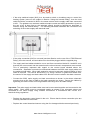
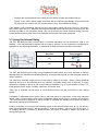
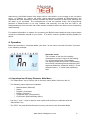
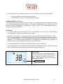
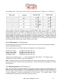
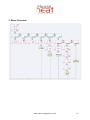
HouseHeat
FHT 8W BoilerConnect
Installation and User Guide
Product Code HH45240
Please read these instructions carefully before installation and operation and keep
them for future reference
www.house-intelligence.co.uk
First UK Edition, November 2008, Documentation © 2008 HouseTech-Solutions Ltd.
All rights reserved. This document may not be reproduced or copied whole or in part in any form or
duplicated or processed by electronic, mechanical or chemical means without prior permission. It is possible
that this document contains technical or printing errors. The information in this document is nonetheless
regularly checked and corrections made in subsequent editions. No liability is accepted for technical or
printing errors or their consequences. All trademarks and patents are acknowledged. Modifications owing to
technical improvements may be made without prior notification. Printed in Hong Kong.
45666 Y2008 V1.0
www.house-intelligence.co.uk
2
1. Description and Function .............................................................................. 4
2. Safety Information......................................................................................... 5
3. Installation..................................................................................................... 5
3.1 Selecting a Location...................................................................................................5
3.2 Mounting and Installation ...........................................................................................5
3.3 Using the Internal Relay.............................................................................................8
4. Operation ...................................................................................................... 9
4.1 Operational and Display Elements; Main Menu .........................................................9
4.2 Manual Mode (“Manuell”) .........................................................................................10
4.3 Status.......................................................................................................................10
4.4 Register (“Anlernen”)................................................................................................11
4.5. Delete (“Löschen”) ..................................................................................................11
4.6 Threshold value (“Grenzwerte”) ...............................................................................11
4.7 FS20 Menu (External Relay)....................................................................................12
4.7.1. Activation (“Aktivieren”)................................................................................................ 12
4.7.2. FS20 Addresses (“FS20-Adresse”).............................................................................. 13
4.7.3 FS20 Registration (“FS20 Anlernen”)............................................................................ 13
5. Additional Information ................................................................................. 14
5.1. Transmission Range ...............................................................................................14
5.2 FS20 Repeater Module ............................................................................................14
6. Technical Data ............................................................................................ 14
7. Menu Overview ........................................................................................... 15
8. System Overview........................................................................................ 16
www.house-intelligence.co.uk
3
1. Description and Function
Many heating systems including the circulation pump operate continuously regardless of the actual
heating demand of the building and are therefore energy-inefficient. If a HouseHeat system is
installed comprising of Wireless Room/Zone Thermostats and Wireless Valve Motors, the addition
of a FHT 8W BoilerConnect unit can boost the energy efficiency of the system still further by
offering a solution to the problem of the boiler and pump operating continuously. BoilerConnect
evaluates the data transmitted wirelessly between the room thermostats and the valve motors for
up to ten rooms/zones and is able to regulate the heating output of the boiler to precisely match the
actual heating demand of the building, increasing the energy efficiency of the heating installation.
The switched output of BoilerConnect may be either connected to the burner control of the boiler
and/or the circulation pump.
In automatic mode, BoilerConnect compares the transmitted data from the Room Thermostats
(percentage opening of radiator valves) to a freely programmable threshold value on a minute-byminute basis and switches its output relay on or off correspondingly. Manual switching by the user
is also possible.
BoilerConnect is able to monitor wireless data communication between the FHT 80B Room
Thermostats and FHZ 1000 HouseMaster (if installed) and FHT 8V Motor Valves i.e. all HouseHeat
system components.
BoilerConnect is able to recognise if wireless signal reception is lost for whatever reason and
depending on the specific configuration, intelligently switches into safe mode.
Integration of BoilerConnect with a HouseHeat system is achieved by simple registration of the
HouseHeat Wireless Room Thermostats installed in the system.
The display of the device shows both the status of each room thermostat (e.g. reception failure) as
well as the switched output of BoilerConnect and other useful operational information.
The IP-65 housing allows BoilerConnect to be fitted in a damp environment.
The system operates in the highly secure 868 MHz frequency band.
An overview of how BoilerConnect integrates with other HouseHeat system components is
illustrated by the following schematic:
www.house-intelligence.co.uk
4
2. Safety Information
Connection of the device to the 230 Volt mains electrical supply should be carried out by a
qualified professional electrician in accordance with current U.K. regulations.
Connection of the device to the heating system should similarly be carried out by a qualified
professional heating installer in accordance with current U.K. regulations.
3. Installation
3.1 Selecting a Location
The IP 65 housing allows the device to be installed in dry or damp areas.
The chosen location should be chosen so that reliable wireless signal reception is assured from all
HouseHeat Room Thermostats and also HouseHeat FHZ 1000 HouseMaster (if fitted). If any
doubt exists about the reliability of signal reception in the chosen location, this should be tested
before final mounting of BoilerConnect.
3.2 Mounting and Installation
The device should be mounted e.g. on a wall using screws.
− Remove the cover of the housing by removing the four face-plate screws
− Mark 4 mounting holes on the surface on which the unit is to be mounted through the four
holes of the casing (see picture on the next page)
− Drill holes in the surface/wall and insert anchors/rawlplugs
− Mount the unit using screws inserted through the four screw holes into the holes in the wall.
The cable unions must face downwards.
− Unscrew and remove the four plastic screws on the front panel (see picture on the next
page).
− Unscrew and remove the four plastic hexagonal bolts (see photo next page) and carefully lift
out the electronic control board
− Loosen the cable unions on the underside of the device and insert the 230V mains supply
cable (maximum diameter 10 mm) through the left cable union
− Strip approximately 6mm of insulation from the 230V supply cable and fasten securely in the
corresponding screw clamps of KL1 (AC power in) (see picture next page)
www.house-intelligence.co.uk
5
1. Four plastic screws
2. Four mounting screw holes
3. Cable unions
1. Four hexagonal plastic bolts
1. KL1: Connection to 230V mains supply
2. KL2: Electrical load connection (relay
switched output)
www.house-intelligence.co.uk
6
− If the relay switched output (KL2) is to be used to switch a circulation pump or control the
heating system (more on this subject in Section “Using the Internal Relay”), then the load
cable should be connected to KL2 in the same manner as the supply cable was connected
to KL1. The guidance on maximum switched output current and safety precautions (such as
the use of an 8 Amp fuse on the switched output) should be followed as described in
Section “Using the Internal Relay”. The following schematic illustrates the connection and
switching of the mains supply and electrical load:
− If the relay connection (KL2) is not used (see later Section on the use of the “FS20 External
Relay”) then the second, unused cable union should be plugged with the supplied plug.
− The supply and load cables should be run to and from connection blocks KL1 and KL2 such
that they do not encroach into the area where the other electronic components are mounted.
This is particularly important with regard to the control board situated above the
connections. Separation must also be maintained between the 230V main supply cable and
the switched load cable. When safe separation cannot be assured, double isolation of each
cable is required. This can be achieved e.g. by using a silicone or glass-fibre sheath over
the section of the supply and load cables from which the outer insulation has been removed
− Connect the 230V mains supply and load connections as shown in the above schematic
ensuring that an 8A fuse is fitted to the load connection as shown. Secure the cables by
tightening the cable unions and using suitable wall fixings such as cable clamps.
Important: The main supply and load cables must not be connected together and connected to the
mains supply. Both cables must be connected exactly as shown in the schematic above and
connected to the mains supply using suitable connections in accordance with current U.K.
electrical wiring regulations.
− Replace the electronic control board in the unit. Ensure that the three connection pins are
correctly inserted into the socket.
− Replace the control board and secure using the four hexagonal bolts removed previously
www.house-intelligence.co.uk
7
− Replace the face plate and secure with the four plastic screws removed previously
− Switch on the 230V mains supply and check that the liquid-crystal display is functional (first
all segments are visible, then the product version, then the operational display)
If the display is not operational, disconnect the mains supply (switch off at the fuse box / consumer
unit), and re-open the unit. Remove the control board and check that the three connection pins are
correctly inserted in the connection block. Do not re-connect the mains electrical supply until the
control board and face plate have been replaced and screws have been tightened!
3.3 Using the Internal Relay
The FHT 8W BoilerConnect internal relay is switched depending on the demand for heat in the
building. If no heat demand is present then the relay is inactive i.e. the contacts are configured as
displayed in the following schematic. If a demand for heat is sensed, the relay is activated:
Demand
Relay position
Off
On
The FHT 8W BoilerConnect relay has gold-plated contacts which are more resistant to foreign
deposits and also facilitate the reliable switching over extended periods of small voltages typical of
control systems.
The maximum switched output current of the relay is limited to 8 Amps. When a mains-powered
electrical device is to be switched (such as a boiler), a suitable safety fuse is required. In many
cases this is already in place as part of the heating installation (e.g. a circuit breaker or fuse). For
loads greater than 8 Amps a suitably rated fuse should be used.
There are in principle several ways in which BoilerConnect can be connected to the heating
system.
If available, a dedicated boiler control input is the best option for connection of the relay switched
output. Many modern boilers offer freely configurable inputs which may be used for this purpose.
The input should be configured so that the boiler is switched into standby mode when no heating
demand is sensed by BoilerConnect.
Another possibility is to connect the switched output of the BoilerConnect relay to e.g. the boiler's
room thermostat/timer control. Almost all boilers - even old models - have an input of this type. If
no heating demand is sensed by BoilerConnect, this input is utilised to switch the boiler into
energy-saving mode.
www.house-intelligence.co.uk
8
Alternatively, the BoilerConnect relay output can be connected in to the supply to the circulation
pump. In isolation (i.e. without the boiler ignition also being switched by BoilerConnect) this
represents the least satisfactory solution because the boiler continues to heat water although the
hot water is not circulated. The consequences of this are two-fold: firstly, the energy-saving
potential of BoilerConnect is not fully realised; and secondly, the fact that the heat is not
transported away from the boiler can under certain conditions lead to the boiler control temporarily
malfunctioning.
For detailed information on options for connecting the BoilerConnect switched relay output please
consult the installation manual for your boiler. If in doubt, consult a qualified heating installer for
advice.
4. Operation
BoilerConnect starts in “Automatic Mode“ (see item 1 on the menu overview in Section 7) as seen
in the following example:
Automatic mode:
The numbers on the top of the display
correspond to rooms or zones in the building
(i.e. to HouseHeat Room Thermostats).
The display shows which Room Thermostat(s)
are currently requesting heat by displaying two
segments below the respective zone(s). In this
example zones 1, 3, 4 and 8 are requesting
heat.
4.1 Operational and Display Elements; Main Menu
− The ”Menu/Enter” key is used to call up the main menu (Menu Overview, item 2)
− The following menu options are available:
o
o
o
o
o
o
Manual Mode (“Manuell”)
Status
Register (“Anlernen”)
Delete (“Löschen”)
Threshold value (“Grenzwerte”)
FS20 menu (External-Relay option)
− Use the “+” and “-“ keys to select a menu option and confirm your selection with the
“Menu/Enter” key.
− The “ESC” key returns BoilerConnect from any sub-menu to the Automatic Mode.
www.house-intelligence.co.uk
9
− The switching status of the BoilerConnect relay is indicated by means of the green LED:
o
o
LED illuminated: ON (heating demand sensed)
LED extinguished: OFF (no heating demand sensed)
4.2 Manual Mode (“Manuell”)
In this operating mode (see Menu Overview, item 3), the heating demand transmitted wirelessly
from the HouseHeat thermostats is ignored. In this mode, the BoilerConnect relay (and hence the
heating system) is switched on or off with the “+” and “-“ keys. In this mode, BoilerConnect is
acting as a simple on/off switch.
4.3 Status
− This menu option (see Menu Overview, item 4) enables the current status of each Room
Thermostat to be viewed in the BoilerConnect display.
− Each Room Thermostat (i.e. each room/zone) can be selected individually using the “+’ and “-“
keys. The bar along the top of the display (see Section 4. Above) indicates which room/zone is
currently being displayed. The current radiator-valve opening commanded for that room/zone is
displayed. For unused memory locations (no corresponding HouseHeat zone registered to
BoilerConnect), bars are displayed instead of a percentage value.
− If no wireless signal is received for a particular zone then “EA” is displayed
− If the valve opening of the radiators in the room/zone is sufficient to trigger a demand for heat
then a corresponding symbol appears in the bottom right of the display:
Status mode:
In this example Room Thermostat number 4
(i.e. room/zone 4) has radiator valves open to
38% of maximum (“maximum” means “fully
open”). This results in a demand for heat which
is indicated as shown:
Demand for heat
www.house-intelligence.co.uk
10
4.4 Register (“Anlernen”)
If this menu option is selected (see Menu Overview, Item 5), BoilerConnect waits for a request
from a Room Thermostat in order to register the corresponding room/zone to BoilerConnect (up to
ten zones may be registered). The special function “CoDE” of the Room Thermostat (or FHZ 1000
HouseMaster) is used to send this request to BoilerConnect. Please review the HouseHeat User
Guide to learn how to use the “CoDE” special function (or for the FHZ 1000 HouseMaster, please
consult the HouseMaster User Guide).
− If BoilerConnect receives such a request, the Room Thermostat making the request is saved to
the next free memory location (memory locations are numbered 1 to 10). The “address” of the
Room Thermostat is shown in the display and the memory location assigned to the Room
Thermostat is shown in the top line of the BoilerConnect display
− If all memory locations are already occupied, the error message “E1” is displayed and no more
Room Thermostats maybe registered.
− The error message “E2” indicates that the Room Thermostat has already been registered to
BoilerConnect
4.5. Delete (“Löschen”)
− If a Room Thermostat is required to be deleted (i.e. “de-registered”) from the memory of
BoilerConnect, the Room Thermostat should be selected using the “+” and “-“ keys and
confirmed with the “Menu/Enter” key (see Menu Overview, item 6). The address of the Room
Thermostat is displayed next to the memory location.
− On deletion, the display shows: “Der Regler wird gelöscht” (“the thermostat has been deleted”)
− After deletion the associated memory location is available for registration of another Room
Thermostat should this be required.
4.6 Threshold Value (“Grenzwerte”)
The threshold value specifies how much a radiator valve needs to be open in a given zone
(expressed as a percentage of fully open) before a demand for heat is deemed to be present. If
the valve opening is the same or greater than this value, a heating demand is considered to exist.
The threshold value is set in the factory at 1%. It may be appropriate to increase this value, for
example, if a valve in a particular zone has the characteristic that it only permits significant flow
with greater percentage openings.
− First, the zone (Room Thermostat) for which the threshold value is required to be adjusted is
selected using the “+” and “-“ keys (See Menu Overview, item 7)
− Confirm your selection with the “Menu/Enter” key. The current threshold value for that zone is
displayed and can be modified using the “+” and “-“ keys (Menu Overview, item 8)
− Save the new threshold value with the “Menu/Enter” key
− The display shows: “Speichern des neuen Grenzwertes” (“Save new threshold value”)
www.house-intelligence.co.uk
11
4.7 FS20 Menu (External Relay)
Use of the BoilerConnect internal relay as described above in Sections 3.2 and 3.3 is strongly
recommended. However, if it is impossible to site BoilerConnect sufficiently close to the boiler to
enable a wired connection to be made, it may be possible to utilise an FS20 “radio bridge” to
switch the boiler remotely. Please contact HouseTech for further information if this solution is
necessary.
The FS20 menu (see Menu Overview, item 9) is only required if an external FS20 “bridge” wireless
relay is being used. If this is not the case, this section (4.7) may be disregarded.
The following schematic illustrates the use of FHT 8W BoilerConnect together with an FS20
external relay to switch the boiler remotely:
4.7.1. Activation (“Aktivieren”)
This menu option (Menu Overview, item 10) allows the behaviour of the BoilerConnect wireless
transmitter output to the FS20 external relay to be specified:
Setting “0”:
Wireless transmission to the FS20 external relay is not required. (This is the default
setting which should be used when no external FS20 relay is being used, which is
normally the case)
Setting “1”:
The external FS20 relay switch is activated when a heating demand is sensed
Setting “2”:
The external FS20 relay switch is activated when no heating demand is sensed
If modified, the new setting should be saved with the “Menu/Enter” key. The display shows:
“Speichern der Einstellungen” (“Save new setting”)
www.house-intelligence.co.uk
12
(In the table below, “menu point” means “setting” as described here i.e. Setting = 1 or Setting = 2)
These options allow the behaviour of the wireless-bridge relay to be defined if wireless
communication should fail between BoilerConnect and the FS20 external relay. If wireless
communication fails for any reason, the FS20 relay opens at the latest 15 minutes after the last
wireless signal was received. It is thus possible by means of this setting to define whether the
output defaults to “heating demand is present” or “heating demand is not present” if wireless
communication should fail between BoilerConnect and the external relay. In other words, it is
possible to specify whether you wish the boiler to be switched on or off if wireless communication
should fail between BoilerConnect and the FS20 remote relay.
4.7.2. FS20 Address (“FS20-Adresse”)
(The following information should be read in conjunction with the User Guide supplied separately
with the FS20 wireless relay.)
The constituent parts of the FS20 address are displayed in the following order:
House code 1 (HC1)
House code 2 (HC2)
Address Group (AG)
Sub-address (UA)
(see
(see
(see
(see
Menu Overview, item 11)
Menu Overview, item 12)
Menu Overview, item 13)
Menu Overview, item 14)
These can be changed using „+” / „-” and confirmed using “Menu/Enter“. The display shows:
“Speichern der neuen Adresse” (“Save new address”).
Note: The address group ‘44’ and the sub-address ‘44’ have a special meaning. When these are
set, the unit acts as a “master’ device/“function group”. Further information is available in the FS20
documentation.
4.7.3 FS20 Registration (“FS20 Anlernen”)
Next, the FS20 relay should be switched to programming mode in order that communication with
BoilerConnect may be configured. This is described in the documentation for the FS20 relay. If
the menu option “FS20 Anlernen” is then selected, BoilerConnect transmits a signal and the FS20
is then configured to receive communication on this channel. The display shows: “FS20
Anlernbefehl wird gesendet” (“FS20 training command sent”).
www.house-intelligence.co.uk
13
5. Additional Information
5.1. Transmission Range
The FS20 external relay system operates in the 868-MHz frequency band which is also used by
other wireless devices. It is therefore possible that a reduction in operational range or disruption to
the operation of this device may occur as a result of other devices transmitting on the same or
neighbouring frequencies.
The nominal range of 100 metres is a ‘free-field’ range. This is the range under ideal conditions
with no obstacles between transmitter and receiver. In practice, walls, ceilings etc. will often exist
between transmitter and receiver which in turn will reduce the operational range.
Other causes of reduced wireless transmission range may include:
− High-frequency disturbances of all kinds
− Buildings and structures of any kind
− Conducting objects in or near to the line of transmission which can lead to distortions and
reductions of the electromagnetic field
− The distance of the transmitter or receiver to conducting surfaces or objects (including the
human body and the ground) influences the transmission characteristics of the antennae and
consequently also the range
− Broad-band disturbances in urban areas can reach peaks which reduce the signal-to-noise ratio
and reduce the range
− Poorly shielded computer equipment can irradiate the receiver and reduce the range
5.2 FS20 Repeater Module
If it is necessary to increase the range to ensure reliable wireless communication, a ‘repeater
module’ may be purchased as part of the FS20 system described in Section 4.7.
6. Technical Data
Electrical supply voltage.....................................................................................230 V, 50 Hz, 10 mA
Switched relay output: ...........................................................................................1 x um, 230 V, 8 A
Number of room thermostats..................................................................................................Max. 10
Operating frequency: .......................................................................................................868.35 MHz
Device Housing:……………………………………....................................................................... IP 65
Dimensions:…………………................................................................................... 115 x 90 x 55 mm
www.house-intelligence.co.uk
14
7. Menu Overview
www.house-intelligence.co.uk
15
8. System Overview
www.house-intelligence.co.uk
16