1
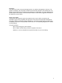
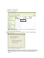
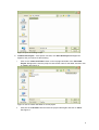
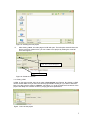
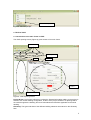
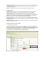
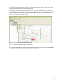
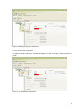
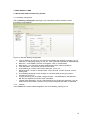
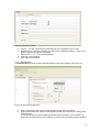
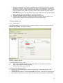
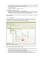
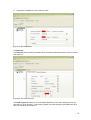
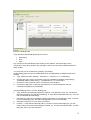
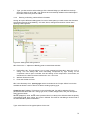
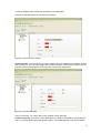
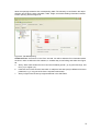
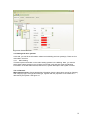
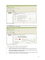
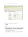
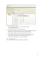
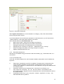
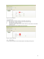
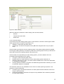
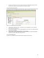
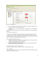
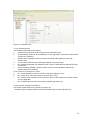
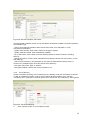
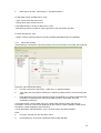
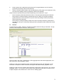
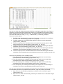
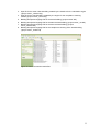
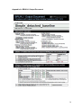
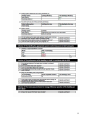
18/06/09
User
Guide
cSAP
Consultation software for Part L
2010. Implementing SAP2009
methodology
Part of the National Calculation Methodology
A User Guide to cSAP
(cSAP 1.0.0)
18 June 2009
1
Disclaimer
The cSAP User Guide cannot provide legal advice or a definitive interpretation of the law. The
guidance provided in this document is limited to the technical operation of the software tool. It is
offered in good faith but is not binding on any person(s) or organization. The same applies to the
default values in the interface, which should be viewed as conservative suggestions intended to
be replaced by actual values.
Scope of the guide
The purpose of this guide is to give an introduction to the use of cSAP, an interface and
calculation engine for the proposed new approach to the Government's Standard Assessment
Procedure (SAP) for the Energy Rating of Dwellings. It has been created solely to enable users
to feedback comments on the proposed revisions to Part L of the Building Regulations in relation
to new dwellings.
This guide includes:
·
How to work through the cSAP software
·
How to obtain the SAP rating, and 2010 compliance document
·
Guidance on how to assemble the required information for your own building
2
1. cSAP basics – Getting started
1.1. Opening cSAP, see Figure 1:
Double-click to
start cSAP
Figure 1: How to open cSAP
1.2. Creating new/opening existing projects
After you double click cSAP.exe, a new window appears, which gives two “cSAP Start-up
Options”, see Figure 2:
Figure 2: cSAP Start-up dialogue box
a. Select an Existing Project to open – Selecting this option and clicking on “OK” opens the
“Open File” dialogue box, allowing you to browse through your network/computer to locate a
project. You can also use the “open file” icon to browse if you have passed this start-up
options box.
3
Figure 3: Open an Existing Project
b. Create a New Project – If this option is chosen, the “Save New Project” dialogue box
appears, and you need to do the following:
i.
Click on the “Create new folder” button on the top right hand side of the “Save New
Project” dialogue box, enter the project’s name as the name for the folder, and then click
on “Open” (see Figure 4).
Figure 4: How to create new folder for a new project
ii.
Click into the “File Name” field and enter the project name again and click on “Save”.
See Figure 5.
4
Figure 5: Creating the new project
iii.
After clicking “save”, the main page of cSAP will open. The left option area will show the
project you have created. Also, you can create a new project by clicking the “new file”
icon. See Figure 6 :
Click ‘new’ to create a new project.
Newly created project
name
Figure 6: Create the new file
1.3. Closing cSAP
In ‘File’ on the main tool bar, there is an option ‘Close project’ see Figure 8. By clicking it, cSAP
can be closed. Make sure you save the current project before closing it, if you want to retrieve it
later. You also have the option to ‘Save as’, see Figure 7, in order to retain the first version of the
project and adapt it to a further version by varying just some parameters.
Figure 7: save as the project
5
Click to close the project
Figure 8: Close the project
2. TOUR of cSAP
2.1 Introduction to the main forms in cSAP
The cSAP opening screen (Figure 9) gives access to four main forms:
Main Forms
Viewing Filter
Tab
Sub- tabs
Data entry
Window
Object selection tree
Figure 9: cSAP Opening screen
Project & Site: The Project & Site form is where the General information relating to the project is
entered, such as the dwelling configuration, location of the project, definition of openings which
are used throughout the dwelling and some miscellaneous information applicable to the whole
dwelling.
Geometry: The types and sizes of the different building elements are entered on the Geometry
form.
6
Heating & Other systems: The heating & other systems form is where all the building’s systems
are described, including main heating, water heating and ventilation. It is also used to enter
renewable energy systems.
Results: The Results form is used to carry out and display the DER and SAP rating.
2.2 Viewing Filters
All objects: When this option is chosen, all the entered details (“objects”) of the project are
visible in the object tree section. This function applies to all the forms except ‘Results”.
Component trees: When this option is selected, only the objects relevant to the particular
chosen form will be visible in the object tree section. This function applies to all the forms except
“Results”. You are advised to use this viewing filter when inputting data for the first time for a
particular dwelling, and to use the “All objects” view when editing data later.
Renewable Component: this option is only visible under the form “Heating & Other systems”.
By clicking this option, all the renewable components within the project will be shown in the object
tree display section.
Operations: this option is only visible when under the form “Results”. It is automatically chosen
under the “Results” form in cSAP.
2.3 Basic operational functions in cSAP
2.3.1 Adding project components
To add the components to the project, choose the “all objects” viewing filter, and right click the
project name in the objects tree display area. Then a window with all the available options within
the whole project will pop up, (see Figure 10). Left click the element you would like to add, and a
new component will be added and listed in the corresponding category. If you create an
unwanted component, use delete at the foot of the pop up window.
Compulsory information
Figure 10: Adding project components
7
NB: RED highlighted areas are compulsory information that must be filled in, otherwise an error
will result when attempting to produce a SAP result.
After changing the viewing filter to “component tree”, right click the project name in the objects
tree display area. A window with available options within the chosen form will pop up, in this case
the form” Project & Site”. See figure 11. By left clicking the element you wish to add into the
model, a new component will be created.
Figure 11: How to add the new building elements
2.3.2
To copy or delete the project components
Left click the component you wish to copy or delete, right click the mouse, then left click “delete”
or “copy” as appropriate from the option window. See figure 12.
8
Figure 12: Deleting the project components
2.3.3 To rename the components
To rename a project component, right click the element you wish to rename. Left click “rename” in
the option window that pops up; see Figure 13. Type in the new name and press “enter” to
confirm.
Figure 13: To rename the components
9
3. DATA ENTRY in cSAP
3.1 General tab within the data entry window
3.1.1 Dwelling configuration
Sub tab Dwelling configuration (see Figure 14) is the place to select the basic overall
information for the dwelling.
Figure 14: Sub tab dwelling configuration
a. Type of dwelling- At this point, you should enter whether the dwelling is existing, new, an
extension or undergoing change of use, etc. SAP is primarily intended for new dwellings.
b. Built form – is the dwelling a house, a bungalow, a flat, or a maisonette?
c. Detachment – how the house is attached/detached to/from adjoining dwellings.
d. Front orientation - the direction the house front faces.
e. Is the dwelling in a smoke control area? Unknown, yes or no?
f. Electricity tariff – Choice of: standard tariff; 7-hour off-peak; 10-hour off-peak; 24-hour
heating tariff
g. Is the dwelling designed to meet a target of <125 litres water per day per person?
Choose from yes or no.
h. Living area (living room or largest contiguous space – see SAP2009 for full definition).
NB: this is a required input for the cSAP calculation.
i. Thermal mass parameter: This is a characteristic of the construction elements. It can be
obtained from the Indicative values in the thermal mass parameter table 1C SAP2009.
3.1.2 Location
The Location tab contains data that applies to the whole dwelling. See Figure 15
10
Figure 15: Sub tab Location
a. Country – Location of the dwelling (to determine which regulations are in force).
b. Weather region - (pick the closest to your site from the available locations – there are 13
different regions for England and Wales).
c. Address line 1, 2, 3 – of the dwelling location.
d. Post town for the dwelling.
e. Post code of the dwelling
3.1.3 Miscellaneous
The Miscellaneous sub tab contains data that applies to the whole dwelling. See Figure 16
Figure 16: Sub tab Miscellaneous
a.
b.
Date of assessment. NB: This is a required input for the cSAP calculation.
Lighting: Enter either the number of fixed lighting outlets and number of low energy fixed
lighting outlets.
Or, the percentage (%) of fixed lighting outlets that are low energy. (The calculation of
lighting use is partly based on the proportion of fixed low energy lighting outlets installed.)
11
c.
d.
e.
Windows configuration: choose the overshading type for all the windows from “very little”,
“average or unknown”, “more than average” and “heavy”. Overshading for all windows, ie
the proportion of the sky that is blocked by other obstructions or buildings. (The ‘average’
category applies in many cases, and can be used for SAP calculations if the shading is
not known)
For “How window open in the hot weather” select from “trickle vent only”, “window slightly
open”, “window open half of the time” and “window fully open”.
Choose if the dwelling had assessed for zero carbon home or not.
Additional allowable electricity generation applicable to dwelling. NB: this option is only
visible when the dwelling is being assessed for the Zero-Carbon Home.
3.2 Project & Site form
3.2.1
Opening type
The Opening type tab is the place to enter information related to groups of windows and doors
throughout the dwelling; see Figure 17 below.
Figure 17: Opening type tab
In general properties section, enter:
a.
Data Source: choose from “BFRC table”, “SAP table” or “manufacturer declaration”
b.
Type: choose between window and door
2
c.
U-value: fill in the U-value in W/m K
In glazing properties section, enter:
a. Glazing type: choose from single, double or triple glazing, or “secondary glazing”, with
coating options
b. Glazing Gap: this option is not relevant/available when “single” is chosen in the glazing type.
c. Argon Filled: choose if there is argon gas in a sealed glazing unit between the glass panes.
12
d.
e.
f.
Total solar energy transmittance: the total solar energy transmittance factor of the glazing at
normal incidence, see SAP Table 6b for more information.
Light transmittance: similar factor used in calculation of lighting requirement, see SAP Table
6b for more information
Description: available for user to add any notes.
In frame properties section, there are:
a. Frame type: choose from “wood” “PVC” and “metal” series
b. Proportion of opening that is glazed – to allow software to determine the part that is solid or
frame. NB: Enter proportion as a factor, not a percentage. This option is only visible while
choosing “window” or “roof window” in the type, general properties section.
You are advised to rename each “opening type” so that it is readily recognisable in the drop-down
option menus later.
3.2.2
Special features
The special features tab provides a method to allow for the benefits of new energy-saving
technologies that are not included in the published SAP 2009 specification currently being
consulted on. To add a special feature in the Building see figure 18:
Figure 18: Adding a special feature
In general, a technology may use one form of energy to achieve savings in another form of
energy. Figure 19 shows how it is defined in cSAP.
a.
b.
c.
d.
Energy saved or generated: the amount of energy saved by the technology applied in the
building in kWh/year, refer to SAP2009 for further details
Code of fuel saved or generated: the code of the fuel that is saved by the application of the
technology, see the SAP 2009 table 12 for more information.
Energy used: the amount of energy used by the technology in kWh/year
Code of fuel used: the code of the fuel that the technology uses, see SAP 2009 table 12.
13
e.
Description: available for user to add any notes.
Figure 19: Special features
3.3 Geometry
The Geometry form is where information about the building elements and their areas is entered.
See figure 20
Figure 20: The Geometry form
The Building part tab allows you to enter details separately for the main dwelling and for any
extensions or a conservatory, and to specify globally the thermal bridging associated with each
part of the dwelling. See Figure 21.
14
Figure 21: Building parts
Three sub-tabs under Building parts give access to
•
•
•
Roof/ceiling
Wall
Floor
Any of these can be replicated by right-clicking on the element, then left clicking on the
component in the pop-up window. Any openings in wall or roof can also be defined within this
same window.
3.3.1 Summary of how to define the geometry of a building
Create building parts: set up the building parts which are appropriate for different parts of the
dwelling.
a. Type: select from main “dwelling”, “extension 1”, “extension 2” or “conservatory”
b. Conservatory type: select conservatory type from “separated unheated cons(ervatory).”
“Separated heated cons(ervatory)”; “not separated” or “no conservatory”
c. Construction year: Enter the year of construction of the dwelling.
d. Construction age band: choose the age band from A- K that corresponds with the
constructions employed in the dwelling.
In thermal bridging section, for each building part:
e. Type: select the thermal bridge type from” default”; “user defined y value” (i.e. the same for
all thermal bridges in this part of the dwelling), or “user defined individual value” (i.e. for more
than one different thermal bridge)
f.
User defined y value: this information needs to be entered if “user defined y value” is chosen
in the thermal bridge type. See SAP 2009 Appendix K for more information.
g. Calculation reference: for your notes or reference.
h. Location: if “user defined individual value” is chosen in the thermal bridge type, you will
need to select where the thermal bridge is located, e.g. “junction with external wall”, “junction
with party wall” or “junction with floor”
15
i.
Type: you also need to select what type of the thermal bridge you will add from the drop
down list, and then click “add”. You will then have successfully added one thermal bridge in
the model; others may then be added.
3.3.2
Entering roof/ceiling, wall and floor information
Having set up the different building parts, for each of those parts you need to enter the elements
surrounding that part of the dwelling – the walls, floors, ceiling/roof and which of them have
openings. See Figure 22:
Figure 22: Adding Roof-ceiling element
NB: Click on the “+” adjacent to Building parts to reveal three sub tabs
a.
b.
c.
Roof/ceiling tab: This tab allows you to enter geometrical information about the roof or
ceiling. You can always add more roof/ceiling components by right clicking on the
component name to open a window, then left clicking on the component in that window, as
described in the basic functions instructions in 2.4.1 and 2.4.2
Wall tab: Similar for walls
Floor tab: Similar for floors
NB: In the Geometry form, ‘opening type’ which is included in the “Project & Site” form is also
available to allow the user to add to or edit the existing opening-type.
Create the roof / ceiling: This is done in the roof/ceiling tab. You will be asked to fill in the
parameters that define the roof / ceiling; type, area, U-value, Kappa value, and your description.
See Figure 23 below.
NB: Кm (Kappa m) value, the Кm value (renamed from Cm value) is the effective thermal capacity
of an element (wall, floor, ceiling, etc), given in kJ/m2K. The rules for calculating it can be found in
the CEN standard: prEN 13790:2006.
Type: select from list of the typical options for the roof.
16
U value and Kappa value: obtain this information from SAP tables.
Description: Add description to roof/ceiling if necessary
Figure 23: Create the roof / ceiling
Create the walls: In the “Wall” tab, you will be asked to fill in the parameters that define the wall;
type, construction, area, U-value, Kappa value, and a description. See Figure 24 below. Choose
from the list of the typical options for the type and construction respectively.
Figure 24: Creating the walls
Then for each wall, you need to specify any window or door openings.
Create the opening: this is done in the “Wall opening” sub-tab. It is created by right clicking the
wall icon and then selecting the wall opening option. You will be asked to enter the information
17
about the openings related to their corresponding walls. The hierarchy is confirmed in the object
selection tree. Enter the type, orientation, width, height, and further shading information relevant
to each opening. See the Figure 25.
Figure 25: Tab Wall Opening
Create the Floor: this is done in the “Floor” sub-tab. You will be asked to fill in information about
the floor in order to define the floor element, in a similar way to roof/ceiling and walls. See Figure
26.
a.
Storey: Enter here whether the floor concerned is below ground (-1), at ground level (0), first
floor (+1) or higher (+2).
b.
Heat loss area: Enter here the area which is subject to heat loss (may be different from area
parameter, e.g. if only part of the floor is exposed underneath)
c.
Storey height: Enter the storey height as defined in the SAP 2009
18
Figure 26: Create the Floor
3.4 Heating and other systems
In this tab, you can fill the information related to the building services system(s). There are four
main tabs in this form.
3.4.1 Main Heating
This tab requires information on the main heating systems in the building. Here, you need to
select each heating system in turn (if there is more than one) and then enter the following
information on the sub-tabs General, Data source, System description and System controls.
Sub tab General:
Main Heating system: Choose appropriate information from the drop-down menus for Category,
Sub-category, Type, Sub-type and Fuel type, together with the proportion of the heat that is
delivered by this system. See figure 27
19
Figure 27: General tab
Sub-tab Data source: In here, you need to select the data source, either from “SAP table” or
“manufacturer declaration” See Figure 28
Figure 28: Sub-tab Data source
If “declared value” has been selected, you will be asked to fill in:
a.
Heating efficiency: efficiency of the heat generator in %
b.
Appliance HETAS approved: state if the appliance has been HETAS approved or not.
c.
Passive flue gas heat recovery system: choose yes if there is a passive flue gas heat
recovery system applied to this heat generator.
d.
PFGHRD index: provide the index if a passive flue gas heat recovery system is in place.
e.
Boiler index number, obtain from the relative manufacturer.
20
f.
Boiler make and model, obtain from the relative manufacturer.
g.
BS test method.
Sub tab System description: In here, you need to provide more information about the main
heating system. See Figure 29
Figure 29: sub tab system description
a.
Heat emitter: choose from radiator, floor or both.
b.
Underfloor heat emitter type: If there is underfloor heating, what type of floor is it embedded
in?
c.
Condensing boiler: choose if there is condensing boiler or not.
d.
Gas or oil boiler type: if the boiler is gas or oil fuelled, choose the boiler type from the drop
down menu.
e.
Combi boiler type: if there is a combi boiler choose type from the drop down menu.
f.
Solid fuel boiler type: choose from “ independent” (boiler), “open fire” or “closed room
heater”
g.
Case heat emission at full load. If “range cooker” is chosen as boiler type, enter this value
based on the approved calculation in the SAP 2009 appendix D5.
h.
Heat transfer to water at full load. If “range cooker” is chosen as boiler type, enter this
value.
i.
Heating flue type: choose from “ open flue”, “ balanced flue” and “ chimney”
j.
Heating flue fan: select if it is fan assisted or not
k.
Central heating pump in heat space – confirm or note that it is not in the heated space
l.
Oil pump in heated space – confirm or note that it is not in the heated space
21
Sub-tab System controls: This section requires information about the heating controls. See
figure 30.
Figure 30: System controls sub tab
Control type: Select from drop-down menu for this heating system
Then in “System features” box:
a.
Boiler interlock: choose yes if there is boiler interlock.
b.
Delayed start thermostat: select if the chosen starting time for space heating is delayed
depending on the temperature measured inside or outside the dwelling.
c.
Boiler fuel feed: if solid fuel, choose feed method from drop down menu
d.
Compensation: Select appropriately if the boiler flow temperature is modulated
(“compensated”) depending on load or weather (outside temperature)
e.
Burner control: choose between “ on/off” and “ modulating”
3.4.2 Secondary heating
If there is secondary heating added into this building. See Figure 31:
22
Figure 31: Secondary heating tab
Within System information box, enter information on Category, Code, Fuel code and Data
source using drop down menus.
If you have selected “from manufacturer declaration” as the Data source, you will need to fill in
- Heating efficiency: enter heat system efficiency as a factor
and to provide data in the “Declared values” box:
a.
Boiler index number - obtain from the relative manufacturer.
b.
Boiler make and model obtain from the relative manufacturer.
c.
Heating BS test method. See SAP 2009 for more information.
d.
Heating flue type: choose from “open flue”, “ balanced flue” and “ chimney”
e.
Heater air change rate (ACR) in air change rate per hour (ACH)
f.
Appliance HETAS approved or not
3.4.3 Renewable Component
Use this tab if renewable energy sources are used at the dwelling, e.g., Photovoltaic cells, or a
wind turbine.
3.4.3.1 Photovoltaic cells
In this tab, you will be asked to fill in the information related to photovoltaic cells if installed, see
Figure 32:
a.
b.
c.
d.
Peak power: (compulsory input if PV is installed). The peak power corresponds to the
rate of electricity generation in bright sunlight, formally defined as the output of the
module under radiation of 1 kW/m² at 25°C; it also depends on the type of module as well
as its effective area.
Orientation: Select from the drop-down list: S, SE, SW, E, W, NE, NW, or N.
Pitch: select from “horizontal”, “30”, “45”, “60” and “vertical”. The inclination of the
photovoltaic panels in degrees from the horizontal where 0 is a horizontal surface and 90
is a vertical surface.
Overshading: select from “none or very little”, “modest”, “significant” or “heavy” – see
SAP 2009 table H4 for guidance.
23
Figure 32: Photovoltaic tab
3.4.3.2 Wind turbine
If applicable, enter the information related to a wind turbine. See Figure 33
a.
Rotor Diameter: in metres (compulsory input if wind turbine is used)
b.
Hub height above building: in metres
c.
Terrain type: where the wind turbine is located. Select from: dense urban, low rise urban,
suburban or rural.
NB: see SAP 2009 M2 for further information about wind turbine.
Figure 33: Wind Turbine Tab
3.4.4 Water heating
This tab requires information on the hot water systems in the building. See Figure 34:
24
Figure 34: Water Heating
Within the data entry window the “water heating” tab has three sub-tabs:
•
General
•
Thermal store and CPSU
•
Water store
3.4.4.1 General sub-tab:
This is where the water heating system type or code is defined; choose the closest type of water
heating system from the option list (see Figure 34).
a.
Category: choose from drop down menu
b.
System type: choose from drop down menu (NB some categories have only one option
here).
If the hot water is provided by the main heating system or secondary heating system if possible,
the fuel type, heating efficiency and efficiency data source will be greyed out, but you will need to
select which of the main heating systems is the heat source.
If the hot water is not provided by the main heating system, you will be asked to fill in the
information below depending on the system.
a.
Fuel type: choose from drop down menu.
b.
Heating efficiency: heating efficiency for the water heating system selected in %
c.
Efficiency data source: In here, you need to select the data source, either from “SAP table”
or “manufacturer declaration”.
d.
Primary pipework insulated: If a system with distribution pipes has been selected, you need
to state here whether it is insulated.
The Immersion section is only available for some of the hot water system type options. If not
greyed out, enter the following:
a.
Immersion type: if an electric immersion hot water system has been selected, select from
single or dual immersion.
b.
Heat pump assisted by immersion: this option is only available if the hot water is provided
by main heating system.
25
c.
Immersion for summer use: if the hot water is provided by main heating system in winter,
then there is the option to use an immersion for summer hot water.
3.4.4.2 Thermal store and CPSU
This tab covers thermal storage and combined primary storage units (CPSU) associated with the
main heating system (not available with other hot water system categories). See Figure 35
Figure 35: Sub tab thermal store and CPSU
a.
b.
c.
d.
Thermal store: select from ”none”, “hot water only” and “integrated” (if none is selected,
further options are greyed out)
It is connected to boiler by 1.5 m of insulated pipework: yes if correct, no if pipework longer
than 1.5m or uninsulated
Thermal store or CPSU in airing cupboard: confirm if correct
Electric CPSU operating temperature: This is used for calculating off-peak heat available
irrespective of power rating of the heating element.
3.4.4.3 Sub-tab Water store
This tab is only available for some hot water system categories. See Figure 36
26
Figure 36: Tab Water store.
a.
b.
c.
Does the system have water storage: Further questions only available if response is “yes”
Store size: enter the size of the storage in litres
Heat loss data source: you need to choose either “from SAP table” or “from manufacturer
declaration”
If you choose “manufacturer declared loss” as the heat loss data source, it will be necessary to
provide
- Declared loss: in kWh per day.
If you choose “from SAP table” as the heat loss data source, it will be necessary to provide:
- Insulation type: choose type of the insulation around the storage tank from drop down menu.
- Insulation thickness: enter the thickness of the insulation around the storage tank in mm . (NB:
these are compulsory inputs if SAP table is the data source.)
In the hot water cylinder stat section, enter:
a.
Cylinder thermostat: Enter yes when there is a thermostat that may be set by the user for
the hot water cylinder that controls the water heating.
b.
Cylinder in a heated space: Enter yes if correct.
c.
Water heating separately timed from space heating: Enter yes if the water heating has
different time control from the space heating.
If hot water provided by community heating, select
Hot water storage type: select from “cylinder in dwelling”, “central storage” or “none”.
3.4.5 Ventilation
This tab requires information on the natural and mechanical ventilation of the building. Figure 37
shows what information is required.
27
Figure 37: Ventilation Tab
3.4.5.1 Sub-tab General
The following data needs to be provided:
a.
Pressure test carried out: Select response from drop down menu
b.
Air permeability: Enter the air permeability in m3/h.m2 @ 50Pa if the pressure test has been
carried out or assumed.
c.
Draught lobby in dwelling: Select yes if there is draught lobby adjacent to the main
entrance door.
d.
% of windows and doors that are draught-stripped: enter percentage
e.
No. of dwelling sides that are sheltered: Enter number of sides that are sheltered by other
construction.
f.
Cross ventilation possible in dwelling: select if there is cross ventilation between two
opposite sides of the dwelling.
For the vents and chimneys box, select:
g.
No. of open fireplaces: enter the number of the open fireplaces, if any.
h.
No. of open flues: enter the number of the open flues, if any.
i.
No. of extract fans or passive vents: enter the number of the extract fans or passive stack
vents, if applicable.
j.
No. of flueless gas fires: fill in the number of flueless gas fires if any.
3.4.5.2 Sub tab “Ventilation and Extract “
The following data needs to be provided, see Figure 38:
- Ventilation type in dwelling: select the closest ventilation type from the drop down list.
28
Figure 38: Sub tab ventilation and extract
The Mechanical ventilation section is only activated if mechanical ventilation has been selected in
the ventilation type.
- Source of mechanical ventilation data: Choose from either “from SAP table” or “from
manufacturer declaration”
- System index number: enter index number for the type of system
- System make and model: enter manufacturer’s details
- No. of wet rooms: enter number of rooms requiring extract to remove moisture, excluding
kitchens.
- Specific fan power: in W/l/s. either calculated from actual fan volume and motor power, or from
SAP table 4g.
- Heat recovery efficiency: This parameter is only active if “balanced with heat recovery” is
chosen in the ventilation type. Enter the heat recovery efficiency.
- Duct type: select from “rigid” or “flexible”.
- Duct type insulation: select if the duct is insulated or not.
3.4.6
Air conditioning
If there is mechanical cooling or air conditioning in the dwelling, enter the information on this tab.
To add air conditioning system, under the form “heating & other systems” form, and filter
“component tree”, right click on the main project, then choose the “Air conditioning”. See Figure39
Figure 39: Tab Air conditioning
a.
Area of space cooled: in m2 (compulsory input)
29
b.
Data source: Choose “Label class” or “Test data EN14511”
If Label class chosen as data source, enter:
- Type: choose from drop down menu
- Energy label class: choose from A-G
If Test data EN14511 chosen as data source, enter:
- EER (Energy Efficiency Ratio) of cooling generator: enter value from test data
For both data options, enter:
- System controls: Choose between on/off and variable speed depending on installation.
3.4.7
Community heating
If the dwelling is connected to community heating, fill in the information on this tab. See Figure40.
Figure 40: Tab Community heating
a.
Function: select from “space only”; “water only” or “space and water”.
b.
Type: Enter the heat sources used by the community heating scheme, from the drop down
menu.
c.
Heat distribution: Enter either pipework network characteristics or whether distribution loss
information is supplied by the community heating scheme. If the latter, enter the
“Distribution loss factor”.
In the boiler section, enter at least one set of central boiler efficiency factor and fuel type
information. If there is a second fuel employed by the scheme, enter the details for boiler 2 and
the fraction of heat supplied by that fuel source.
If “CHP and boilers” was selected as “Type”, the CHP section becomes available.
Enter:
b.
Fuel type: Choose from the drop down menu
a.
Overall efficiency: as a factor (compulsory data if CHP selected)
30
b.
Heat to power ratio: expressed as the quantity of heat generated per unit of electricity
generated (compulsory data if CHP selected)
c.
Fraction of heat provided: Ratio of the heat provided by CHP system in the total sent out by
the community heating scheme (compulsory data if CHP selected)
Other heat source questions may be raised, depending on the selection in “Type”:
-
Enter heat pump seasonal performance factor, if heat pump has already been selected.
-
Enter fraction of heat provided by geothermal resource: Ration of the heat provided by
geothermal source in the total sent out by the community heating scheme (compulsory
data if Geothermal selected).
-
Enter fraction of heat provided by waste heat: ratio of the heat provided by waste heat in
the total sent out by the community heating scheme (compulsory data if waste heat source
selected).
4.
Results
On the last form in cSAP, “Results”, the DER is calculated and SAP rating is assessed. The key
results are then displayed in this form. See Figure 41.
Figure 41: Form Results
Select the DER, SAP rating, TERflat2010 or TER aggregate 2010 sub-tab as appropriate, and
then click on the “Run calculation” button.
Clicking on “Open 2010 compliance report” will provide this document. See Appendix A. This
document is compliance check document with England and Wales building regulation 2010
Clicking on “Open 2010 csv results” will provide this cvs document, see Figure 42, it is a commaseparated-values ‘.csv’ file (which can be opened using Microsoft Excel) and is contains a more
in-depth analysis of the results which can be use for creating graphs.
31
Figure 42: Technical output reports
You also can check the results produced by cSAP by accessing the project files. See Figure 43.
These files, including the DER and SAP rating reports, are accessible from the specific project
folder created when the project was first set up. The default location for this folder is within the
main SAP folder within the cSAP_1.0, e.g., “C:\NCM\cSAP_1.0 \SAP\sap_examples”.
There are 6 results reports:
1. The SAP output document with a summary of the energy consumption for the different
end uses in the actual building (“project name”_sap.pdf).
2. The SAP compliance check with building regulations ADL1A for the actual building
(“project name”_brukl1.pdf).
3. Technical output report for calculated results with typical internal heat gains for SAP
rating calculation of the actual building (“project name”_typ_sim.csv).
4. Technical output report for calculated results with reduced internal heat gains for DER
calculation of the actual building (“project name”_red_sim.csv).
5. Technical output report for calculated results with reduced internal heat gains for DER
calculation of the 2002 notional building (“project name”_not__red_sim.csv).
6. Technical output report for calculated results with reduced internal heat gains for DER
calculation of the proposed 2010 notional building (“project name”_not2010_red_sim.csv).
There are also potentially 4 error message reports:
1. Error file reporting error messages and warnings that might have occurred during
calculations for the actual building (“project name”. err).
2. Error files reporting error messages and warnings that might have occurred during
calculations for the 2002 notional building (“project name”_not.err).
3. Error files reporting error messages and warnings that might have occurred during
calculations for the 2010 notional building (“project name”_not2010.err).
4. Error file reporting error messages and warnings that might have occurred during the
compliance check for the actual building (“project name”_brukl1.err).
The rest of the output files are intermediate files generated by the interface and the engine during
the calculations, and are not of particular use to the user. They are, however, as follows:
1. Input file for the actual building created by the interface for the calculation engine
(“project name”.inp)
2. Input file for the 2002 notional building created by the interface for the calculation engine
(“project name”_not.inp)
32
3. Input file for the 2010 notional building created by the interface for the calculation engine
(“project name”_not2010.inp)
4. Input file for the actual building created by the engine for the compliance checking
module (“project name”_brukl1.inp)
5. Building description language file for the actual building (“project name”.bdl)
6. Building description language file for the 2002 notional building (“project name”_not.bdl)
7. Building description language file for the 2010 notional building (“project
name”_not2010.bdl)
8. Building description language file for the compliance checking of the actual building
(“project name”_brukl1.bdl)
Figure 43: how to access the result files.
33
Appendix A: BRUKL1 Output Document
34
35