1
Issue 5.03
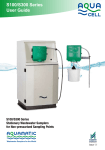
Aquamatic Stationary
Wastewater Samplers
User Guide
SECTIONS
CONTENTS
KEY FIGURES
WARRANTY
0
CONTENTS OF PACKAGE
1
INTRODUCTION
2
CHOOSING A SITE
3
PREPARING THE SITE
4
INSTALLATION
5
OPERATION
6
MAINTENANCE
7
TECHNICAL SPECIFICATION
8
CONTENTS
CONTENTS
AQUACELL S50/S100/S200/S300 SERIES WASTEWATER
SAMPLER - NEW PRODUCT WARRANTY..................................i
Discrepancies in Content of Consignment / Damage in Transit........ ii
Storage of the Sampler Prior to Installation....................................... ii
CONTENTS OF PACKAGE..........................................................1.1
Samplers - S50...............................................................................1.2
Samplers - S100. ...........................................................................1.3
Samplers - S200. ...........................................................................1.4
Samplers - S310 / S320................................................................1.5
Samplers - Aquacell S310H/S320H...........................................1.6
Sample Collection Vessels (SCV's)..........................................1.7
Single Container Options................................................................1.7
Bottler Options . .............................................................................1.7
Removable Bottlers..........................................................................1.7
Integral Bottlers. ..............................................................................1.8
Optional Equipment - Electrical................................................1.8
Optional Equipment - Mechanical. .........................................1.10
Consumable Spares...................................................................1.10
INTRODUCTION.............................................................................2.1
The Sampling Process. ...............................................................2.1
Aquacell S50/S100/S200/S300(Series) Samplers..................2.2
Aquacell
Aquacell
Aquacell
Aquacell
S50 Wastewater Sampler................................................2.2
S100 Wastewater Sampler..............................................2.3
S200 Wastewater Sampler..............................................2.3
S300 Series Wastewater Samplers.................................2.4
Aquacell S310 Wastewater Sampler..................................................2.4
Aquacell S320 Wastewater Sampler..................................................2.4
Aquacell S310H Wastewater Sampler................................................2.4
Aquacell S320H Wastewater Sampler................................................2.5
The Pressurised Pipeline Interface (PPI) ......................................2.5
Wastewater Drain..........................................................................2.5
The User Guide..............................................................................2.6
Safety First. ....................................................................................2.6
Infection..........................................................................................2.6
Electrical.........................................................................................2.7
Mechanical.....................................................................................2.7
CHOOSING A SITE........................................................................3.1
Environmental Considerations..................................................3.1
Non-pressurised Sampling Points. ..........................................3.1
Pressurised Sampling Points....................................................3.3
PREPARING THE SITE................................................................4.1
Aquacell S50 Sampler..................................................................4.1
Sampler / Sample Collection Vessel Location . .............................4.2
Gravity Drain (Wastewater) Installation (if required).......................4.2
Electrical Power Supply Installation................................................4.2
(Optional) Ancillary Signal Connection...........................................4.3
Aquacell S100 Sampler. ..............................................................4.5
Sampler / Sample Collection Vessel Location................................4.6
Gravity Drain (Wastewater) Installation (if required).......................4.6
Electrical Power Supply Installation................................................4.6
(Optional) Ancillary Signal Connection...........................................4.7
Aquacell S200 Sampler. ..............................................................4.9
Sampler Location..........................................................................4.10
Electrical Power Supply Installation..............................................4.10
(Optional) Ancillary Signal Connection.........................................4.10
Aquacell S300 Series Samplers..............................................4.12
Sampler Location..........................................................................4.14
Gravity Drain (Condensate) Installation (if required)....................4.14
(Optional) Condensate Evaporator Tray Installation.....................4.14
Gravity Drain (Wastewater) Installation (if required).....................4.14
Gravity Drain for Self Emptying Bottler (if required).....................4.15
Electrical Power Supply Installation..............................................4.15
Auxiliary Equipment Installation....................................................4.15
(Optional) Ancillary Signal Connection.........................................4.15
(Optional) Auxiliary Equipment Mounting Plate............................4.16
(Optional) Auxiliary Equipment Enclosure....................................4.16
CONTENTS
Condensate Drain (S320 & S320H only). ................................2.6
Pressurised Pipeline Interface (PPI) - Standard Version..4.20
CONTENTS
PPI Location.................................................................................4.21
Gravity Drain Installation..............................................................4.21
Installing the Pressure Tapping....................................................4.21
Electrical Power Supply Installation..............................................4.21
Pressurised Pipeline Interface (PPI) - S300 Version..........4.22
Gravity Drain Installation..............................................................4.23
Installing the Pressure Tapping....................................................4.23
INSTALLATION...............................................................................5.1
Aquacell S50 Sampler . ...............................................................5.1
Sampler..........................................................................................5.1
Sample Collection Vessel (SCV)....................................................5.2
Electrical Connections to the Sampler Module...............................5.2
Aquacell S100 Sampler ..............................................................5.4
Sampler..........................................................................................5.4
Sample Collection Vessel (SCV)....................................................5.4
Electrical Connections to the Sampler Module...............................5.5
Aquacell S200 Series Samplers................................................5.7
Sampler..........................................................................................5.7
Sample Collection Vessel (SCV)....................................................5.7
Electrical Connections to the Sampler Module...............................5.8
Aquacell S300 Series Samplers..............................................5.10
Sampler........................................................................................5.10
Sample Collection Vessel (SCV)..................................................5.10
Single Containers / Detachable Bottlers...........................................5.10
Integral Bottlers. ............................................................................ 5.11
(Optional) Auxiliary Equipment Mounting Plate............................ 5.11
(Optional) Auxiliary Equipment Enclosure.................................... 5.11
Pressurised Pipeline Interface - Standard Version............5.13
Pressurised Pipeline Interface - S300 Version....................5.13
Intake Hose Installation.............................................................5.14
Non Pressurised Sampling Points................................................5.14
Installation Procedure:....................................................................5.14
S50 Sampler..............................................................................5.15
S100 and S200 Samplers............................................................5.15
S300 Series Samplers.................................................................5.16
Pressurised Sampling Points - Samplers incorporating The
(Optional) Back-up Battery Installation.................................5.18
S50 / S200 Samplers.....................................................................5.18
S100 Sampler. ..............................................................................5.18
S300 Series Samplers....................................................................5.18
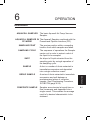
OPERATION....................................................................................6.1
Definitions.......................................................................................6.1
Basic Operations. .........................................................................6.3
Controlling the Sampler..................................................................6.3
Operating Buttons............................................................................6.3
Programming Buttons.......................................................................6.3
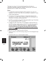
Switching on the Power..................................................................6.4
Sampler Module, Initialization Sequence ...........................................6.4
S50 / S100 / S200 / S310 (Basic Model) Samplers. .........................6.4
S310 with optional Beacon and/or Interior Light / S310H / S320 / S320H
Samplers. ....................................................................................6.4
Heating / Cooling Component Start-up...............................................6.5
S50 / S100 / S310 Samplers..........................................................6.5
S200 Samplers.............................................................................6.5
S310H / S320 / S320H Samplers...................................................6.6
Switching on the (Optional) Back-Up Battery.................................6.7
Basic (For S50, S100 and S200 Samplers)...................................6.7
S300 Series. ...................................................................................6.7
Taking a Spot Sample....................................................................6.7
Basic Aquacell Sampler....................................................................6.8
Aquacell Sampler in PPI mode..........................................................6.9
Setting the Purge Times - Basic Aquacell Sampler......................6.10
Setting the Flush Time - PPI........................................................ 6.11
Removing / Refitting the Sample Chamber..................................6.13
Changing the Sample Shot Volume..............................................6.15
Precision Sample Shot Volumes..................................................6.16
Sampling Frequency.....................................................................6.16
Distributor Pipe Alignment............................................................6.17
Advanced operations.................................................................6.18
Programming the Sampler............................................................6.19
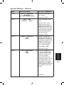
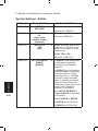
System Settings - General...........................................................6.21
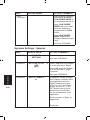
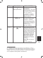
Systems Settings - Sampler.........................................................6.22
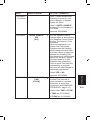
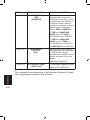
System Settings - Bottler..............................................................6.28
CONTENTS
Pressurised Pipeline Interface (PPI).............................................5.17
Installation Procedure:....................................................................5.17
CONTENTS
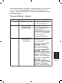
Program Settings - Sampler.........................................................6.31
Special Options............................................................................6.34
Program Settings - Bottler............................................................6.34
Special Options Indication............................................................6.35
Running the Program. ...............................................................6.36
Taking Spot Samples During a Sampling Program......................6.37
Bottlers..........................................................................................6.38
Detachable Bottlers......................................................................6.38
Self-Emptying Bottler....................................................................6.38
Leaving the Sampler to Operate Automatically..................6.40
Returning to Collect Samples..................................................6.40
Data Logging / Communication Facilities............................6.41
Sample Temperature Monitoring (Option).....................................6.41
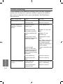
Sampling Events...........................................................................6.42
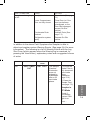
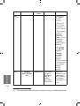
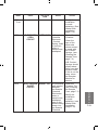
Warning Events............................................................................6.44
Warning Event occurances, out of the Event Logging Phase..............6.50
Warning Event occurances during the Event Logging Phase..............6.50
Warning Event occurances whilst a Spot Sample is being taken, during
the Event Logging Phase................................................................6.51
Viewing the Program Settings and Progress................................6.51
Escaping from the VIEW status.......................................................6.54
Downloading the Samplers Event and Sample Temperature logs to
a Computer...................................................................................6.55
Initial Preparations.........................................................................6.55
Stage 1......................................................................................6.55
Stage 2......................................................................................6.56
Configuring a Hyper Terminal Connection.........................................6.56
Starting a Hyperterminal Download Session.....................................6.57
Giving the Sampler a name. ...........................................................6.58
Configuring the text file in which the data will be captured. ................6.58
Downloading the Event Log............................................................6.59
Downloading the Sample Temperature Log. .....................................6.60
Closing down.................................................................................6.62
A Few simple DO’S and DON’TS when operating your
Sampler..........................................................................................6.63
Do's..............................................................................................6.63
Don’ts...........................................................................................6.63
MAINTENANCE..............................................................................7.1
General. ...........................................................................................7.1
Cleaning The Sample Tract........................................................7.2
Intake Hose Assembly ...................................................................7.3
Sample Chamber / Chamber Top ..................................................7.3
Sample Collection Vessel...............................................................7.4
10 Litre Polypropylene Container Format:. .........................................7.4
12 x 0.75 Litre Glass Bottler Format:. ................................................7.4
12 x 1 Litre P.E.T. Bottler Format:......................................................7.4
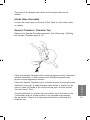
Bottler Distributor Pipe....................................................................7.4
Keeping the Inside of the Sampler Module Dry....................7.4
Test Mode........................................................................................7.5
Breakdown Service.......................................................................7.8
On-Site Service..............................................................................7.8
Back to Base Service.....................................................................7.9
Sampler Module. .............................................................................7.9
Removable Bottler. ..........................................................................7.9
Other faulty hardware which is readily detachable...............................7.9
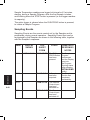
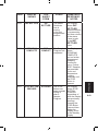
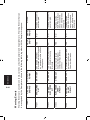
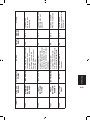
Trouble Shooting. .......................................................................7.10
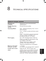
TECHNICAL SPECIFICATIONS..................................................8.1
Aquacell Sampler Module...........................................................8.1
Materials of construction.................................................................8.2
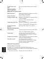
Mechanical Features......................................................................8.2
Optional Connections.....................................................................8.2
Ancillary Signal Connection. .............................................................8.2
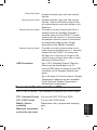
USB Connection..............................................................................8.3
Pressurised Pipeline Interface (PPI)........................................8.3
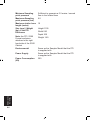
Aquacell Wastewater Sampler Model Range.........................8.5
Standards Compliance...................................................................8.5
Data Table......................................................................................8.5
CONTENTS
Maintenance Contract....................................................................7.1
User Maintenance..........................................................................7.1
KEY FIGURES
KEY
FIGURES
Figure 3.A: Intake Hose Geometry.................................................3.2
Figure 4.A: Installation Drawing, S50 Sampler...............................4.1
Figure 4.B: Connecting the Sampler to Typical Auxiliary Equipment,
Aquacell S50 Sampler....................................................................4.4
Figure 4.C: Installation Drawing, S100 Sampler............................4.5
Figure 4.D: Connecting the Sampler to Typical Auxiliary Equipment,
Aquacell S100 Sampler..................................................................4.8
Figure 4.E: Installation Drawing, S200 Sampler.............................4.9
Figure 4.F: Connecting the Sampler to Typical Auxiliary Equipment,
Aquacell S200 Sampler................................................................ 4.11
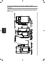
Figure 4.G: Installation Drawing, S300 Sampler - Top, Left Side and
Front Views .................................................................................4.12
Figure 4.H: Installation Drawing, S300 Sampler - Right Side and
Rear Views...................................................................................4.13
Figure 4.I: Connecting the Sampler to Typical Auxiliary Equipment,
Aquacell S300 Series Samplers...................................................4.18
Figure 4.J: Wiring Details - (Optional) Auxiliary Equipment Mounting
Plate/(Optional) Auxiliary Equipment Enclosure...........................4.19
Figure 4.K: Installation Drawing, Pressurised Pipeline Interface Standard Version..........................................................................4.20
Figure 4.L: Installation Drawing, Pressurised Pipeline Interface S300 Version................................................................................4.22
Figure 5.A: Wiring Details, Aquacell S50 Sampler.........................5.3
Figure 5.B: Wiring Details, Aquacell S100 Sampler.......................5.6
Figure 5.C: Wiring Details, Aquacell S200 Sampler.......................5.9
Figure 5.D: Wiring Details, Aquacell S300 Series Samplers........5.12
Figure 6.A: Front Panel Controls of The Sampler Unit...................6.3
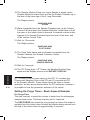
Thank you for choosing an Aquamatic Wastewater Sampler. The
Sampler, when properly used and maintained, should give many
years of reliable service. To mark our confidence in your new
Aquamatic Sampler it comes with the following guarantee:
Electrical and/or mechanical defects occurring during the 12 months
from the date of invoice will be rectified free of charge provided the
defective item is returned carriage paid to the supplier during this 12
month warranty period.
Details of Breakdown Service can be found in the MAINTENANCE
section of this User Guide (see page 7.8 for further information).
Please read this User Guide carefully, as neither Aquamatic Ltd., nor
its agents accept responsibility for any damage or defect caused by
misuse, abuse, neglect or incorrect operation.
Aquamatic Wastewater Samplers are subject to continuous
development and improvement. Components and specifications may
change without notice.
One copy of the User Guide is included with each Sampler. This
is intended to assist the reader in the effective application of the
product and although the information contained is given in good faith,
Aquamatic Ltd., does not accept responsibility or liability for any
loss or damage arising from the use of information provided or from
information being omitted.
WARRANTY
AQUACELL S50/S100/S200/S300
SERIES WASTEWATER SAMPLER NEW PRODUCT WARRANTY
i
WARRANTY
ii
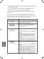
In any event Aquamatic Ltd., does not accept liability for any
consequential loss or damage arising from the use or failure of
the product or any information provided, including, but not limited
to, economic or financial loss, damage to peripheral equipment or
products, loss of use, productivity or time.
Discrepancies in Content of Consignment / Damage in
Transit
On receipt of the consignment it is important to check the following:
• That the consignment matches the supplier’s delivery note, and in
turn the items specified on your purchase order. See CONTENTS
OF PACKAGE page 1.1 for details.
• That no transit damage has occurred.
It is important to report any discrepancies or transit damage
within 48 hours, otherwise transit insurance may be invalidated.
In any event the cost of rectification would not be covered under
the product warranty.
Note: (S200/S300 Series) The packaging material protecting the
Sampler can be removed for inspection purposes (temporarily if
appropriate) without the need to remove the Sampler from its palette.
© Copyright 2011 Aquamatic Ltd.
All rights reserved.
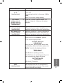
Storage of the Sampler Prior to Installation
The Sampler should be kept in a dry indoor storage area until it is
ready to be installed.
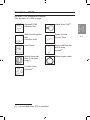
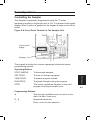
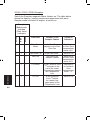
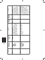
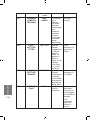
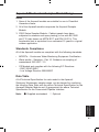
CONTENTS OF PACKAGE
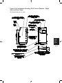
The following is an illustrated list of most of the items appearing on
the price list. This is a usefull means of identifying the items ordered,
in order to ensure your order has been executed correctly.
Some price list items are omitted as they are fully integrated and not
able to be depicted visually. Price list items are also omitted, when an
illustration serves no useful purpose.
CONTENTS
OF
PACKAGE
1
1.1
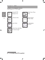
Samplers - S50
Aquacell S50 Wastewater Sampler
Part Number CL-1210-voltage
CONTENTS
OF
PACKAGE
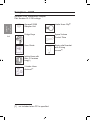
1.2
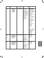
Aquacell S50
Sampler Unit
Intake Hose Clip[1]
(S50)
2 Anchor bolts
Spare Volume
Control Tube
User Guide
2 Intake Hose
Anchors[1]
Intake Hose with filter
(5 metres long)[1]
[1] not included when PPI is specified
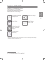
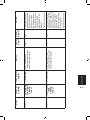
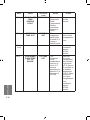
Samplers - S100
Aquacell S100
Sampler Unit
Intake Hose Clip[1]
Wall mounting plate
with
4 Anchor bolts
Spare Volume
Control Tube
User Guide
Strain relief bracket
with 2 fixing
screws[1]
Intake Hose with
filter (10 metres
long)[1]
Mains supply cable
2 Intake Hose
Anchors[1]
[1] not included when PPI is specified
CONTENTS
OF
PACKAGE
Aquacell S100 Wastewater sampler
Part Number: CL-1220-voltage
1.3
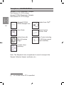
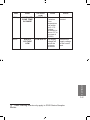
Samplers - S200
Aquacell S200 Wastewater Sampler
Part Number CL-1230-voltage
CONTENTS
OF
PACKAGE
1.4
Aquacell S200
Sampler Unit
Intake Hose Clip[1]
Fridge Keys
Spare Volume
Control Tube
User Guide
Strain relief bracket
with 2 fixing
screws[1]
Intake Hose with
filter (10 metres
long)[1]
2 Intake Hose
Anchors[1]
[1] not included when PPI is specified
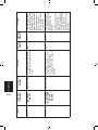
Samplers - S310 / S320
Aquacell S310 Wastewater Sampler
Part Number CL-1240-voltage
Aquacell S310/S320
Sampler Unit
Intake Hose Clip[1]
CONTENTS
OF
PACKAGE
Aquacell S320 Wastewater Sampler
Part Number CL-1260-voltage
1.5
User Guide
Spare Volume
Control Tube
Intake Hose with
filter (10 metres
long)[1]
2 Intake Hose
Anchors[1]
Note: The Sampler's lower compartment is used to transport the Sample
Collection Vessel, ancillaries, etc...
[1] not included when PPI is specified
Samplers - S310H/S320H
Aquacell S310H Wastewater Sampler
Part Number CL-1250-voltage
Aquacell S320H Wastewater Sampler
Part Number CL-1270-voltage
CONTENTS
OF
PACKAGE
Aquacell S310H/
S320H Sampler Unit
Intake Hose Clip[1]
User Guide
Spare Volume
Control Tube
Intake Hose with
filter (10 metres
long)[1]
Air Cowls (including
9, M4 fixing screws/
nylon washers)
1.6
2 Intake Hose
Anchors[1]
Note: The Sampler's lower compartment is used to transport the
Sample Collection Vessel, ancillaries, etc...
[1] not included when PPI is specified
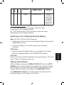
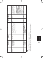
Sample Collection Vessels (SCV's)
Single Container Options
Part Number CL-3005
25 Litre Polyethylene
Container
Part Number CL-3001
CONTENTS
OF
PACKAGE
10 Litre Polypropylene
Container
Bottler Options
Removable Bottlers
2 x 4.5 Litre Self-Emptying
Polypropylene
Bottler (including expansion
coupling)
Part Number CL-3006
4 x 4.5 Litre Glass Bottler
Part Number CL-3007
4 x 5 Litre HDPE Bottler
Part Number CL-3008
12 x 0.75 Litre Glass Bottler
Part Number CL-3002
1.7
Integral Bottlers
CONTENTS
OF
PACKAGE
12 x 1 Litre PET Bottler
Part Number CL-3003
24 x 1 Litre HDPE Bottler
Part Number CL-3004
2 x 4.5 Litre Self-Emptying
Polypropylene Integral
Bottler (plus additional
integral parts)
Part Number CL-3108
1.8
Optional Equipment - Electrical
Ancillary Signal Connection,
Basic (plus additional
integral parts)
Part Number CL-4004
Back-up Battery / Float
Charger (plus additional
integral parts)
Part Number CL-4024
Beacon
(plus additional Integral
parts)
Part Number CL-4122
Condensate Evaporator
Tray
(plus additional integral
parts)
Part Number CL-4112
-voltage
Part Number CL-4147-voltage
PPI Unit
Pipe Extension
Assembly
4 Anchor bolts
Intake Hose Clip
(PPI)
CONTENTS
OF
PACKAGE
Pressurised Pipeline Interface
- Standard
1.9
Intake Hose (10
metres long)
Pressurised Pipeline Interface
- S300
Intake Hose (10
metres long)
2 PPI Housing Door
Keys
2 PPI Housing Door
Keys
Part Number CL-4120-voltage
Intake Hose Clip
(PPI)
Optional Equipment - Mechanical
CONTENTS
OF
PACKAGE
Auxiliary Equipment
Enclosure (plus additional
integral parts)
Part Number CL-4117
Auxiliary Equipment
Mounting Plate
Part Number CL-4108
Intake Hose Support
Bracket Kit
Part Number CL-4010
Wastewater Drain (plus
additional integral parts)
Part Number CL-4102
1.10
Consumable Spares
Battery, Sampler
Part Number CL-6026
Desiccant Bag
Part Number CL-7009
Sample Chamber
Acrylic
Part Number CL-6164
Glass
Part Number CL-6028
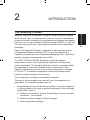
2
INTRODUCTION
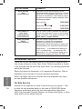
Aquacell Stationary Wastewater Samplers extract individual sample
shots from an open (non pressurised) source, such as a wastewater
channel or vessel, according to a predetermined program and deposit
them into one or more Sample Collection Vessels (SCVs). In this way
the user is provided with a representative sample of the wastewater
discharge.
Each of the Aquacell Samplers is capable of being combined with
a Pressurised Pipeline Interface (PPI), to give the Sampler the
capability of sampling from a Pressurised Sampling Point (Typically a
pipeline, operating at pressures up to 6 Bar)
The S200, S320 and S320H Samplers incorporate sample
temperature control. This is particularly important for biologically
active wastewater. The Sample Collection Vessel is contained within
the temperature controlled, lockable lower compartment of the
Sampler. Samples are stored at an average temperature, between
0°C and 5°C, to minimise degradation during the storage period
between sample extraction and analysis.
The refrigerated housing is automatically defrosted.
The way in which samples are used will vary from application to
application. For example, samples can be:
• Analysed using in-house laboratory facilities – when the objective
of taking samples is to gain a greater knowledge of the discharge
profile with a view to:
a) Reducing the pollution load of the discharge (to meet consent
conditions – for example).
b) Reducing water company effluent charges.
c) Reducing product wastage.
INTRODUCTION
The Sampling Process
2.1
• Sent to a specialist analytical laboratory for analysis - when an
independent assessment of the discharge is required.
• Made available, to the water company receiving and treating the
wastewater, as a source of data on which to base charges. (Selfmonitoring is being increasingly encouraged by water companies
both in the interests of accurate charging and to encourage
dischargers to improve plant efficiency, and so reduce the pollution
load of their discharge.)
INTRODUCTION
2.2
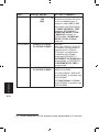
Aquacell S50/S100/S200/S300(Series) Samplers
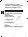
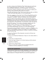
Aquacell S50 Wastewater Sampler
This is a wall mounting automatic sampler, featuring the Aquacell
Sampler Module. The Aquacell S50 is intended for indoor
applications only.
The Sampler is supplied with a
Bracket / Mounting Bolts to facilitate
attachment to a wall or similar flat
vertical surface.
When the Sampler is specified with
a 10 litre Polyethylene Container,
an optional Suspension Bracket
is available which attaches to the
lower edge of the Sampler Module,
and provides a suspension point for
the Container.
All other Detachable Sample Collection Vessels can be used with the
S50 where the installation provides for the SCV to be located suitably
beneath the Sampler.
Whilst the Sampler is suitable for operation at ambient temperatures
between -10˚C and +50˚C, frost protection for the sample is not
provided.
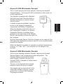
Aquacell S100 Wastewater Sampler
This is a wall mounting automatic sampler, featuring the Aquacell
Sampler Module. The Aquacell S100 is intended for either indoor or
outdoor applications.
Lockable covers are provided to prevent
access to the sampler’s operational
components and Battery Compartment
When the Sampler is specified with a 10
litre Polyethylene Container, an optional
Suspension Bracket is available which
attaches to the lower edge of the Sampler
Module, and provides a suspension point for
the Container.
All other Removable Sample Collection Vessels can be used with the
S50 where the installation provides for the SCV to be located suitably
beneath the Sampler.
Whilst the Sampler is suitable for operation at ambient temperatures
between -10˚C and +50˚C, frost protection for the sample is not
provided.
Aquacell S200 Wastewater Sampler
This is a floor standing automatic Sampler, featuring the Aquacell
Sampler Module, and incorporating sample refrigeration. The
Sampler Module is mounted above the
metal Sample Container Housing. The
Aquacell S200 is intended for heated indoor
applications only.
The door to the temperature controlled
sample container housing is lockable.
The sampler can be used with all of the
Removable Sample Collection Vessels,
except the 2 x 4.5 litre Self-Emptying
Polypropylene Bottler.
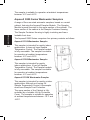
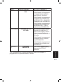
INTRODUCTION
The Sampler is supplied with a Bracket /
Wall Mounting Plate / Mounting Bolts to
facilitate attachment to a wall or similar
vertical surface.
2.3
The sampler is suitable for operation at ambient temperatures
between +5˚C and +40˚C.
Aquacell S300 Series Wastewater Samplers
A range of floor mounted automatic samplers, based on a metal
cabinet, featuring the Aquacell Sampler Module. The Sampler
Module is panel mounted in the upper section of the cabinet. The
lower section of the cabinet is the Sample Container Housing.
INTRODUCTION
2.4
The Sample Container Housing is highly insulating and has a
lockable front door.
The Aquacell S300 Series comprises four primary variants as follows:
Aquacell S310 Wastewater Sampler
This sampler is intended for mainly indoor
applications. It does not have Sample
Temperature Control. The Sampler module
is fully accessible. The sampler is suitable
for operation at ambient temperatures
between +5˚C and +50˚C.
Aquacell S320 Wastewater Sampler
This sampler is intended for mainly
indoor applications. It has full Sample
Temperature Control. The Sampler module
is fully accessible. The sampler is suitable
for operation at ambient temperatures
between +5˚C and +40˚C.
Aquacell S310H Wastewater Sampler
This sampler is intended for mainly outdoor
applications. Although not having full
Sample Temperature Control, this sampler
does have Sample Frost Protection.
The upper section of the Cabinet is fully
enclosed by a lockable Lift-Up Protection
Cover. The sampler is suitable for operation
at ambient temperatures between -10˚C and
+50˚C.
Aquacell S320H Wastewater Sampler
This sampler is intended for mainly outdoor applications. It has full
Sample Temperature Control. The upper section of the Cabinet is
fully enclosed by a lockable Lift-Up Protection Cover. The sampler
is suitable for operation at ambient temperatures between -10˚C and
+50˚C.
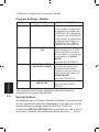
This is an equipment which either stands along-side the Sampler
(PPI - Standard Version, specified for use with S50, S100 and S200
Samplers), or is integral to the Sampler (PPI - S300 Version used
with S300 Series Samplers). The PPI is an interface between the
Sampler and a pressurised Sampling Point. It gives the Sampler the
ability to extract representative samples from pipelines at pressures
up to 6 bar.
The PPI - Standard is wall mounted and is supplied with mounting
bolts to facilitate attachment to a wall or similar vertical surface.
The PPI - S300 Version is fully integrated with the Sampler cabinet.
The PPI is suitable for operation at ambient temperatures between
-10˚C and +50˚ (when the optional Anti-Condensation Heater is
fitted).
Wastewater Drain
All S300 series samplers can be specified with a Wastewater Drain.
When a Sampler is supplied with a Wastewater Drain, the lower
compartment of the Sampler provides a useful discharge point for
surplus samples, accidental spillage etc.
When a Sampler is specified with a Self-Emptying Bottler, a
Wastewater Drain is included.
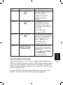
Samplers incorporating a Wastewater Drain are supplied with a “P”
Trap (To accommodate the “P” Trap, the Sampler is fitted with a
special deep Cabinet Base, which raises the overall height of the
Sampler by 140mm). The purpose of the water trap is to prevent cold
air leaking from the Sampler’s Lower Compartment and adversely
effecting temperature control (S320 & S320H only). It also provides a
screen against intrusion from insects etc.
INTRODUCTION
The Pressurised Pipeline Interface (PPI)
2.5
Condensate Drain (S320 & S320H only)
INTRODUCTION
2.6
A Condensate Drain is incorporated in S320 and S320H samplers
(Samplers with sample temperature control) unless a wastewater
drain is specified. The Condensate Drain outlet discharges the
small volume of condensate water produced by the refrigeration
system in the Samplers Lower Compartment. The Condensate Drain
incorporates a water trap within the Base of the Sampler Cabinet,
to prevent cold air leaking from the Sampler’s Lower Compartment
and adversely effecting temperature control. It also provides a screen
against intrusion from insects, etc. When a Wastewater Drain is
specified, it replaces the Condensate Drain.
The User Guide
The User Guide has been written to accommodate the complete
Aquacell S50/S100/S200/S300 product range. Much of the
information supplied applies equally to all formats, however, where
information relates to a specific format, collection vessel or ancillary
then it is given under a separate heading so the reader can readily
focus on information relating to his particular Sampler.
The Aquacell S50/S100/S200/S300 sampling system is designed
for ease of operation and maintenance. If you follow the instructions
given in this guide you should quickly be able to benefit from the
availability of truly representative wastewater samples.
Safety First
Infection
Aquacell S50/S100/S200/S300 Wastewater Samplers and Sample
Collection Vessels have been designed to minimise the risk of
operator contact with the potentially hazardous wastewater medium,
however great care should always be exercised when working in
close proximity to wastewater. Particular attention should be paid to
the following points:
1. Wash hands thoroughly after handling contaminated Sampler
parts.
2. Do not allow wastewater to come into contact with any open
wounds or skin abrasions.
3. If any Glass has become cracked or chipped replace immediately
to avoid the risk of cuts.
Electrical
Aquacell S50/S100/S200/S300 Wastewater Samplers are powered by
an AC mains supply. As all mains voltage terminals are safely housed
behind protective covers then contact with dangerous voltages is
avoided.
Care should be taken, whilst the Sampler is in operation, to avoid
trapping fingers in the pinch valve assembly.
The Sampler may (if ordered) have a Glass Sample Chamber and/
or Glass Sample Collection Vessels, so do take great care when
handling as these can be very slippery when wet.
Caution: Do not attempt to carry out any maintenance on the
sampler other than that described in the Maintenance Section of
this User Guide.
INTRODUCTION
Mechanical
2.7
INTRODUCTION
2.8
3
CHOOSING A SITE
• The Sampler should not be situated in a classified hazardous
area.
Environmental Considerations
See Technical Specification (page 8.8), for IP Rating and Ambient
Temperature Range.
S50 and S200 Samplers are only suitable for indoor sites.
S310 and S320 Samplers are mainly intended for indoor sites.
S100, S310H and S320H Samplers are suitable for indoor /
outdoor sites
The Pressurised Pipeline Interface is suitable for outdoor use
provided the Anti-Condensation Heater is specified, however
as liquid remains in the Intake hose (The hose connecting the
Pipeline Tapping Point to the PPI) between samples, trace
heating of this hose will be necessary, if freezing ambient temperatures are likely to be encountered.
When choosing a site, consideration should be given to the
possibility, that solar radiation could cause the Sampler to rise
above its specified maximum temperature. If this possibility
exists, then solar screening should be provided.
Non-pressurised Sampling Points
S50 / S100 / S200 / S300(Series) Samplers are all suitable for use
with Non-pressurised Sampling Points unless specified with the
Pressurised Pipeline Interface. The criteria to consider when using
a sampler to sample from a non-pressurised Sampling Point are as
follows:
CHOOSING A
SITE
• The Sampler should be installed as close to the Sampling Point as
possible to minimise the potential for cross-contamination between
successive samples.
3.1
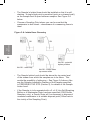
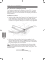
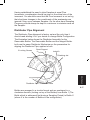
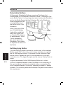
• The Sampler’s Intake Hose should be installed so that it is selfdraining. A single high point is permitted (such as a channel wall),
as the sample tract is open between samples. See Figure 3.A
below.
• Choose a Sampling Point where you can be sure that the
wastewater is well mixed – downstream of a measuring flume is
ideal.
Figure 3.A: Intake Hose Geometry
OK
OK
CHOOSING A
SITE
3.2
Not OK - potential
siphon problem
Not OK - water trap
Not OK - intake takes
up excess solids
• The Sample Intake Level should be above the top water level
of the stream from which the samples are to be taken. This
avoids the possibility of siphoning – See Figure 3.A above. Also
see the Sampler Installation Drawing of the Sampler specified,
in PREPARING THE SITE (Section 4), for details of the Sample
Intake Level.
• If the Sampler is to be operated with a 2 x 4.5 Litre Self-Emptying
Bottler or a Wastewater Drain has been specified (S300 Series
Samplers, only), a Gravity Drain will be necessary to dispose of
unwanted wastewater to a suitable disposal point (Often back to
the vicinity of the Sampling Point).
Pressurised Sampling Points
Samplers specified with the Pressurised Pipeline Interface (PPI) are
suitable for sampling from pressurised Sampling Points (typically
pipelines). Considerations when using a sampler to sample from a
pressurised Sampling Point are as follows:
• The Sampler / PPI can be positioned above or below the Sampling
Point as required
• The Intake Hose routing is non-critical.
• Choose a Sampling Point where you can be sure that the
wastewater is well mixed and a representative sample will always
be available.
o If there is likely to be any sediment at the bottom of
the pipe then it may be preferable to tap into the side
of the pipe.
o If the pipeline is not always full then a tapping point
below minimum liquid level should be chosen.
• Minimum Pipeline Tapping Point Pressure - The pressure in the
pipeline at the tapping point must always be sufficient to create
a flow of 0.5m/s in the Ø12mm bore Intake Hose. Consideration
should be given to the hydro-static head created by the relative
height of the Sampling Point with the Flush Discharge Level of the
PPI. See the PPI installation drawing, page 4.20 or page 4.22 for details.
A Sampling Point above the Flush Discharge Level of the PPI will
add to the pipeline pressure and a Sampling Point below the Flush
Discharge Level of the PPI will subtract from the pipeline pressure.
CHOOSING A
SITE
• S320 and S320H Samplers, only - These samplers feature sample
refrigeration and need to dispose of a small volume of condensate
water. Samplers fitted with a Wastewater Drain are able to dispose
of Condensate Water. Samplers not fitted with a Wastewater
Drain, have a Condensate Water Drain. There are 3 alternative
methods of disposal of water discharging from the Condensate
Water Drain, which are as follows:
o Construct a Gravity Drain from 21.5mm O/D plastic
pipe.
o Deploy a Condensate Evaporator Tray (Part Number
CL-4112). (Note – This should have been specified
with the Sampler order as it cannot be retro-fitted).
o (Outdoor Installations) Simply allow the condensate
water to soak away into the surrounding earth.
3.3
• Maximum Pipeline Tapping Point Pressure - The maximum
permissible pipeline pressure is 6 Bar.
• A Gravity Drain will be necessary to dispose of unwanted
wastewater from the PPI to a suitable disposal point.
• If the Sampler is to be operated with a 2 x 4.5 Litre Self-Emptying
Bottler or a Wastewater Drain has been specified (S300 Series
Samplers, only), an additional Gravity Drain will be necessary to
dispose of unwanted wastewater to a suitable disposal point[1].
CHOOSING A
SITE
3.4
• S320 and S320H Samplers, only - These samplers feature sample
refrigeration and need to dispose of a small volume of condensate
water. Samplers fitted with a Wastewater Drain are able to dispose
of Condensate Water. Samplers not fitted with a Wastewater
Drain, have a Condensate Water Drain. There are 3 alternative
methods of disposal of water discharging from the Condensate
Water Drain, which are as follows:
o Construct an additional Gravity Drain from 21.5mm
O/D plastic pipe[1]
o Deploy a Condensate Evaporator Tray (Part Number
CL-4112). (Note – This should have been specified
with the Sampler order as it cannot be retro-fitted).
o (Outdoor Installations) Simply allow the condensate
water to soak away into the surrounding earth.
[1] It may be possible to use the PPI drain for this purpose
4
PREPARING THE SITE
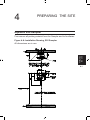
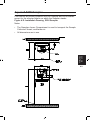
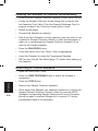
Aquacell S50 Sampler
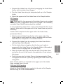
First remove all packing material from the Sampler and its Ancillaries
Figure 4.A: Installation Drawing, S50 Sampler
PREPARING
THE SITE
All dimensions are in mm.
4.1
Sampler / Sample Collection Vessel Location
A wall or similar flat surface is required, on which to mount the
Sampler. The Sampler should be positioned above the Sample
Collection Vessel (SCV) such that the Samplers Pinch Valve Tube,
is able to engage the inlet of the SCV to a depth of 60mm. The
Sampler / SCV should be positioned at a convenient height for
operator access. A nominal dimension of 1230mm is suggested, for
the height of the top edge of the Sampler above the floor. A shelf
may need to be provided for the SCV.
If the Sampler is to be used with a 2 x 4.5 Litre Self-Emptying
Bottler, then a pair of Guide Rails for the Bottler, fitted to the Bottler
Support Shelf, may be usefull in ensuring that the Bottler Drain Spigot
engages readily with the Expansion Coupling / Gravity Drain, when
the Bottler is slid into position.
Gravity Drain (Wastewater) Installation (if required)
Construct the drain from 56mm O/D, 50mm I/D plastic pipe.
PREPARING
THE SITE
4.2
An expansion coupling is provided with the Bottler, which has a
solvent weld joint at one end and a chevron seal at the other.
Terminate the drainpipe by solvent welding the pipe end to the
expansion coupling. The expansion coupling should be rigidly
supported (possibly by the drainpipe connecting to it) such that the
chevron seal aligns with the Drain Spigot at the base of the rear
face of the Bottle Carrier, when the Bottler is in position beneath the
Sampler. The rubber chevron seal provides a removable coupling for
the Bottler
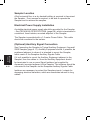
Electrical Power Supply Installation
A suitable electrical supply should be provided for the Sampler - See
TECHNICAL SPECIFICATION (page 8.8) which is terminated in a
switched fused Isolator, mounted adjacent to the Sampler.
A 1.8 metre Power Cable is provided which emanates from the
bottom rear of the Sampler Module. This cable should be connected
to a suitable Switched, Fused Isolator.
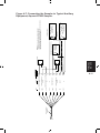
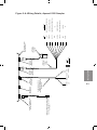
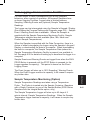
(Optional) Ancillary Signal Connection
See Connecting the Sampler to Typical Auxiliary Equipment, Aquacell
S50 Sampler (page 4.4). Auxiliary Equipment should, if possible, be
positioned adjacent to where it is intended to mount the Sampler,
within reach of the Samplers Ancillary Signals Cable.
Cables to / from the Auxiliary Equipment may need to be terminated
in one or more Signal Isolators (Not supplied by Aquamatic) mounted
adjacent to the Sampler. The isolators should be connected to the
Sampler via the Samplers Ancillary Signals Cable.
PREPARING
THE SITE
Isolators are necessary to protect the Samplers inputs / outputs from
damaging electrical transients, which are sometimes induced in long
cables.
4.3
$1&,//$5< 6,*1$/
&$%/( 127( )/2: ,3
9
5('
%/$&.
'$7$ /2**(5 (7&
$/$50 $1181&,$725 (7&
5(/$< &217$&7
1250$//< 23(1
92/7 )5((
5(027( &21752/ 3803 21 2)) (7&
)/2:0(7(5 :,7+ )/2: 5$7(
$1$/2*8( 6,*1$/
,62/$7(' P$
)/2:0(7(5 :,7+ ,17(*5$7(' )/2:
,038/6( 6,*1$/
1250$//< 23(1 92/7 )5((
5(/$< &217$&7
)/2:0(7(5 $
)/2:0(7(5 % 127( 127(6
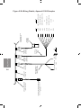
6833/,(' :+(1 $1&,//$5< 6,*1$/ &211(&7,21 ,6 63(&,),('
$/7(51$7,9( )/2:0(7(5 % &211(&7,216 6+2:1 '277('
2873876 $5( 1250$//< 23(1 92/7 )5(( 5(/$< &217$&76 5$7(' $7 9 '& $
&217$&76 $5( &/26(' :+(1 7+( 6<67(0 ,6 +($/7+<
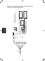
&211(&7,1* 7+( 6$03/(5 72 7<3,&$/ $8;,/,$5< (48,30(17 6 6 6 6$03/(56
6$03/( $&48,5(' 23 $
127( 5(027( &21752/ ,3
9
<(//2:
*5((1
%/8(
:+,7( 6$03/(5 :$51,1* 23 $ 127(6 6$03/( $&48,5(' 23 %
127( 6$03/(5 :$51,1* 23% 127(6
9,2/(7
%52:1
)81&7,21
$8;,/,$5< (48,30(17
&211(&7,216
PREPARING
THE SITE
4.4
:,5(
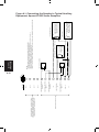
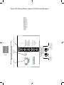
Figure 4.B: Connecting the Sampler to Typical Auxiliary
Equipment, Aquacell S50 Sampler
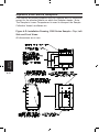
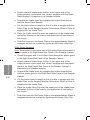
Aquacell S100 Sampler
First remove all packing material from the Sampler and its Ancillaries
Figure 4.C: Installation Drawing, S100 Sampler
Notes:
• All dimensions are in mm.
PREPARING
THE SITE
• Shown with a 10 Litre Container and (optional) Suspension
Bracket.
4.5
Sampler / Sample Collection Vessel Location
A wall or similar flat surface is required, on which to mount the
Sampler. The Sampler should be positioned above the Sample
Collection Vessel (SCV) such that the Samplers Pinch Valve Tube,
is able to engage the inlet of the SCV to a depth of 60mm. The
Sampler / SCV should be positioned at a convenient height for
operator access. A nominal dimension of 1230mm is suggested, for
the height of the top edge of the Sampler above the floor. A shelf
may need to be provided for the SCV.
If the Sampler is to be used with a 2 x 4.5 Litre Self-Emptying
Bottler, then a pair of Guide Rails for the Bottler, fitted to the Bottler
Support Shelf, may be usefull in ensuring that the Bottler Drain Spigot
engages readily with the Expansion Coupling / Gravity Drain, when
the Bottler is slid into position.
Gravity Drain (Wastewater) Installation (if required)
Construct the drain from 56mm O/D, 50mm I/D plastic pipe.
PREPARING
THE SITE
4.6
An expansion coupling is provided with the Bottler, which has a
solvent weld joint at one end and a chevron seal at the other.
Terminate the drainpipe by solvent welding the pipe end to the
expansion coupling. The expansion coupling should be rigidly
supported (possibly by the drainpipe connecting to it) such that the
chevron seal aligns with the Drain Spigot at the base of the rear
face of the Bottle Carrier, when the Bottler is in position beneath the
Sampler. The rubber chevron seal provides a removable coupling for
the Bottler
Electrical Power Supply Installation
A suitable electrical supply should be provided for the Sampler - See
TECHNICAL SPECIFICATION, (page 8.8), which is terminated in a
switched fused Isolator, mounted adjacent to the Sampler.
A 1.8 metre Power Cable is provided which connects to the bottom
rear of the Sampler Module. This cable should be connected to the
isolator.
(Optional) Ancillary Signal Connection
See Connecting the Sampler to Typical Auxiliary Equipment, Aquacell
S100 Sampler (page 4.8). Auxiliary Equipment should, if possible, be
positioned adjacent to where it is intended to mount the Sampler,
within reach of the Samplers Ancillary Signals Cable.
Cables to / from the Auxiliary Equipment may need to be terminated
in one or more Signal Isolators (Not supplied by Aquamatic) mounted
adjacent to the Sampler. The isolators should be connected to the
Sampler via the Samplers Ancillary Signals Cable.
PREPARING
THE SITE
Isolators are necessary to protect the Samplers inputs / outputs from
damaging electrical transients, which are sometimes induced in long
cables.
4.7
$1&,//$5< 6,*1$/
&$%/( 127( )/2: ,3
9
5('
%/$&.
'$7$ /2**(5 (7&
$/$50 $1181&,$725 (7&
5(/$< &217$&7
1250$//< 23(1
92/7 )5((
5(027( &21752/ 3803 21 2)) (7&
)/2:0(7(5 :,7+ )/2: 5$7(
$1$/2*8( 6,*1$/
,62/$7(' P$
)/2:0(7(5 :,7+ ,17(*5$7(' )/2:
,038/6( 6,*1$/
1250$//< 23(1 92/7 )5((
5(/$< &217$&7
)/2:0(7(5 $
)/2:0(7(5 % 127( 127(6
6833/,(' :+(1 $1&,//$5< 6,*1$/ &211(&7,21 ,6 63(&,),('
$/7(51$7,9( )/2:0(7(5 % &211(&7,216 6+2:1 '277('
2873876 $5( 1250$//< 23(1 92/7 )5(( 5(/$< &217$&76 5$7(' $7 9 '& $
&217$&76 $5( &/26(' :+(1 7+( 6<67(0 ,6 +($/7+<
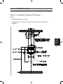
&211(&7,1* 7+( 6$03/(5 72 7<3,&$/ $8;,/,$5< (48,30(17 6 6 6 6$03/(56
6$03/( $&48,5(' 23 $
127( 5(027( &21752/ ,3
9
<(//2:
*5((1
%/8(
:+,7( 6$03/(5 :$51,1* 23 $ 127(6 6$03/( $&48,5(' 23 %
127( 6$03/(5 :$51,1* 23% 127(6
9,2/(7
%52:1
)81&7,21
$8;,/,$5< (48,30(17
&211(&7,216
PREPARING
THE SITE
4.8
:,5(
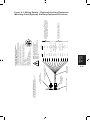
Figure 4.D: Connecting the Sampler to Typical Auxiliary
Equipment, Aquacell S100 Sampler
Aquacell S200 Sampler
First remove all packing material from the Sampler and its Ancillaries
except for the wooden palette on which the Sampler stands.
Figure 4.E: Installation Drawing, S200 Sampler
Notes:
• The Samplers Lower Compartment is used to transport the Sample
Collection Vessel, ancillaries etc.
PREPARING
THE SITE
• All dimensions are in mm.
4.9
Sampler Location
A flat horizontal floor in a dry heated building is required to free-stand
the Sampler. Front access is required, to be able to operate the
Sampler and to retrieve the samples.
Electrical Power Supply Installation
A suitable electrical power supply should be provided for the Sampler
– See TECHNICAL SPECIFICATION, (page 8.8), which is terminated in
a switched, fused isolator, mounted adjacent to the Sampler.
The Sampler is provided with a 1.5 metre Power Cable. This cable
should be connected to the isolator.
(Optional) Ancillary Signal Connection
See Connecting the Sampler to Typical Auxiliary Equipment, Aquacell
S200 Sampler (page 4.11). Auxiliary Equipment should, if possible, be
positioned adjacent to where it is intended to mount the Sampler,
within reach of the Samplers Ancillary Signals Cable.
PREPARING
THE SITE
4.10
If it isn't possible to mount the Auxiliary Equipment adjacent to the
Sampler, then the cables to / from the Auxiliary Equipment should
be terminated in one or more Signal Isolators (not supplied by
Aquamatic) mounted adjacent to the Sampler. The isolators should be
connected to the Sampler via the Samplers Ancillary Signals Cable.
Isolators are necessary to protect the Samplers inputs / outputs fro
damaging electrical transients, which are sometimes induced in long
cables.
$1&,//$5< 6,*1$/
&$%/( 127( 6$03/( $&48,5(' 23 %
127( )/2: ,3
9
5('
%/$&.
'$7$ /2**(5 (7&
$/$50 $1181&,$725 (7&
5(/$< &217$&7
1250$//< 23(1
92/7 )5((
5(027( &21752/ 3803 21 2)) (7&
PREPARING
THE SITE
)/2:0(7(5 :,7+ )/2: 5$7(
$1$/2*8( 6,*1$/
,62/$7(' P$
)/2:0(7(5 :,7+ ,17(*5$7(' )/2:
,038/6( 6,*1$/
1250$//< 23(1 92/7 )5((
5(/$< &217$&7
)/2:0(7(5 $
)/2:0(7(5 % 127( 127(6
6833/,(' :+(1 $1&,//$5< 6,*1$/ &211(&7,21 ,6 63(&,),('
$/7(51$7,9( )/2:0(7(5 % &211(&7,216 6+2:1 '277('
2873876 $5( 1250$//< 23(1 92/7 )5(( 5(/$< &217$&76 5$7(' $7 9 '& $
&217$&76 $5( &/26(' :+(1 7+( 6<67(0 ,6 +($/7+<
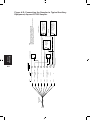
&211(&7,1* 7+( 6$03/(5 72 7<3,&$/ $8;,/,$5< (48,30(17 6 6 6 6$03/(56
6$03/( $&48,5(' 23 $
127( 5(027( &21752/ ,3
9
<(//2:
*5((1
%/8(
:+,7( 6$03/(5 :$51,1* 23 $ 127(6 %52:1
6$03/(5 :$51,1* 23% 127(6
9,2/(7
$8;,/,$5< (48,30(17
&211(&7,216
)81&7,21
:,5(
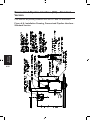
Figure 4.F: Connecting the Sampler to Typical Auxiliary
Equipment, Aquacell S200 Sampler
4.11
Aquacell S300 Series Samplers
First remove all packing material from the Sampler and it’s ancillaries
except for the wooden palette on which the Sampler stands. Note:
The Sampler’s Lower Compartment is used to transport the Sample
Collection Vessel, ancillaries etc.
Figure 4.G: Installation Drawing, S300 Series Sampler - Top, Left
Side and Front Views
All dimensions are in mm.
PREPARING
THE SITE
4.12
Figure 4.H: Installation Drawing, S300 Series Sampler - Right
Side and Rear Views
PREPARING
THE SITE
All dimensions are in mm.
4.13
Sampler Location
A flat, horizontal mounting base (typically a 100mm thick concrete
pad) should be provided for the Sampler, preferably with a standing
area in front and service access to the rear.
Gravity Drain (Condensate) Installation (if required)
Construct the drain from 21.5mm O/D plastic pipe.
It is important when configuring the drain to avoid the possibility of
water being removed from the trap by siphon action.
The Sampler is provided with a 21.5mm O/D stub pipe at the bottom
rear of the Sampler Cabinet. The drain-pipe is joined to the stub pipe
using a suitable fitting.
(Optional) Condensate Evaporator Tray Installation
PREPARING
THE SITE
4.14
Attach the 4 Thermal Isolation Springs to the feet of the tray. The
springs are quite a tight force fit. The tray gets too hot to touch and
the Thermal Isolation Springs serve to isolate the hot under-surface of
the tray from the floor that it stands on.
The tray stands on the Mounting Base at the rear of the Sampler
suitably positioned beneath the Condensate Drain Outlet Stub Pipe.
In this way condensate is deposited into the tray and evaporated
off into the atmosphere. The Condensate Evaporator Tray is only
energised when the Sampler’s Refrigeration Unit is operating (to
minimise electricity consumption).
Gravity Drain (Wastewater) Installation (if required)
Construct the drain from 56mm O/D plastic pipe and terminate it in
the P-Trap supplied with the Sampler (attach the drainpipe to the
output of the P-Trap i.e. the lower connection point).
It is important when configuring the drain to avoid the possibility of
water being removed from the trap by siphon action.
The Sampler is provided with a 56mm stub pipe at the bottom rear of
the Sampler Cabinet. The P-Trap is attached to the Sampler at this
point.
Gravity Drain for Self
Emptying Bottler (if required)
Samplers specified with a 2 x 4.5
litre Self-emptying Integral Bottler are
supplied with a Wastewater Drain. The
bottler drain outlet and the Wastewater
Drain outlet are connected to a P-Trap
using the compression fittings supplied
Electrical Power Supply
Installation
Auxiliary Equipment Installation
Equipment can be mounted separately from the Sampler and
connected to it via the “Optional Connections” Terminal Block
mounted in the terminal enclosure at the rear of the Sampler, by
specifying the (Optional) Ancillary Signal Connection.
Alternatively equipment can be mounted integrally to the Sampler
by specifying either the (Optional) Auxiliary Equipment Plate, or the
(Optional) Auxiliary Equipment Enclosure.
See page 4.18 Connecting the Sampler to Typical Auxiliary Equipment,
Aquacell S300 Series Samplers for application information.
(Optional) Ancillary Signal Connection
Auxiliary Equipment should, if possible, be positioned adjacent to
the Sampler, such that the cable connecting between the Samplers
Optional Connections Terminal Block, and the Auxiliary Equipment
doesn’t exceed 1.5 metres.
PREPARING
THE SITE
A suitable electrical supply should be provided for the Sampler - see
TECHNICAL SPECIFICATION Page page 8.7, which is terminated in a
switched fused isolator, fused according to the VA rating indicated on
the Samplers Rating Label (beneath the cable glands on the lower
rear panel of the Sampler Cabinet). The isolator should be mounted
conveniently close to the Sampler’s Power Input Cable Gland
positioned at the rear of the Sampler.
4.15
Cables to / from the Auxiliary Equipment may need to be terminated
in one or more Signal Isolators (Not supplied by Aquamatic) mounted
adjacent to the Sampler. The isolators should be connected to the
Sampler via the Samplers Ancillary Signals Cable.
Isolators are necessary to protect the Samplers inputs / outputs from
damaging electrical transients, which are sometimes induced in long
cables.
(Optional) Auxiliary Equipment Mounting Plate
Caution: All equipment attached to the mounting plate (including
junction boxes, terminal blocks etc.) must be suitably environmentally
protected.
See page 4.19, Wiring Details - (Optional) Auxiliary Equipment Mounting
Plate / (Optional) Auxiliary Equipment Enclosure
The Auxiliary Equipment Mounting Plate is made from stainless steel
so any cutting tools used in the preparation of the plate must take this
into account
PREPARING
THE SITE
4.16
Drill the mounting plate and attach the Auxiliary equipment as
required.
Terminate the Mains Cable from the Auxiliary Equipment in the
Auxiliary Power Connector provided
Terminate the Ancillary Signal Cable provided, in the Auxiliary
Equipment as appropriate.
The Equipment should have 2 strain relieved flying leads coming from
it, cut to a suitable length to connect to the mating connectors on the
left hand side of the Sampler
(Optional) Auxiliary Equipment Enclosure
See page 4.19 Wiring Details - (Optional) Auxiliary Equipment Mounting
Plate / (Optional) Auxiliary Equipment Enclosure
Open the enclosure using the key provided and remove the mounting
plate
Drill the mounting plate and attach the Auxiliary equipment as
required.
Replace the Mounting Plate in the enclosure
Thread the mains cable out through the top cable gland on the lefthand side of the enclosure and terminate it in the Auxiliary Power
Connector provided.
Thread the Auxiliary Signals Cable in through the bottom cable gland
on the left-hand side of the enclosure and couple it to the auxiliary
equipment as required.
PREPARING
THE SITE
The Auxiliary Equipment Enclosure should have 2 strain relieved
flying leads coming from it, cut to a suitable length to connect to the
mating connectors on the left-hand side of the Sampler.
4.17
6$03/(5 ,13876 2873876
63$5( &211(&7,216 /,1. )520 237,21$/
&211(&7,216 7(50,1$/ %/2&. 72 $1&,//$5<
6,*1$/6 5(3($7(5 &2111(&7,21 21 7+( /()7
+$1' 6,'( 3$1(/ 2) 7+( &$%,1(7 127( 9
)/2: ,3
6$03/( $&48,5(' 23 $
127( 5(027( &21752/
,3
9
6$03/(5 :$51,1* 23 $
127(6 6$03/( $&48,5(' 23 %
127( 6$03/(5 :$51,1* 23%
127(6 $8; $8; $8; $8; '$7$ /2**(5 (7&
$/$50 $1181&,$725 (7&
5(/$< &217$&7
1250$//< 23(1
92/7 )5((
5(027( &21752/ 3803 21 2)) (7&
)/2:0(7(5 :,7+ )/2:
5$7( $1$/2*8( 6,*1$/
,62/$7(' P$
)/2:0(7(5 :,7+ ,17(*5$7('
)/2: ,038/6( 6,*1$/
1250$//< 23(1 92/7 )5(( 5(/$< &217$&7
)/2:0(7(5 $
)/2:0(7(5 % 127(
127(6
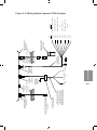
6833/,(' :+(1 $1&,//$5< 6,*1$/ &211(&7,21 ,6 63(&,),('
$/7(51$7,9( )/2:0(7(5 % &211(&7,216 6+2:1 '277('
2873876 $5( 1250$//< 23(1 92/7 )5(( 5(/$< &217$&76 5$7(' $7 9 '& $
&217$&76 $5( &/26(' :+(1 7+( 6<67(0 ,6 +($/7+<
:+(1 (,7+(5 7+( $8;,/,$5< (48,30(17 02817,1* 3/$7( 25 7+( $8;,/,$5< (48,30(17 (1&/2685( ,6 63(&,),('
&211(&7,1* 7+( 6$03/(5 72 7<3,&$/ $8;,/,$5< (48,30(17 6 6(5,(6
237,21$/
&211(&7,216
7(50,1$/ %/2&.
127( PREPARING
THE SITE
4.18
)81&7,21
Figure 4.I: Connecting the Sampler to Typical Auxiliary
Equipment, Aquacell S300 Series Samplers
$1&,//$5< 6,*1$/6
5(3($7(5 &$%/(
6$03/( $&48,5('
23 $
)/2: ,3
9
*5((1
5('
%/$&.
%/8(
<(//2:
9
:+,7(
5(027( &21752/
,3
6$03/( $&48,5('
23 %
6$03/(5 0$/)81&7,21
23 $
9,2/(7
%52:1
$8; 6$03/(5 0$/)81&7,21
23%
25$1*(
$8; $8; 3,1.
$8; 785482,6(
)81&7,21
:,5(
*5(<
'$1*(5 7+( $8;,/,$5< (48,30(17 32:(5
&$%/( &$55,(6 0$,16 92/7$*( :+(1
&211(&7(' 72 7+( $8;,/,$5< 32:(5
&211(&725 21 7+( 6,'( 2) 7+( 6$03/(5
(1685( 7+$7 ,7 ,6 6$)(/< 7(50,1$7(' %()25(
&211(&7,1*
1
6$03/(5 &211(&7,216 &211(&7 72
$8;,/,$5< (48,30(17 $6 $335235,$7(
63$5( &211(&7,216 /,1. )520 237,21$/
&211(&7,216 7(50,1$/ %/2&. 72 $1&,//$5<
6,*1$/6 5(3($7(5 &2111(&7,21 &211(&7 72
$8;,/,$5< (48,30(17 $6 $335235,$7(
PREPARING
THE SITE
:,5,1* '(7$,/6 237,21$/ $8;,/,$5< (48,30(17 02817,1* 3/$7( 237,21$/ $8;,/,$5< (48,30(17 (1&/2685(
/()7 +$1' 6,'( 3$1(/ 2) &$%,1(7
$1&,//$5< 6,*1$/6
5(3($7(5&211(&725
%27720
$8;,/,$5< 32:(5 &211(&725 3/8*
6833/,(' 81:,5('
$8;,/,$5< 32:(5
&211(&725 62&.(7 723
127( $8;,/,$5< (48,30(17 (1&/2685(
7+( 32:(5 $1' 6,*1$/ &$%/(6 3$66 7+528*+ &$%/(
*/$1'6 ,1 7+( (48,30(17 (1&/2685( :$//
:,5,1* $8;,/,$5< (48,30(17 32:(5 &211(&725
72 $8;,/,$5< (48,30(17 32:(5 &$%/(
',60$17/( 7+( &211(&725 86,1* 7+( &$67(//$7('
.(< 21 7+( 723 2) 7+( '867 &$3 ),77(' 72 7+( 833(5 32/( &211(&725 21 7+( 6,'( 2) 7+( &$%,1(7
7+5($' 7+( &211(&725 6+(// 2172 7+( 32:(5
&$%/(
&211(&7 :,5(6 )520 7+( $8;,/,$5< (48,30(17
6833/< &$%/( 72 7+( 32:(5 &211(&725 $6 )2//2:6
/,9( 7(50,1$/ /
($57+ 7(50,1$/ (
(
1(875$/ 7(50,1$/ 1
5($6(0%/( 7+( &211(&725
/
7,*+7(1 7+( 675$,1 5(/,() */$1'
187 $7 7+( 5($5 2) 7+( &211(&725 6+(//
Figure 4.J: Wiring Details - (Optional) Auxiliary Equipment
Mounting Plate/(Optional) Auxiliary Equipment Enclosure
4.19
Pressurised Pipeline Interface (PPI) - Standard
Version
First remove all packing material from the PPI and it’s ancillaries.
Figure 4.K: Installation Drawing, Pressurised Pipeline Interface Standard Version
PREPARING
THE SITE
4.20
PPI Location
A wall or similar flat surface is required, on which to mount the PPI
cabinet. The PPI should be positioned according to the Installation
Drawing above
Gravity Drain Installation
Construct the drain from 56mm O/D plastic pipe. The drain should be
coupled to the PPI Drain Outlet and should lead to a suitable disposal
point. It may be possible to couple the PPI drain into the Wastewater
Drain (if one is fitted), however care must be taken in configuring the
drain to avoid any backflushing issues
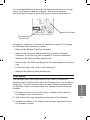
Installing the Pressure Tapping
Electrical Power Supply Installation
A suitable electrical supply should be provided for the PPI - see
TECHNICAL SPECIFICATION, (page 8.6) which is terminated in a
switched fused isolator, fused as indicated on the PPI Rating Label.
The isolator should be mounted conveniently close to the PPI Power
Input Cable Gland.
PREPARING
THE SITE
A suitable tapping point should be made and fitted with a hand
operated Isolation Valve. The Pressure Tapping should be terminated
in a 1/2" BSP femail fitting, to which the PPI intake Hose can be
connected.
4.21
Pressurised Pipeline Interface (PPI) - S300
Version
Figure 4.L: Installation Drawing, Pressurised Pipeline Interface S300 Version
PREPARING
THE SITE
4.22
Gravity Drain Installation
Construct the drain from 56mm O/D plastic pipe. The drain should be
coupled to the PPI Drain Outlet and should lead to a suitable disposal
point. It may be possible to couple the PPI drain into the Wastewater
Drain (if one is fitted), however care must be taken in configuring the
drain to avoid any backflushing issues.
Installing the Pressure Tapping
PREPARING
THE SITE
A suitable tapping point should be made and fitted with a hand
operated Isolation Valve. The Pressure Tapping should be terminated
in a 1/2" BSP femail fitting, to which the PPI intake Hose can be
connected.
4.23
PREPARING
THE SITE
4.24
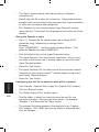
5
INSTALLATION
Aquacell S50 Sampler
See page 4.1, Fig. 4.A, Installation Drawing, S50 Sampler.
Sampler
1. Drill the 2 mounting holes (using an 8mm masonry drill, if using
the fixing bolts supplied) in the wall (or other appropriate vertical
surface), and install the masonry bolts (or other appropriate
fixings) at the designated points.
2. Install the Back-up Battery (if applicable) – See (Optional) Back-up
Battery Installation (page 5.18).
4. Loosen the 2 fixing bolts slightly, in order to accommodate the
keyhole cut-outs in the Sampler Module’s mounting bracket. Hang
the Sampler Module / bracket on the fixing bolts and tighten them
up to secure the Sampler Module on its mount.
INSTALLATION
3. Take note of the position and orientation of (optional) electrical
connectors fitted to the bottom rear Connection Panel (if any are
fitted), as this will be difficult to do when the sampler is in place
and it is required to connect the corresponding cables.
5. Connect the Mains cable to the switched, fused isolator[1]. DO
NOT SWITCH THE POWER ON AT THIS POINT.
5.1
6. Connect any other cables as appropriate to the Sampler Module –
See Electrical Connections to the Sampler Module (page 5.2).
7. Install the Intake Hose – See Intake Hose Installation (page 5.14).
[1] PPI Standard Version - Do not connect the Sampler Module to
the switched, fused Isolator. The power connection is routed via the
PPI
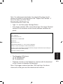
Sample Collection Vessel (SCV)
1. Place the SCV (Single Container or Bottler as appropriate)
beneath the sampler outlet (Pinch Valve Tube).
2. Place the Pinch Valve Tube in the top opening of the Container
/ Bottler. The tube should engage the Container / Bottler to a
nominal depth of 60mm.
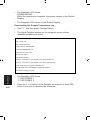
Electrical Connections to the Sampler Module
See Fig. 5.A: Wiring Details, Aquacell S50 Sampler.
Electrical connections to the Sampler Module are made principally via
the connection panel at the bottom rear of the module.
There is an (optional) USB connection on the front panel of the
Sampler Module This is intended for operator use as required, to
download the Sampler’s data logger and would not be involved at the
installation stage.
The connection panel comprises a flying lead coming from a cable
gland in the middle of the panel. This is the Mains Cable. In addition
there are 4 (optional) waterproof connectors. (See Wiring Details).
INSTALLATION
5.2
When connecting a cable to a connector, first remove the connector
sealing cap. Care should be exercised to correctly orientate the
connectors, before applying any force, to mate one with the other.
Having mated the connectors correctly, the retaining cover should
be screwed in place, taking care to avoid cross-threading. If difficulty
is experienced in engaging the threads, rotate the retaining cover in
reverse until a click is heard. Then rotate the cover in a clockwise
direction to secure the connector.
237,21$/ 7(03(5$785( 352%( 3/$&( ,1 6&9 127 )25 86( :,7+
%277/(56
237,21$/ 7(03(5$785(
352%( &211(&7,21
0$,16
&211(&7,21
)/<,1* /($'
/,9(
%52:1
INSTALLATION
1(875$/
($57+
)81&7,21
:,5(
237,21$/
$1&,//$5<
6,*1$/
&$%/(
237,21$/
%277/(5
&211(&7,21
237,21$/
'(7$&+$%/(
%277/(5
),* D :,5,1* '(7$,/6 6 6$03/(5
%/8(
237,21$/
$1&,//$5<
6,*1$/
&211(&7,21
*5((1 <(//2:
0$,16 &$%/( 127( 33,
9(56,21 7+,6 &$%/( ,6
7(50,1$7(' ,1 $ %8&&$1((5
&211(&725
237,21$/ 33,
&211(&7,21
%27720 5($5 )$&( 2)
6$03/(5 02'8/(
)/2: ,3
9
5('
6$03/( $&48,5(' 23 $
<(//2:
%/$&.
5(027( &21752/ ,3
*5((1
9
6$03/( $&48,5(' 23 %
6$03/(5 0$/)81&7,21 23 $
:+,7(
%/8(
6$03/(5 0$/)81&7,21 23%
)81&7,21
%52:1
:,5(
9,2/(7
Figure 5.A: Wiring Details, Aquacell S50 Sampler
5.3
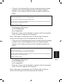
Aquacell S100 Sampler
See page 4.5, Fig. 4.C, Installation Drawing, S100 Sampler.
Sampler
1. Drill the 4 mounting holes (using an 8mm masonry drill, if using
the fixing bolts supplied) in the wall (or other appropriate vertical
surface), and install the masonry bolts (or other appropriate
fixings) at the designated points.
2. Attach the Wall Mounting Plate to the mounting surface
3. Install the Back-up Battery (if applicable) – See (Optional) Back-up
Battery Installation (page 5.18).
4. Take note of the position and orientation of electrical connector(s)
fitted to the bottom rear Connection Panel, as this will be difficult
to do when the sampler is in place and it is required to connect the
corresponding cables.
5. Loosen the 2 wing nuts on the Wall Mounting Plate and hang the
Sampler on the Mounting Studs. Hand -tighten the wing nuts to
secure the sampler firmly in place.
6. Connect the Mains cable to the switched, fused isolator[1]. DO
NOT SWITCH THE POWER ON AT THIS POINT.
INSTALLATION
7. Connect any other cables as appropriate to the Sampler Module –
See Electrical Connections to the Sampler Module (page 5.5).
5.4
Sample Collection Vessel (SCV)
8. Install the Intake Hose – See Intake Hose Installation (page 5.14).
1. Place the SCV (Single Container or Bottler as appropriate)
beneath the sampler outlet (Pinch Valve Tube).
[1] PPI Standard Version - Do not connect the Sampler Module to
the switched, fused Isolator. The power connection is routed via the
PPI
2. Place the Pinch Valve Tube in the top opening of the Container
/ Bottler. The tube should engage the Container / Bottler to a
nominal depth of 60mm.
Electrical Connections to the Sampler Module
See Figure 5B: Wiring Details, Aquacell S100 Sampler (page 5.6).
Electrical connections to the Sampler Module are made principally via
the connection panel at the bottom rear of the module.
There is an (optional) USB connection on the front panel of the
Sampler Module This is intended for operator use as required, to
download the Sampler’s data logger and would not be involved at the
installation stage.
When connecting a cable to a connector, first remove the connector
sealing cap. Care should be exercised to correctly orientate the
connectors, before applying any force, to mate one with the other.
Having mated the connectors correctly, the retaining cover should be
screwed in place, taking care to avoid cross-threading. If difficulty
is experienced in engaging the threads, rotate the retaining cover in
reverse until a click is heard. Then rotate the cover in a clockwise
direction to secure the connector.
INSTALLATION
The connection panel comprises a Mains connection and 4 (optional)
additional connections. The connectors are all waterproof (See
Wiring Details).
5.5
237,21$/ 7(03(5$785( 6(1625
3/$&( ,1 6&9 127 )25 86( :,7+
%277/(56
0$,16
&211(&7,21
1(875$/
($57+
/,9(
)81&7,21
:,5(
237,21$/
$1&,//$5<
6,*1$/
&$%/(
237,21$/
%277/(5
&211(&7,21
),* E :,5,1* '(7$,/6 6 6$03/(5
%/8(
*5((1 <(//2:
237,21$/
$1&,//$5<
6,*1$/
&211(&7,21
%52:1
0$,16 &$%/( 127( 33, 9(56,21 7+,6
&$%/( ,6 (;&/8'('
237,21$/ 33,
&211(&7,21
INSTALLATION
5.6
237,21$/ 7(03(5$785(
352%( &211(&7,21
237,21$/
'(7$&+$%/(
%277/(5
%27720 5($5 )$&( 2)
6$03/(5 02'8/(
)/2: ,3
9
%/$&.
6$03/( $&48,5(' 23 $
<(//2:
5('
5(027( &21752/ ,3
*5((1
9
:+,7(
%/8(
6$03/( $&48,5(' 23 %
6$03/(5 0$/)81&7,21 23 $
%52:1
)81&7,21
6$03/(5 0$/)81&7,21 23%
:,5(
9,2/(7
Figure 5.B: Wiring Details, Aquacell S100 Sampler
Aquacell S200 Series Samplers
See Fig. 4.E, Installation Drawing, S200 Sampler (page 4.9).
Sampler
1. Move the Sampler on its wooden pallet, to a position close to the
prepared base.
2. Remove the transit bolts attaching the Sampler to its pallet.
3. Carefully remove the Sampler from its pallet and position it on its
prepared base.
4. Install the Back-up Battery (if applicable) – See (Optional) Back-up
Battery Installation (page 5.18).
5. Connect the Mains cable from the Junction Box on the Sampler
bracket to the switched, fused isolator[1]. DO NOT SWITCH THE
POWER ON AT THIS POINT.
6. Connect any other cables as appropriate to the Sampler Module –
See Electrical Connections to the Sampler Module (page 5.7).
7. Install the Intake Hose – See Intake Hose Installation (page 5.14).
1. Place the SCV (Single Container or Bottler as appropriate) in the
Lower Compartment beneath the sampler outlet (Pinch Valve
Tube).
2. Place the Pinch Valve Tube in the top opening of the Container
/ Bottler. The tube should engage the Container / Bottler to a
nominal depth of 60mm.
3. If the SCV is a Bottler, connect it to the Bottler Connection (The
cable suspended from the top of the Lower Compartment)
[1] PPI Standard Version - Do not connect the Sampler Module to
the switched, fused Isolator. The power connection is routed via the
PPI
INSTALLATION
Sample Collection Vessel (SCV)
5.7
Electrical Connections to the Sampler Module
See Fig. 5.C: Wiring Details, Aquacell S200 Sampler (page 5.9).
Electrical connections to the Sampler Module are made principally
via the connection panel at the bottom rear of the module. Only the
(optional) Ancillary Signal Cable needs to be fitted during installation,
as the other cable(s) are pre-connected.
The (optional) Bottler connection is a waterproof in-line connector
suspended from the top of the Lower Compartment.
There is an (optional) USB connection on the front panel of the
Sampler Module This is intended for operator use as required, to
download the Sampler’s data logger and would not be involved at the
installation stage.
The connection panel comprises a Mains connection and 4 (optional)
additional connections. The connectors are all waterproof (See
Wiring Details).
INSTALLATION
5.8
When connecting a cable to a connector, first remove the connector
sealing cap. Care should be exercised to correctly orientate the
connectors, before applying any force, to mate one with the other.
Having mated the connectors correctly, the retaining cover should be
screwed in place, taking care to avoid cross-threading. If difficulty
is experienced in engaging the threads, rotate the retaining cover in
reverse until a click is heard. Then rotate the cover in a clockwise
direction to secure the connector.
0$,16
&211(&7,21
35(
&211(&7('
/,9(
%52:1
)81&7,21
:,5(
237,21$/
$1&,//$5< 6,*1$/
&$%/( 6(( 127(
237,21$/
%277/(5
&211(&7,21
35(
&211(&7('
),* F :,5,1* '(7$,/6 6 6$03/(5
1(875$/
INSTALLATION
($57+
%/8(
237,21$/
$1&,//$5<
6,*1$/
&211(&7,21
*5((1 <(//2:
)5,'*( 0$,16
&$%/( 35(
&211(&7('
/2:(5 &203$570(17
723
237,21$/ 33,
&211(&7,21
0$,16 &$%/( &211(&7 72
6:,7&+(' )86(' ,62/$725 127( 33, 9(56,21 7+,6 &$%/( ,6
7(50,1$7(' ,1 $ %8&&$1((5
&211(&725 :+,&+ &211(&76 72
7+( 33, 6$03/(5 32:(5 &$%/(
-81&7,21 %2; $77$&+('
72 6$03/(5 %5$&.(7
237,21$/ 7(03(5$785( 6(1625
3/$&( ,1 6&9 127 )25 86( :,7+
%277/(56
237,21$/ 7(03(5$785(
352%( &211(&7,21 35(
&211(&7('
%27720 5($5 )$&( 2)
6$03/(5 02'8/(
237,21$/ '(7$&+$%/(
%277/(5 ,1 /2:(5
&203$570(17
/2:(5 &203$570(17
723
)/2: ,3
9
5('
%/$&.
6$03/( $&48,5(' 23 $
<(//2:
9
5(027( &21752/ ,3
*5((1
%/8(
6$03/(5 0$/)81&7,21 23 $
6$03/( $&48,5(' 23 %
:+,7(
%52:1
)81&7,21
6$03/(5 0$/)81&7,21 23%
:,5(
9,2/(7
Figure 5.C: Wiring Details, Aquacell S200 Sampler
5.9
Aquacell S300 Series Samplers
See Figure: 4.G Installation Diagram S300 Series Sampler (page 4.12)
Sampler
1. Move the Sampler on its wooden pallet to a position close to the
prepared base
2. Remove the transit bolts attaching the Sampler to its pallet.
3. Carefully remove the Sampler from its pallet and position it on the
prepared base.
4. Fasten the Sampler down on the base using suitable fixing screws
in the four 13mm fixing holes in the cabinet base flanges.
5. Attach the 2 Air Cowls using the fixing screws provided. (S310H
and S320H models only)
6. Connect up the gravity drain to the Condensate Drain outlet /
Wastewater Drain outlet (if applicable).
7. Ensure the backup battery switch is set to the 'disconnected'
position - see (Optional) Back-up Battery Installation (page 5.18)
INSTALLATION
5.10
8. Remove the Cover Plate on the Samplers Upper Rear Panel
by removing the 4 fixing screws. This exposes the Samplers
electrical terminals.
9. Install electrical connections - See Figure 5.D: Wiring Details,
Aquacell S300 Series Samplers (page 5.12). DO NOT SWITCH THE
POWER ON AT THIS POINT.
10.Replace the cover plate.
11.Install the Intake Hose – See Intake Hose Installation (page 5.14).
Sample Collection Vessel (SCV)
Single Containers / Detachable Bottlers
12.Place the SCV on the Tray in the Lower Compartment beneath the
sample outlet (pinch valve tube).
13.Place the Pinch Valve Tube in the top opening of the Container /
Bottler. The tube should engage the SCV to a nominal depth of
60mm
14.If the SCV is a bottler, connect its cable to the Bottler Connection
(the cable suspended from the top of the lower compartment of
the Sampler Cabinet)
Integral Bottlers
Position Bottles/Bottle Carrier on the SCV tray as determined by the
plastic location pegs.
(Optional) Auxiliary Equipment Mounting Plate
Attach the fully assembled / wired Equipment Mounting Plate to the
4 fixing points on the left-hand side of the Sampler using the fixing
screws provided.
Connect the Ancillary Signal Cable to the 12-pole connector on the
side of the Sampler.
Connect the Mains Supply Cable to the 3-pole connector on the side
of the Sampler.
Use the key provided to open the Enclosure door and gain access
to the 4 fixing holes. Attach the fully assembled / wired Equipment
Enclosure to the 4 fixing points on the left-hand side of the Sampler
using the fixing screws provided.
Connect the Ancillary Signal Cable to the 12-pole connector on the
side of the Sampler.
Connect the Mains Supply Cable to the 3-pole connector on the side
of the Sampler.
INSTALLATION
(Optional) Auxiliary Equipment Enclosure
5.11
INSTALLATION
5.12
237,21$/ $1&,//$5<
6,*1$/6 &$%/( */$1'
9
)/2: ,3
6$03/( $&48,5('
23 $ 127( 5(027( &21752/
,3
9
6$03/(5 0$/)81&7,21
23 $ 127(6 6$03/( $&48,5('
23 % 127( 6$03/(5 0$/)81&7,21
23% 127(6 $8; $8; $8; $8; 127( 237,21$/ '(7$&+$%/( %277/(56
&211(&7 7+( %277/(5
6 ,17(*5$/ &$%/( 72
7+( 237,21$/ %277/(5 &211(&7,21 &$%/(
6863(1'(' )520 7+( ,16,'( 723 2) 7+(
&$%,1(7 /2:(5 &203$570(17
),* G :,5,1* '(7$,/6 6 6(5,(6 6$03/(56 6$03/(56
237,21$/ 6,*1$/ 7(50,1$/ %/2&.
&$%/( */$1' 3/$7( 21 5($5
2) 6$03/(5 &$%,1(7
32:(5 ,1387 &$%/(
*/$1'
0$,16 ,1387
/ ( 1
$
32:(5 6833/<
)86( $
237,21$/ &211(&7,216
32:(5 ,1387 7(50,1$/ %/2&.
7(50,1$/ $3(5785( ,1 833(5 5($5 3$1(/ 2) 6$03/(5 &$%,1(7
5(029( &29(5 3/$7( )25 $&&(66
Figure 5.D: Wiring Details, Aquacell S300 Series Samplers
Pressurised Pipeline Interface - Standard Version
See Figure 4.K, Installation Drawing, Pressurised Pipeline Interface Standard Version (page 4.20).
1. Drill the 4 mounting holes (using an 8mm masonry drill, if using
the fixing bolts supplied) in the wall (or other appropriate vertical
surface), and install the masonry bolts (or other appropriate
fixings) at the designated points.
2. Attach the PPI Housing to the mounting surface
3. Connect PPI Main Power Cable to the switched, fused isolator.
DO NOT SWITCH THE POWER ON AT THIS POINT.
4. Connect the PPI, Sampler Power Cable to the Power Cable
connector (S50 and S200) or the Mains connector on the Sampler
Module (S100) as appropriate.
5. Connect the PPI Signal Cable to the PPI connector on the
Sampler Module
6. Install the Intake Hose – See Intake Hose Installation (page 5.14).
See Figure 4.L, Installation Drawing, Pressurised Pipeline Interface S300 Version (page 4.22).
1. Install the Intake Hose – See Intake Hose Installation (page 5.14).
INSTALLATION
Pressurised Pipeline Interface - S300 Version
5.13
Intake Hose Installation
Non Pressurised Sampling Points
The Sampler is supplied with a standard 10 metre (S50 - 5 metre)
long Intake Hose, which has an Intake Filter fitted at the Sampling
Point End. The hose connects between the Sampling Point and the
Sampler Module.
Installation Procedure:
a. Install a suitable Intake Hose Support for the Sampling Point end
of the Intake Hose. The illustration below shows the (optional)
Intake Hose Support Bracket and is an example of how the hose
is meant to be supported, although not suited to every application.
INSTALLATION
5.14
b. Attach one of the two Intake Hose Anchors supplied, to the
hose at a point such that, when it engages with the Intake Hose
Support, the Intake Filter is suspended in the body of wastewater
from which samples are to be extracted.
Note: The Intake Hose Anchor comprises a short silicone rubber
split tube which wraps around the Intake Hose and a plastic tube
clip which is tightened around the silicone rubber, using pliers. See
illustration below:
c. Suspend the Intake Hose in the flow by engaging the Intake Hose
Anchor with the Intake Hose Support.
d. Run the Intake Hose along its designated path up to the Sampler
Intake.
e. Attach the upper end of the Intake Hose to the Sample Intake:
S50 Sampler
Note: Strain relief for the upper end of the Intake Hose is not provided
with the S50 and in applications where this is judged to be necessary;
a suitable Strain Relief Bracket should be installed.
In many applications where there is just a short lift and the flow is not
vigorous, strain relief of the upper end of the Intake Hose may not be
necessary.
If strain relief is required for the upper end of the Intake Hose,
proceed as follows:
a. Attach a second Intake Hose Anchor to the upper end of the
Intake Hose at a point such that, when it engages with the Strain
Relief Bracket, it suspends in its intended manner.
c. Cut the Intake Hose to length so that the free end is able to
engage with the Intake Pipe on the Sampler Module (Allow about
20mm of hose to engage with the Intake Pipe).
d. Place the Intake Hose Clip over the free end of the Intake Hose
and soften the end of the hose by the application of heat using a
hot air gun.
e. Push the hose onto the Intake Pipe so that approximately 20mm
is engaged and secure in place by tightening the Intake Hose Clip,
using pliers.
Note: If strain relief is not required for the upper end of the Intake
Hose, proceed from c) above.
S100 and S200 Samplers
Attach the Strain Relief Bracket supplied to the side of the Sampler
Module using the 2 M4 screws/washers.
INSTALLATION
b. Suspend the Intake Hose by engaging the Intake Hose Anchor
with the Strain Relief Bracket.
5.15
a. Attach a second Intake Hose Anchor to the upper end of the
Intake Hose at a point such that, when it engages with the Strain
Relief Bracket, it suspends in its intended manner.
b. Suspend the Intake Hose by engaging the Intake Hose Anchor
with the Strain Relief Bracket
c. Cut the Intake Hose to length so that it is able to engage with the
Intake Pipe on the Sampler Module (Allow about 20mm of hose to
engage with the Intake Pipe).
d. Place the Intake Hose Clip over the upper end of the Intake Hose
and soften the end of the hose by the application of heat using a
hot air gun
e. Push the hose onto the Intake Pipe so that approximately 20mm is
engaged and secure in place by tightening the Intake Hose Clip.
S300 Series Samplers
Note: Strain relief for the upper end of the Intake Hose is provided by
a plastic gland in the Right Hand Side Panel of the Sampler Cabinet.
a. Thread the upper end of the Intake Hose through the plastic gland
in the Right Hand Side Panel of the Sampler Cabinet
INSTALLATION
5.16
b. Attach a second Intake Hose Anchor to the upper end of the
Intake Hose at a point such that, when it engages with the plastic
gland in the Right Hand Side Panel of the Sampler Cabinet, it
suspends in its intended manner.
c. Suspend the Intake Hose by engaging the Intake Hose Anchor
with the plastic gland in the Right Hand Side Panel of the Sampler
Cabinet
d. Cut the Intake Hose to length so that it is able to engage with the
Intake Pipe on the Sampler Module (Allow about 20mm of hose to
engage with the Intake Pipe).
e. Place the Intake Hose Clip over the upper end of the Intake Hose
and soften the end of the hose by the application of heat using a
hot air gun
f. Push the hose onto the Intake Pipe so that approximately 20mm is
engaged and secure in place by tightening the Intake Hose Clip.
Pressurised Sampling Points - Samplers
incorporating The Pressurised Pipeline Interface (PPI)
The Sampler is supplied with 2 intake hoses; a standard 10 Metre
length Intake Hose, with a fixing Flange fitted to one end, to connect
from the Sampling Point, to the PPI, and a Short Hose to connect
from the PPI to the Sampler Module.
Installation Procedure:
1. Couple the 1/2" BSP Tapered Male Fitting at the Sampling Point
End of the 10 Metre Intake Hose to the pre-installed Pipeline
Tapping Point (Use PTFE tape to seal the joint).
2. Run the Intake Hose along its designated path to the Pressurised
Pipeline Interface Intake. (The 16mm Hose Tail Fitting, protruding
from the right hand side of the Pressurised Pipeline Interface
Enclosure)
4. Place the Intake Hose Clip supplied over the PPI end of the Intake
Hose and soften the end of the hose by the application of heat
using a hot air gun
5. Push the hose onto the PPI Intake Hose Connector so that
approximately 30mm is engaged and secure in place by tightening
the Intake Hose Clip, using a screwdriver.
6. Place the other Intake Hose Clip supplied over the PPI end of the
Short Hose (the plain end) and soften the end of the hose by the
application of heat using a hot air gun.
7. Push the hose onto the PPI Outlet Hose Connector so that
approximately 30mm is engaged and secure in place by tightening
the Inlet Hose Clip, using a screwdriver.
8. Connect the other end of the Short Hose to the Intake Pipe on the
Sampler Module.
Note: S300 Series Samplers – The Short Hose is pre-installed, so
ignore 6. onwards, above.
INSTALLATION
3. Cut the Intake Hose to length so that it is able to engage with the
Pressurised Pipeline Interface Intake (Allow about 30mm of hose
to engage with the 16mm Hose Tail Fitting).
5.17
(Optional) Back-up Battery Installation
S50 / S200 Samplers
Place the battery in the battery cavity at the rear of the Sampler
Module and secure it in place with the rubber cord, by stretching it
over the battery / battery connecting cable and attaching it to the
metal clip at the top of the battery cavity. Do not connect the battery
to the Sampler Module at this point [1].
S100 Sampler
1. Release the toggle latch securing the hinged Battery Cover, at
the rear of the Sampler Module and open the Battery Cover, to
reveal the battery cavity.
2. Place the battery in the battery cavity and secure it in place
with the rubber cord, by stretching it over the battery / battery
connecting cable and attaching it to the metal clip at the top of
the battery cavity. Do not connect the battery to the Sampler
Module at this point [1].
3. Close the Battery Cover and secure the toggle latch.
S300 Series Samplers
INSTALLATION
The Back-up Battery is pre-installed in S300 Series Samplers
and has a rocker switch mounted on the Sampler Panel, used to
disconnect or connect the battery as required. This switch should
be set to the “Disconnected” position as the Back-up Battery should
not be connected at this point [1].
5.18
[1] IMPORTANT: The Back-up Battery, should not be connected to
the Sampler and left for an extended period (more than 24hrs) before
the system is commissioned, as it may become fully discharged. If
this happens, battery / Sampler damage could result.
6
OPERATION
Definitions
AQUACELL SAMPLER
The basic Aquacell Air Pump Vacuum
Sampler.
SAMPLING POINT
The precise position within a sampling
location from which samples are taken.
SAMPLING CYCLE
The sequence of operations the Sampler
carries out in order to extract a shot of
the liquid to be sampled.
SHOT
An aliquot of liquid extracted from the
sampling point by a single operation of
the sampling cycle.
SAMPLE
A shot or number of shots extracted in
immediate succession and deposited
into a single collection vessel.
GROUP SAMPLE
A series of shots extracted in immediate
succession and split between a
predetermined group of collection
vessels. See Programming Procedure,
SYSBOT04 (page 6.28).
COMPOSITE SAMPLE
Samples are extracted at equal time or
flow increments and deposited into a
single vessel. This enables the average
result of a desired characteristic to be
obtained.
OPERATION
AQUACELL SAMPLER IN The Aquacell Sampler combined with the
PPI MODE
Pressurised Pipeline Interface (PPI).
6.1
Definitions (Continued)
DISCRETE SAMPLES
Samples are extracted at equal time
or flow increments and deposited into
a number of seperate vessels in turn.
This enables the results of a desired
characteristic to be made over time.
FLOW PROPORTIONAL A Sample is taken for every x litres of
SAMPLING
flow passing the Sampling Point.
SPOT SAMPLE
A Sample taken by pressing the SPOT
SAMPLE button.
SAMPLE PROGRAM
A user programmed sequence of
Samples which occur when the RUN
PROGRAM button is pressed.
SAMPLING PERIOD
The Sampler's programmed window of
operation during a Sample Program
SAMPLE ROUTINE
A sequence of Samples taken during a
Sampling Period
SYSTEM SETTINGS
System operating parameters as
selected by the user for the application.
PROGRAM SETTINGS
The common variables including Start
Time, Stop Time, Sample Frequency and
Bottle Increment Frequency, separated
off to simplify programming.
OPERATION
SAMPLING EVENTS
Normal events relating to the Sampler's
operation which are registered by the
Sampler and stored in its Data Logger.
WARNING EVENTS
Abnormal events relating to the
Sampler’s operation, which are
registered by the Sampler and stored in
its Data Logger.
SAMPLE COLLECTION
VESSEL (S.C.V.)
The container, within which samples are
stored, until collected for analysis.
6.2
Basic Operations
Controlling the Sampler
The Sampler is operated / programmed using the 17 button
membrane keypad in conjunction with a 16 x 2 character liquid crystal
display. When a button is pushed on the keypad a beep sound will be
heard.
Figure 6.A: Front Panel Controls of The Sampler Unit
Liquid crystal
display
Keypad
The keypad is divided into circular operating buttons and square
programming buttons:
SPOT SAMPLE
To take single samples.
SET PROG
To enter or change a program.
VIEW PROG
To assess program entered.
RUN PROG
To operate Sampler using set program.
STOP
This button causes the Sampler to stop mid
program or mid spot sample cycle.
Programming Buttons
Step through available menus or return to the
start of a date / time entry.
O-9
Numerical selections.
Enter / move to next selection.
OPERATION
Operating Buttons
6.3
Switching on the Power
When the Sampler is powered up, it carries out an initialization
sequence which varies according to the Sampler Model. In addition
to this, heating / cooling components may start up, dependent on the
Sampler Model and the ambient temperature.
Sampler Module, Initialization Sequence
S50 / S100 / S200 / S310 (Basic Model) Samplers
Switch the Sampler's separate Mains Isolator on. The Sampler
Module carries out the following initialization sequence, with the
Display showing, in turn:
SAMPLER FIRMWARE
S3.0.0.1
(The bottom row shows the current Firmware version) then, either
AQUACELL
READY
if the Sampler is a basic Aquacell Sampler, or
AQUACELL READY
++PPI MODE++
if the Sampler is being used with a Pressurised Pipeline
Interface (PPI) to sample from a pressurised Sampling Point.
The last 2 displays above are known as DEFAULT DISPLAYS
for the Aquacell Sampler and the Aquacell Sampler in PPI mode
respectively.
OPERATION
6.4
If one or more Warning Events (See Warning Events, page 6.44 for
details) are present at Power Up, the display will show each Warning
Event for 4 seconds, alternating with the DEFAULT DISPLAY. After
the specific Warning Events have been shown, the display will show:
WARNING OCCURED
PRESS VIEW
This display will then alternate with the DEFAULT DISPLAY. In this
way the user will be alerted to the presence of any Warning Events
which exist at the point of switch-on.
S310 with optional Beacon and/or Interior Light / S310H / S320 /
S320H Samplers
Switch the Sampler's separate Mains Isolator on. The Sampler
Module carries out the following initialization sequence, with the
display showing, in turn:
SAMPLER FIRMWARE
S3.0.0.1
then
PT CTL FIRMWARE
P2.0.0.1
(The bottom rows of the 2 displays above, show
the current Firmware versions) then, either
AQUACELL
READY
if the Sampler is a basic Aquacell Sampler, or
AQUACELL READY
++PPI MODE++
if the Sampler is being used with a Pressurised Pipeline
Interface (PPI) to sample from a pressurised Sampling Point.
The last 2 displays above are known as DEFAULT DISPLAYS
for the Aquacell Sampler and the Aquacell Sampler in PPI mode
respectively.
If one or more Warning Events (See Warning Events, page 6.44
for details) are present at Power Up, the display will then, show
each Warning Event for 4 seconds alternating with the DEFAULT
DISPLAY. After the specific Warning Events have been shown, the
display will show:
This display will then alternate with the DEFAULT DISPLAY. In this
way the user will be alerted to the presence of any Warning Events
which exist at the point of switch-on.
Heating / Cooling Component Start-up
S50 / S100 / S310 Samplers
Not applicable as there are no Heating / Cooling Components
associated with these Samplers.
S200 Samplers
Switch the Samplers separate Mains Isolator on. The Samplers
refrigeration unit, and circulatory fans, mounted inside the Samplers
Lower Compartment at the top of the rear wall, start up.
OPERATION
WARNING OCCURED
PRESS VIEW
6.5
S310H / S320 / S320H Samplers
Switch the Samplers separate Mains Isolator on. The table below
shows the heating / cooling components associated with each
Sampler model and what to expect, at switch-on.
OPERATION
6.6
S320H
S320
S310H
Sampler
Models with
included
Plant Items
Indicated
Plant Item
Location in the
Sampler Cabinet
Action At
Switch-on
Plant Zone
Heater
In the Plant Zone [1]
adjacent to the Plant
Zone Fan
Switches on
at Plant Zone
temperatures
below 15˚C.
Plant Zone Fan
Vent Fan
Top rear of the
Sampler Cabinet
Starts to run
at Plant Zone
temperatures
above 32˚C.
In the Plant Zone
[1]
Starts to run
CZ Heater
In the Container Zone
[2] mounted on the
roof of the Lower
Compartment behind
the Compartment
Liner
Switches on
at Container
Zone
temperatures
below 1˚C.
CZ Fan
In the Container
Zone [2] behind
the vented front
upper panel of the
Compartment Liner
Starts to run
S320
S320H
S310H
Plant Item
Fridge
Location in the
Sampler Cabinet
In the Plant Zone
[1]
Action At
Switch-on
Starts to
run after an
initial delay
of 3 minutes,
provided
the ambient
temperature is
above 3˚C
[1] The Plant Zone (PZ) is the space, within the Upper
Compartment of the Sampler Cabinet.
[2] The Container Zone (CZ) is the space, within the Lower
Compartment of the Sampler Cabinet.
Switching on the (Optional) Back-Up Battery
Basic (For S50, S100 and S200 Samplers)
1. Release the Latch at the rear of the Sampler Module and open the
hinged Battery Cover.
2. Connect the Battery to it's cable using the red and black
connector.
1. Switch the Back-Up Battery Switch on the Cabinet Front Panel,
above the Sampler Module to the CONNECTED position.
CAUTION
Always disconnect the Back-Up Battery during prolonged (> 24 hours)
power outage, or damage could result.
Taking a Spot Sample
With the Display showing the DEFAULT DISPLAY, Press the SPOT
SAMPLE button on the Keypad. The Sampler should extract a Single
Shot Sample of water from the Sampling Point and deposit it in the
Sample Collection Vessel, according to the SAMPLING CYCLE.
The SAMPLING CYCLES for the basic Aquacell Sampler and the
Aquacell Sampler in PPI mode are as follows:
OPERATION
S300 Series
6.7
Basic Aquacell Sampler
1. The Display shows:
SAMPLING NOW
CLOSE VALVE
2. Wait for 1 second.
3. The Pump runs and the Pinch Valve closes.
4. Wait for 3 seconds.
5. Air is blown out of the Intake Hose for a short period (PRE
PURGE time - factory set to 3 seconds).
6. The Display shows:
SAMPLING NOW
PRE PURGE
7. A Sample is drawn up the Intake Hose and fills the Sample
Chamber up to the level of the lower tips of the 2 Long Electrodes.
8. The Display shows:
SAMPLING NOW
INTAKE
9. Water is expelled from the Sample Chamber back up the Volume
Control Tube and down the Intake Hose until the level reaches
the bottom of the Volume Control Tube. (A metered volume is thus
trapped in the Sample Chamber.) This second air purge continues
until water is completely removed from the Sample Tract (POST
PURGE time - factory set to 6 seconds).
OPERATION
6.8
10.The Display shows:
SAMPLING NOW
POST PURGE
11.The Pinch valve opens and the Sample is expelled from the
Sample Chamber into the Sample Collection Vessel.
12.The Display shows:
SAMPLING NOW
SAMPLE RELEASE
13.Wait for 2 seconds.
14.The Pump stops and the Display returns to the DEFAULT
DISPLAY.
Aquacell Sampler in PPI mode
1. The Display shows:
SAMPLING NOW
CLOSE VALVE
2. Wait for 1 second.
3. The PPI pump runs and V2[1] opens.
4. Wait for 6 seconds.
5. The Sampler Module Pump runs and the Pinch Valve closes.
6. Wait for 3 seconds.
7. Air is blown through the Sampler Module's Intake Hose (which
connects between the Sampler Module and the PPI), to purge the
V2[1] branch of the PPI Sample Tract of residual water.
The Display shows:
SAMPLING NOW
PRE PURGE
8. Wait for 1 second.
9. V2[1] closes, whilst the air is purging though it.
10.Wait for 1 second.
11.The Sampler Module Pump and the PPI Pump, stop.
12.Wait for 1 second.
The Display shows:
SAMPLING NOW
WAITING FOR PPI
14.V1[1] opens and water is allowed to flush from the Sampling Point,
through the PPI, to drain for a period sufficient to completely
purge, residual water (This time is set up during commisioning).
15.V1[1] closes to isolate the Sampling Point and the PPI Pump
stops.
16.Wait for 2 seconds.
17.The PPI Pump starts and V2[1] opens to present the water trapped
in the PPI Sample Tract, to the Sampler Module.
18.Wait for 6 seconds.
OPERATION
13.The PPI Pump starts.
6.9
19.The Sampler Module Pump runs and a Sample is drawn up the
Sampler Module's Intake Hose and fills the Sample Chamber up to
the level of the lower tips of the 2 Long Electrodes.
The Display shows:
SAMPLING NOW
INTAKE
20.Water is expelled from the Sample Chamber back up the Volume
Control Tube and down the Sampler Module's Intake Hose until all
the water in the Intake Hose is removed. A metered volume is thus
trapped in the Sample Chamber.below the level of the lower end
of the Volume Control Tube.
21.Wait for 10 seconds.
The Display shows:
SAMPLING NOW
POST PURGE
22.The Pinch Valve opens and the Sample is expelled from the
Sample Chamber into Sample Collection Vessel.
The Display shows:
SAMPLING NOW
SAMPLE RELEASE
23.Wait for 2 seconds
24.The PPI Pump stops, V2[1] closes, the Sampler Module Pump
stops and the Display returns to the DEFAULT DISPLAY
OPERATION
6.10
[1] V1 and V2 are the main valves in the PPI. V1 connects the
Pressurised Sampling Point to the PPI and V2 connects the PPI
to the Sampler Module. These valves cannot be seen in normal
operation, as they are contained within the PPI enclosure, however it
is possible to hear the pneumatic actuation of the valves.
Setting the Purge Times - Basic Aquacell Sampler
Pre Purge Time
The time required, to expel the column of water from the submerged
sample Intake Hose. This time is factory set to 3 seconds.
The PRE PURGE time should be long enough to ensure that water is
expelled from the Intake Hose followed by bubbles being emitted from
the end of the Intake Hose for approximately 2 seconds.
Post Purge Time
The time required, to expel the excess water from the Sample
Chamber and in turn, the Intake Hose. This time is factory set to 6
seconds.
The POST PURGE time should be long enough to ensure that
water is expelled from the Sample Chamber / Intake Hose followed
by bubbles being emitted from the end of the Intake Hose for
approximately 2 seconds.
Both times are adjusted (if necessary), by taking repeated spot
samples and successively changing the time(s) (see Programming
the Sampler below) until the above criteria are met.
Note There is no benefit in setting the Purge Times longer than
stated above. Setting long Purge Times will yield a shorter BackUp Battery operating time capability (Samplers with Back-Up battery
fitted) and cause unnecessary wear on the Sampler.
Setting the Flush Time - PPI
The volume of the PPI pipe tract (less the Intake Hose) = Vppi (850ml)
The volume of the Intake Hose is Vhose (122ml per metre of Intake
Hose)
The length of the Intake Hose is L (metres)
The approximate volume of residual water in the PPI pipe tract at the
commencement of each sample is Vres (175ml)
V = Vppi + L x Vhose + Vres
Thus the volume V = 1025ml + L x 122ml which is easily calculated, if
the length of the Intake Hose is known.
OPERATION
The PPI Flush Time should be long enough to be sure that all of the
residual water is expelled from the PPI pipe tract. In order to achieve
this a volume of water equal to the volume of the PPI pipe tract is
flushed though the tract from the Sampling Point to the PPI Drain
Outlet each time a sample is taken. The volume discharging from the
PPI Drain Outlet is supplemented by the residual water in the tract at
the commencement of the sample. The total volume to be discharged
from the PPI Drain Outlet at each sample (V) can be calculated as
follows:
6.11
The time for volume V to be be discharged from the drain is
established by taking repeated samples, checking the volume and
adjusting the PPI Purge Time accordingly
Notes:
1. In applications where the Tapping Point pressure can vary it is
important to set the Flush Time, to be sufficient to achieve V, even
at the lowest pressure.
2. To measure V it may be necessary to temporarily disconnnect
the drain from the PPI Drain Outlet and allow the discharge to be
collected in a suitable measuring bucket.
3. the PPI is controlled using a PLC (Programmable Logic Controller)
unit contained within the PPI housing.
4. To adjust the PPI Flush Time it is necessary to open the door of
the PPI housing to gain access to the PLC unit. As this operation
must be carried out whilst the Power is on, great care must
be excercised to avoid contact with any exposed electrical
components. This operation should only be carried out by a
skilled technician.
To set the PPI Flush Time Proceed as follows:
1. Open the door to the PPI Housing using one of the triangular keys
provided.
2. Locate the PLC unit - See illustration below
OPERATION
6.12
3. The Display should show the Standby Screen as follows:
p1.1
PRESSURISED PIPE
INTERFACE READY
Note: p1.1 on the top line of the Display is the software release
number
4. Press button A
5. The Display should show:
FLUSH TIME (SV1):
15 seconds
PRESSURE PIPE
INTERFACE READY
Note: A Flush Time of 15 seconds is set in the factory.
6. Press OK. The 15 (or the current set time) begins flashing.
7. Use the + and - buttons to set the required PPI Flush Time
between 1 second and 60 seconds
8. Press the OK button to set this figure into the Controller memory.
9. Press button A to return to the Standby Screen.
Removing and refitting the Sample Chamber is necessary when
changing the Sample Shot Volume and when cleaning, it is therefore
useful to become familiar with this simple operation.
OPERATION
Removing / Refitting the Sample Chamber
6.13
Proceed as follows:
1. Remove the Intake Hose.
2. Release the Retaining Clip at the right side of the Top Clamp.
OPERATION
6.14
3. Hinge open the Top Clamp whilst gripping the Sample Chamber to
ensure that it stays in place.
4. Gripping the Chamber Top Pipe with one hand and the Sample
Chamber with the other, carefully release the Sample Chamber /
Chamber top assembly from the Top Clamp.
5. Remove the Chamber Top assembly from the Sample Chamber
assembly using the Top Pipe as a lever.
Carry out the above procedure in reverse order to replace the Sample
Chamber.
Changing the Sample Shot Volume
To change the Sample Shot Volume, it is necessary to change the
length of the Volume Control Tube. To change the length of the
Volume Control Tube, remove the Sample Chamber and cut the
Volume Control Tube to the length required. The scale on the side of
the Sample Chamber can be used, to gauge the length of the Volume
Control Tube, required to achieve the desired shot volume. (A spare
length of silicon rubber tube is included with the Sampler for use
when the Volume Control Tube needs to be longer than that fitted).
OPERATION
The Sampler is factory set to extract a nominal 100ml Sample Shot
Volume and in the majority of applications, this is adequate. Certain
applications, however may require a Sample Shot Volume which
differs from the factory set volume.
6.15
Precision Sample Shot Volumes
Where a more precisely determined Sample Shot Volume is
necessary, the volume can be measured using a suitable measuring
cylinder. Samples are deposited into the measuring cylinder and
the volume noted. The Volume Control Tube length is progressively
adjusted between Samples until the required Sample Shot Volume
is achieved. Having achieved the required volume, the Air Pump
Vacuum Sampling System, employed by the Sampler, ensures that
this volume wlll be repeated indefinitly.
Note 1: Sample shot volume repeatability is degraded at volumes in
excess of 400ml.
Note 2: The Sample Shot Volume is limited to a maximum of 100ml
when the Sampler is used with either of the 12 bottle Bottlers.
Note 3: The Sample Shot Volume is limited to a maximum of 300ml
when the Sampler is used in PPI mode
Sampling Frequency
The need to sample automatically arises because of the continuously
changing flow and composition of the wastewater. It is therefore
essential to take Samples over the entire period that the liquid flow is
being examined.
The frequency of Sampling during the Sampling Period, is often
related to the volume of wastewater, which passes the Sampling
Point during the Sampling period i.e. Flow Proportional Sampling.
OPERATION
6.16
For these applications the Sampler can be connected to a suitable
Flow Meter and programmed to take Flow Proportional Samples in
one of two ways:
1. A Contact Closure Flow Impulse output from the flowmeter is fed
to the sampler. The Sampler is programmed take a sample for
every X flow impulses, where X is a chosen Flow Increment to suit
the application.
2. A 4 – 20mA Flow Signal output from the Flowmeter is fed to
the Sampler. The Sampler integrates this signal and produces
a Sample command at equal Flow Increments. The interval
between Samples at maximum flow (20mA), is programmed to suit
the application.
Note In applications where the flow is constant it is sufficient to take
Time Interval Samples.
Having established the need to take Samples at equal Flow
Increments, consideration should be given to the actual size of the
increment. You should be sure that the Flow Increment is not so big
that short-term changes in the constituents of the wastewater are
ignored if they occur between Samples. On the other hand Sampling
Frequency should always be kept to a minimum to minimise wear on
the Sampler.
Distributor Pipe Alignment
The Distributor Pipe alignment is factory set and the only time it
should need altering it is if you decide to change Bottle Configuration.
The illustration below shows the Distributor Assembly for the
Removable Bottler. The Removable Bottler and the Integral Bottler
both use the same Distributor Mechanism so the proceedure for
aligning the Distributor Pipe, applies to both.
3 Locking Screws
Spout Support
Indent A
Distributor Pipe Distributor Dome
OPERATION
Polarising slot
6.17
Bottles are arranged in a circular format and are numbered in a
clockwise direction (looking on top of the Bottles) from Bottle 1 (The
Bottle which is addressed first during a Sampling Period) to Bottle X
(where X is the number of Bottles in the configuration).
In order to observe the Distributor Pipe Outlet alignment and begin
the re-alignment procedure if necessary, it is first essential to
drive the Bottler Mechanism to its Home position. this is done by
temporarily initiating a Sample Program (see below for details) and
aborting it after the Bottler Mechanism has Homed.
Generally the Distributor Pipe Outlet should align centrally over Bottle
1, when the Bottler Mechanism is in its Home position.
The only exception to this is the 12 x 0.75 litre Glass Bottler and the
12 x 1 litre PET Bottler where the Distributor Pipe Outlet is aligned
clockwise of the Bottle 1 position (looking on top of the Bottles) in
line with Indent A (See illustration above).These Bottlers feature a
Distribution Tray to direct the Samples into the narrow necked bottles.
The Distribution Pipe Outlet is ofset so that the liquid is poured onto
the sloping face of the Distributor Tray Recesses, rather than directly
through the opening. This avoids unnecessary splashing and the
danger of water flowing over the barrier between Bottles.
The Bottle 1 position is different for different Bottlers. In the case
of the Removable Bottlers, plus the 2 x 4.5 litre Self-Emptying
Polypropylene Integral Bottler, the Bottle 1 position is indicated on the
Label, on the Distributor Dome. In the case of the Integral Bottlers
apart from the Self-Emptying Bottler, the Bottle 1 position is indicated
on the Pull-Out Tray.
To adjust the Distributor Pipe alignment, proceed as follows (see
illustration above):
1. Ensure, the Distributor Mechanism / Pipe is in the Home (Bottle 1)
position.
OPERATION
6.18
2. Loosen the 3 Locking Screws.
3. Rotate the Spout Support on it’s friction bearing until the desired
alignment is reached.
4. Tighten the Locking Screws.
5. Carry out a wet test to ensure that the Sample enters the
Container correctly (readjusting if necessary).
Advanced operations
Having become familiar with the basic operations of the Sampler, the
next thing to consider is how to program the Sampler to carry out a
whole sequence of Sample Shots for your particular application.
Programming the Sampler
Programming should start with the LCD screen on the Sampler
Module showing one of the 2 DEFAULT DISPLAYS - Either:
AQUACELL
READY
or
AQUACELL READY
++PPI MODE++
Before attempting to program the Sampler, please note the following
simple rules:
1. When in the programming mode the top line of the Display
indicates parameters where a user choice is available and the
bottom line of the Display indicates the option currently selected.
2. An positioned top right of the display invites you to press the
“” button one or more times to reveal all the options available.
3. When you reach the desired option you should press the “”
button to enter your choice and move on to the next parameter.
5. When the choice is a numerical one, but with limited selection,
such as NUMBER OF BOTTLE LOCATIONS, the will appear
and the procedure, is as described above.
6. 24 hour clock time settings are used throughout.
First you will be asked to SELECT MODE and given the option of
either SYSTEM‑SETTINGS i.e. checking / amending the Samplers
basic System Set-up, or PROGRAM SETTINGS i.e. checking /
amending the Samplers “day-to-day” Program.
When you first operate the Sampler you will need to check that the
Samplers System Settings are in keeping with the requirements
of your particular application, so choose SYSTEM SETTINGS and
proceed to check / amend the various options available.
OPERATION
4. When the choice is a numerical one, such as date / time, then
the entire bottom line of the Display will flash. This is an invitation
to either accept the entry as it is by pressing the “” button, or
to change it by entering one digit at a time starting with the first
digit on the left of the Display. Successive digits will flash in turn.
When you have completely entered your choice the bottom line
of the Display will flash once more, inviting you to either accept or
amend the entry.
6.19
The majority of users will only have a very simple application –
operating continuously and taking samples at regular intervals, for
example. These users will soon find that they are negating most
options and so ensuring the absolute simplicity of programming the
Sampler. In these applications, programming the Sampler would
involve setting just one parameter – INTERVAL.
Although many Sampler applications are undoubtedly simple in the
extreme, there are also applications where it is invaluable to be able
to exercise one or more, of the many system options available to the
Aquacell user.
Having programmed SYSTEM SETTINGS, you will find that the
Screen reverts to PROGRAM SETTINGS. Check / amend the
Program Options (these options will be appropriate to the system you
have just programmed) and the Sampler is programmed.
In future, providing that you do not wish to change any System
Settings, programming the Sampler is just a case of ticking
PROGRAM SETTINGS and checking / amending the Program
Options as required.
Programming Procedure
OPERATION
6.20
Press the SET PROG button to get into the Programming Mode. The
following table lists display readouts in bold capitals (Where there
is an alternative, this is shown in [ ]), with identification codes in
ITALIC capitals to help you navigate your way through your particular
Program, together with instructions, a few words of explanation,
application examples etc... Check through each as appropriate and
you will have installed a Program in your Sampler, which meets your
exact requirements.
INDENT
SETPROG
01
DISPLAY SHOWS
SELECT MODE
PROGRAM SETTINGS
[SYSTEM SETTINGS]
ACTION / COMMENTS
Select SYSTEM
SETTINGS initially. In
future you would select
PROGRAM SETTINGS
unless you wished to
change the operating
system of the Sampler.
If SYSTEM SETTINGS,
see SYS01.
If PROGRAM SETTINGS,
see PROGSAM01.
System Settings - General
IDENT
SYS01
SYS02
DISPLAY SHOWS
SELECT LANGUAGE
ENGLISH
[OTHER LANGUAGES]
ACTION / COMMENTS
Select the language of
your choice.
Now see SYS02.
DATE / TIME
05-07-09
08:30
This is the date / time
now.
Set the Date / Time
taking care to enter 2
digits at each stage. For
example enter 05 not 5.
Time should rarely need
correcting apart from the
twice per year daylight
saving time shift.
Now see SYS03.
SYS03
SAMPLE TEMP LOG
NO
[YES]
Sample Temperature
Measurement/Logging is
available for use with all
Stationary Samplers with
Single Containers and
S300 Series Samplers
with Integral Bottlers.
Select NO or YES.
LOW POWER MODE
YES
[NO]
When the Sampler is
in the low power mode
it “goes to sleep” after
about 3 minutes with
no button pushes.
This means that the
Display switches off and
the system goes into
hibernation until called
upon to act. To restore
normal operation the user
just needs to push any
button.
Continued....
OPERATION
Now see SYS04.
SYS04
6.21
IDENT
DISPLAY SHOWS
ACTION / COMMENTS
With Aquacell Stationary
Wastewater Samplers
LOW POWER MODE is
an inconvenience with lit
SYS04
....Continued
Note: LOW POWER
MODE can not be used
when the Sampler is
programmed in FLOW
mode.
Note: LOW POWER
MODE disables the
Sampler Warning Output
relay.
Now see SYSSAM01.
Systems Settings - Sampler
IDENT
SYSSAM01
SYSSAM02
DISPLAY SHOW
ACTION / COMMENTS
SAMPLER
SETTINGS
BOTTLER FITTED
YES
[NO]
This screen appears briefly.
Now see SYSSAM02.
Select YES when the Sampler
is to be used with a Bottler.
Select NO when the Sampler
is to be used with a single
Container.
Now see SYSSAM03.
OPERATION
6.22
SYSSAM03
SHOTS / SAMPLE
01
A Sample is usually a Single
Shot Sample, however, there
are applications where a
500ml (100ml in the case
of the 12 x 0.75 litre Glass
Bottler and the 12 x 1 litre
PET Bottler) shot of liquid
at one time is insufficient
for the requirements of the
application.
Set the number of Shots as
appropriate.
Continued....
IDENT
DISPLAY SHOW
ACTION / COMMENTS
Note 1: When Multiple-Shot
Sampling is opted for, then
every reference to Sample
means XX Shots.
SYSSAM03
....Continued
Note 2: SHOTS / SAMPLE
is fixed at 01 for Samplers in
PPI Mode
Now see SYSSAM04.
SYSSAM04
INITIAL SAMPLE
YES
[NO]
You can choose to take a
Sample either at the beginning
of a Sampling Period or after
the first Time Interval / Flow
Increment.
When the application is to
obtain Flow Proportional
Samples then the Samples
should always be taken after
a certain volume of water has
passed the Sampling Point
and therefore an Initial Sample
should not be taken. Where
the requirement is to take
Samples from a Sampling
Point at equal Time Intervals
commencing at a certain
time then an Initial Sample is
sometimes appropriate.
Now see SYSSAM05.
SYSSAM05
SAMPLING MODE
TIME
[FLOW]
Samples can either be taken
at fixed Time Intervals or,
when coupled to a suitable
flowmeter, at equal Flow
Increments (see SAMPLING
FREQUENCY, page 6.16).
Select either TIME or FLOW.
If TIME see SYSSAM08.
If FLOW see SYSSAM06.
OPERATION
Select YES or NO.
6.23
IDENT
SYSSAM06
DISPLAY SHOW
FLOW O/R TIME
DISABED
(ENABLED)
ACTION / COMMENTS
When operating in Sampling
Mode / Flow, a Flow Override
Time can be set. In this way,
should a flow related Sample
not be called for, after the
Override Time has elapsed,
then a Sample would be taken
regardless of flow. Thus,
during periods of low or zero
flow, a background Sampling
rate is maintained.
Select either DISABLED or
ENABLED.
Now see SYSSAM07.
SYSSAM07
FLOW SIGNAL
IMPULSE
[4/20mA]
The Sampler will
accommodate either an
Impulse Signal (A normally
- open, volt-free contact)
repeating at equal flow
increments, or a 4/20mA
Signal corresponding to flow
rate.
Select either IMPULSE or
4/20mA.
Now see SYSSAM08.
SYSSAM08
OPERATION
6.24
REMOTE
CONTROL
YES
[NO]
The Sampling Routine can
be inhibited / enabled by
an External Signal (see
SYSSAM09 for details). Select
YES or NO.
If YES see SYSSAM09.
if NO see SYSSAM11
or
SYSSAM13 if a Bottler is
present.
DISPLAY SHOW
SYSSAM09
CONTROL MODE
SAMPLER ENABLE
[PUMP/TIME TRIG]
ACTION / COMMENTS
With SAMPLER ENABLE
selected the Sampler will
remain dormant during its
Sampling Period until the
External Signal appears (or,
if an Initial Delay has been
selected [see SYSSAM10
for details], until the External
Signal has been present for
the period of the Initial Delay).
EXAMPLE – We only want
to take Samples during the
Sampling Period, when the
pump discharging the effluent
is running.
With PUMP / TIME TRIG
selected the Sampler will take
Time Interval Samples, which
can be temporarily inhibited by
a signal from the pump which
is generating the wastewater
flow.
The method of operation is as
follows:
The Sampler will take Time
Interval Samples (after the
Initial Delay, if appropriate)as
long as the Effluent Pump is
running. If the Effluent Pump
has stopped at the time the
Sample is due, a Sample is
not attempted.
If the Pump then
re-commences during the
ensuing time interval, the
Sampler will take a Sample
at the point of switch on (or,
if an Initial Delay has been
selected, after the Pump has
been running for the period of
the Initial Delay).
Continued....
OPERATION
IDENT
6.25
IDENT
DISPLAY SHOW
ACTION / COMMENTS
The next Sample will then
be taken at the end of the
programmed interval (provided
the Pump is running).
SYSSAM09
....continued
Provided the Pump operates
for some period (longer than
the Initial Delay if appropriate)
during the interval between
Samples, then the Sampler will
extract the number of samples
expected, consistent with the
programmed interval.
Note: PUMP/TIME TRIG
can not be used when the
Sampler is programmed in
FLOW mode, and the bottom
line of the display will show
SAMPLER ENABLE.
Select SAMPLER ENABLE
or PUMP / TIME TRIG as
applicable.
Now see SYSSAM10.
SYSSAM10
INITIAL DELAY
00 HOURS 00 MINs
OPERATION
A delay can be programmed
in the Samplers recognition of
the External Signal. This delay
is typically used when a Pump
is providing the control signal,
to allow the Pump to establish
a representative flow.
6.26
Set time.
Now see SYSSAM11.
or SYSSAM13 if a Bottler is
included.
SYSSAM11
OVERFILL PROT
YES
[NO]
The number of samples can
be limited, when using a
Single Container, to avoid
overfilling.
Select YES or NO.
If YES, see SYSSAM12.
If NO, see SYSSAM 13.
IDENT
SYSSAM12
DISPLAY SHOW
MAXIMUM
SAMPLES
0050
ACTION / COMMENTS
Set a limit to the number of
samples deposited in the
Single Container.
Now see SYSSAM13.
SYSSAM13
PRE PURGE
03 SECONDS
See Setting the Purge Times
page 6.10.
Set time.
Note: PRE PURGE is fixed at
04 SECONDS for Samplers in
PPI Mode
Now see SYSSAM14.
SYSSAM14
POST PURGE
06 SECONDS
See Setting the Purge Times
page 6.10.
Set time.
Note: PRE PURGE is fixed at
10 SECONDS for Samplers in
PPI Mode
Now see SYSINST01
(or SYSBOT1 if a Bottler is
included).
SYSTEM SETTINGS
INSTALLED
This screen appears briefly.
Now see SETPROG 01
This completes the programming of the Samplers Operating System,
when programmed to operate without a Bottler.
OPERATION
SYSINST01
6.27
If a Bottler is included then continue as follows:
System Settings - Bottler
IDENT
SYSBOT01
SYSBOT02
SYSBOT03
DISPLAY SHOWS
ACTION / COMMENTS
This screen appears briefly.
BOTTLER
SETTINGS
Now see SYSBOT02
BOT LOCATIONS
24
[other bottle
location number
selections]
RE-CYCLE
YES
[NO]
Set according to Bottler format.
Now see SYSBOT03.
Bottler can either stop on the
last Bottle, or continue on to
Bottle 1 and repeat its cycle
continuously.
Select YES or NO.
Now see SYSBOT04.
SYSBOT04
OPERATION
6.28
BOTTLER MODE
SINGLE
[GROUP]
In SINGLE mode each bottle
is addressed individually
according to the Program
selected.
In GROUP mode a nominally
identical sample is deposited
into each bottle of a group
simultaneously [1] - Perhaps
a bottle for each interested
party, or possibly a separate
bottle for each determinant.
(Necessary where preservative
dosing of the sample is
required, for example.)
Note: BOTTLER MODE is
fixed at SINGLE for Samplers
in PPI Mode
Select SINGLE or GROUP.
If SINGLE see SYSBOT08
If GROUP see SYSBOT05
IDENT
DISPLAY SHOWS
SYSBOT05
BOTTLES/GROUP
2
[other group sizes]
ACTION / COMMENTS
Select the number of Bottles to
be addressed
simultaneously[1] This number
must be less than or equal to
the number of bottle locations.
Now see SYSBOT07
or SYSBOT06,.if SHOTS /
BOTTLE has been set to
YES at SPECOP3
SYSBOT06
BOTTLE = 01
SHOTS = 02
Select the Bottle Number and
then input a 2 digit number
using the 0 – 9 Buttons.
This Screen allows selection
of the number of Shots to be
deposited into each Bottle of
the Bottle Group.
SYSBOT07
BOT 15 SEC PAUS
NO
(YES)
When carrying out a Group
Sample the Bottler moves from
one Bottle in the Group to the
next as quickly as the Sampler
is able to take the individual
Samples of the Sample Event.
The Bottler Distributor Pipe
can be made to dwell over
each bottle for 15 seconds
after a Sample has been
discharged, to allow any
remaining drips to drop into
the Bottle.
Select YES if this feature is
required.
Now see SYSBOT08
[1] Samples are actually deposited into each Bottle in a Group
successively but the time delay between each deposition is only the
Sample Cycle Time (seconds) and hence in many cases Samples
can be regarded as being taken simultaneously.
OPERATION
Now see SYSBOT07
6.29
IDENT
SYSBOT08
DISPLAY SHOWS
INCREMENT BY
TIME
[SAMPLES]
ACTION / COMMENTS
The Bottler can be
programmed to move from
one Bottle to the next (or one
Group to the next if Bottler is
in GROUP mode) either at
regular time intervals or after a
fixed number of Samples.
Select TIME or SAMPLES.
If TIME and SAMPLING
MODE is set to FLOW,at
SYSSAM05 see SYSBOT09.
If TIME and SAMPLING
MODE is set to TIME,at
SYSSAM05 see SYSINST01.
If SAMPLES see SYSINST01.
SYSBOT09
MAX SAMPS /
BOTTLE
0007
Set the limit to the number of
Samples able to be deposited
in each Bottle. Further
Samples are inhibited until the
Bottler advances to the next
Bottle.
Now see SYSINST01.
SYSINST01
SYSTEM SETTINGS
INSTALLED
This screen appears briefly.
Now see SETPROG01
This completes the programming of the Samplers Operating System
when programmed to operate with a Bottler.
OPERATION
6.30
Having programmed the Sampler’s operating system, the next thing
to do is to program the Sampler to carry out the particular duty
required, so the PROGRAM SETTINGS must be determined. Now
proceed as follows:
Program Settings - Sampler
IDENT
PROGSAM01
DISPLAY SHOWS
SAMPLER SETTINGS
ACTION / COMMENTS
This screen appears briefly.
Now see PROGSAM02
PROGSAM02
START ROUTINE
06–10–00 08:15
[IMMEDIATELY]
Set a date / time for the
Sample Routine to commence,
or select IMMEDIATELY.
If IMMEDIATELY is selected
the Sample Routine will start
at the time the RUN PROG
Button is pressed.
Now see PROGSAM03.
STOP ROUTINE
06–10–00 17:15
[NON STOP]
Set a date / time for the
Sample Routine to stop, or
select NON STOP.
If the time between START
ROUTINE and STOP
ROUTINE is less than 24
hours, see PROGSAM04.
If the time between START
ROUTINE and STOP
ROUTINE is greater than 24
hours and SAMPLING MODE
/ TIME at SYSSAM05 is
selected, see PROGSAM05
If the time between START
ROUTINE and STOP
ROUTINE is greater than 24
hours and SAMPLING MODE
/ FLOW at SYSSAM05 is
selected, see PROGSAM06
OPERATION
PROGSAM03
6.31
IDENT
PROGSAM04
DISPLAY SHOWS
REPEAT DAILY
YES
[NO]
ACTION / COMMENTS
If the duration of the Sampling
Routine is less than 24 hours
it can be repeated daily if
required. Select YES or NO.
Now either see PROGSAM4
if SAMPLING MODE, TIME
selected, PROGSAM5 if
SAMPLING MODE, FLOW
/ IMPULSE selected, or
PROGSAM6 if SAMPLING
MODE, FLOW / 4-20mA
selected.
PROGSAM05
SAMPLE INTERVAL
01 HOURS 00 MINS
Set time[1].
Now see DEFAULT DISPLAY
if Sampler is programmed to
operate without a Bottler.
If Sampler is programmed
to operate with a Bottler,
either see PROGBOT1 if
INCREMENT BY SAMPLES is
programmed, or PROGBOT2
if INCREMENT BY TIME is
programmed.
PROGSAM06
FLOW O/R TIME
01 HOURS 00 MINS
Set Flow Override Time to take
effect at low flows
If FLOW SIGNAL / IMPULSE
at SYSSAM07 is selected, see
PROGSAM07
OPERATION
If FLOW SIGNAL / 4 /20mA
at SYSSAM07 is selected, see
PROGSAM08
6.32
[1] When using the PPI the minimum time permissable is 2 minutes
IDENT
PROGSAM07
DISPLAY SHOWS
IMPs PER SAMPLE
0001
ACTION / COMMENTS
Set number of impulses.
If the Sampler is programmed
to operate without a Bottler,
see DEFAULT DISPLAY.
If the Sampler is programmed
to operate with a Bottler and
INCREMENT BY / SAMPLES
is selected, see PROGBOT02
If the Sampler is programmed
to operate with a Bottler and
INCREMENT BY / TIME is
selected, see PROGBOT03
PROGSAM08
INTERVAL AT F.S.
010 MINs
Set interval between Sample
Shots at full scale flow i.e.
when current signal is 20mA.
Note: Interval at half scale
(12mA) would be twice that at
full scale.
If the Sampler is programmed
to operate without a Bottler,
see PROGINST01
If the Sampler is programmed
to operate with a Bottler, see
PROGBOT01
PROGRAM
INSTALLED
This Screen appears briefly.
Now see the DEFAULT
DISPLAY
This completes the Program installation when the Sampler is
programmed to operate without a Bottler.
OPERATION
PROGINST
01
6.33
If a Bottler is included then continue as follows:
Program Settings - Bottler
IDENT
PROGBOT01
DISPLAY SHOWS
BOTTLER SETTINGS
ACTION / COMMENTS
This Screen appears briefly.
If the Sampler is programmed
to operate with a Bottler and
INCREMENT BY / SAMPLES
is selected, see PROGBOT02
If the Sampler is programmed
to operate with a Bottler and
INCREMENT BY / TIME is
selected, see PROGBOT03
PROGBOT02
SAMPLES PER BOTTLE Select the number of Samples
002
to be deposited into a Bottle
before the Bottler indexes to
the next Bottle (or next Group
if the Bottler is in GROUP
MODE).
Now see the PROGINST01
PROGBOT03
TIME PER BOTTLE
00 HOURS 30 MINS
Select the time that Samples
are to be deposited into a
Bottle before the Bottler
indexes to the next Bottle (or
next Group if the Bottler is in
GROUP MODE).
Now see PROGINST01.
OPERATION
6.34
PROGINST
01
PROGRAM
INSTALLED
This screen appears briefly.
Now see the DEFAULT
DISPLAY
This completes the Program Installation when the Sampler is
programmed to operate with a Bottler.
Special Options
An additional menu of System Options is available for functions which
are only required for specialised applications. This menu can only be
accessed when the Screen shows the DEFAULT DISPLAY
To enter the SPECIAL OPTIONS Menu press and hold the button
for at least 2 seconds then release and briefly press the button.
IDENT
DISPLAY SHOWS
SPECOP1
SPECIAL OPTIONS
YES
[EXIT]
ACTION / COMMENTS
Select YES to see options
available or EXIT to return to
DEFAULT DISPLAY.
If YES see SPECOP 02
If EXIT see DEFAULT
DISPLAY
SPECOP2
AUTO RESTART
NO
[YES]
The Sampler can be made
to automatically restart
its program after a power
interruption. (This option is
not available when a Bottler is
connected).
Select YES or NO.
Now see SPECOP 3.
SPECOP3
SHOTS / BOTTLE
NO
[YES]
The Sampler can be made to
deposit individually designated
numbers of Sample Shots into
each bottle of a bottle array
when in GROUP mode.
Select YES or NO.
Now see SPECOP 4.
SPECOP4
RELAY OUTPUT
SAMPLE AQUIRED
[DURING SHOT]
The Sample Acquired Relay
Output can be reprogrammed
to close for the duration of the
Sample Shot.
Now see SPECOP 1.
Special Options Indication
Having selected one or more of the 3 available Special Options the
DEFAULT DISPLAY Screen will show a 3-digit Code positioned at the
bottom left of the Display. The digits show 0 for Option not selected
and 1 for Option selected (choice in [ ] ), for SPECOP2, SPECOP3 and
SPECOP4 respectively.
Example: DEFAULT DISPLAY shows 010 at the bottom left of the
Screen. This means that SPECOP3 has been programmed.
OPERATION
Select SAMPLE ACQUIRED
or DURING SHOT.
6.35
Running the Program
Press the RUN PROG Button. First the Sampler’s Data Logger will be
wiped clean and then the Sample Shot Counter will be reset to zero.
The selected PROGRAM will then be executed. The Bottler (if fitted)
will first move to the Bottle 1 Position and the Display will show:
TESTING BOTTLER
PLEASE WAIT
The Display will then cycle continuously through the “Program
Running – Status” Displays appropriate to the Sampler / Bottler /
Program configuration, typically as follows:
IDENT
DISPLAY SHOWS
COMMENTS
DISPLAY A
PROGRAM RUNNING
01-02-08 11:24
Shows status of sampler and
provides a date / time check.
DISPLAY B
NEXT SAMPLE DUE
00Hr 15Min 25Sec
Provides an indication of
when the next sample can be
expected.
DISPLAY C
BOTTLER INC. IN
00Hr 05Min 25Sec
DISPLAY C only appears
when the Sampler is used with
a Bottler and INCREMENT BY
TIME (SYSBOT 5) has been
selected.
Provides an indication of
when the next bottle (or group
of bottles when BOTTLER
MODE, GROUP is selected)
will be addressed.
OPERATION
6.36
In addition to the above Status Displays the Screen will also display
Warning Event Messages relating to any Warning Events which
have occurred during the Program. The Screen will initially show the
specific Warning event, when it occurs, between the other "Program
Running – Status Displays". Subsequently the Warning Event
Message will be substituted with the following Display:
WARNING OCCURED
PRESS VIEW
This invites the user to interrogate the Sampler's Log to examine the
Warning Events.
When the Program has completed the Display will usually show:
PROGRAM
COMPLETE
Note
When OVERFILL PROTECTION has been selected and the PROGRAM
has been terminated by the chosen limit having been reached, then
the Display will show:
MAXIMUM SAMPLES
REACHED
Taking Spot Samples During a Sampling Program
OPERATION
Often a Spot Sample is required at a particular time as witness to a
particular Flow Event for example, and this is easy to do even when
the Sampler is in the middle of a SAMPLE ROUTINE. Simply check
the Display to ensure that a programmed Sample is not about to
be taken, exchange the Sample Collection Vessel for a temporary
substitute one and press the SPOT SAMPLE Button. The Sampler
will discharge the Spot Sample into the substitute vessel and then
continue its Program. If an Automatic Sample happened to be called
upon during this event then the Sample would simply be delayed until
the Spot Sample had been completed, which should be long enough
to replace the original Sample Collection Vessel.
6.37
Bottlers
Detachable Bottlers
All Aquamatic Detachable Bottlers comprise a Distributor Unit
characterised by its transparent Distributor Dome, a Distributor Pipe
and a Bottle Carrier. It is most important when locating the Distributor
unit on the Bottle Carrier that the Polarising Slot in the Distributor
Dome engages with the
corresponding peg on
the Bottle Carrier. See
illustration.
When using one of the
two 12 Bottle Bottlers
it should be noted that
there is an upper limit
on Sample Shot Volume
of approximately 100ml.
This is imposed by
the rate at which the
Distribution Tray is able
to disperse the water into
the Bottle.
Self-Emptying Bottler
OPERATION
6.38
The Self-Emptying Bottler operates in a similar way to the standard
Bottler except that it drives at a much slower rate (time to complete
the full 360 degrees is about 75 seconds). As the Distributor Pipe
moves round it causes the two 4.5 litre containers to tip out their
contents in turn. The tipped Samples are fed down a Gravity Drain to
waste.
A typical requirement for the Self-Emptying Bottler is to collect
24-hour Composite Samples in each container in turn, disposing of
the next container’s contents immediately before commencing the
next Composite Sample. In this way “yesterday’s sample” is always
available. The following abbreviated example Program should achieve
this requirement:
SAMPLING MODE
TIME
BOTTLE LOCATIONS
2
RECYCLE
YES
BOTTLER MODE
SINGLE
INCREMENT BY
TIME
SAMPLE INTERVAL
01HOURS 00MINS
OPERATION
TIME PER BOTTLE
24HOURS 00MINS
6.39
Leaving the Sampler to Operate Automatically
• Ensure that the Sample Collection Vessel(s) is (are) clean and dry.
• Locate the Sample Collection Vessel taking care to ensure that
the Samplers Pinch Valve Tube (the Sample Discharge Point) is
properly located in the Collection Vessel point of entry.
• Switch on the power.
• Program the Sampler as required.
• Take a few Spot Samples to verify operation (you may wish to use
a substitute Sample Collection Vessel to collect these samples in
order not to contaminate the Sample Collection Vessel(s) to be
used for the sample program).
• Press the RUN PROG button.
• Close and secure the Front Cover / Door as appropriate.
• Leave the Sampler to extract its Programmed Samples.
• NB You may find the Test Mode (page 7.5) useful when setting up
the Sampler).
Returning to Collect Samples
• Open the Front Cover / Door.
• Press the VIEW PROGRAM Button to check the Sampler’s
movements.
OPERATION
6.40
• Press the STOP Button.
• Remove the Sample Collection Vessel(s).
• Either decant the Samples into separate containers or retrieve the
charged Sample Collection Vessel(s) intact as required. NOTE
(Samplers incorporating Sample Temperature Control) Provision
should be made to maintain Samples at a nominal 4°C during
transportation back to the laboratory.
Data Logging / Communication Facilities
It is often useful to take a retrospective look at the Samplers
behaviour, after a period of operation. All Aquacell Samplers have
on-board Logging Facilities. Logged data is divided between
Sampling / Warning Events and (optional) Sample Temperature
Readings.
The Logger can be interrogated using the Sampler’s Keypad / Display
(See Viewing the Program Settings and Progress, page 6.51). Sample
Event / Warning Event data is available. Where the Sampler is
supplied with the Sample Temperature Monitoring Facility, Sample
Temperature statistics are also available (Max, Min, Mean and
Present Sample Temperatures).
When the Sampler is specified with the Data Connection, there is a
choice of either interrogating the logger using the Sampler’s Keypad /
Display, or downloading the data to a computer. When downloading
the data to a computer, the Sample Temperature Data (where the
Sample Temperature Monitoring Facility is present) are available in
full. See page 6.55 for details on setting up to download the logger to a
computer.
Sample Events and Warning Events are logged from when the RUN
PROG Button is pressed until the STOP Button is pressed (or the
Logger reaches its capacity). This period is known as the Event
Logging Phase.
Sample Temperature Monitoring (Option)
Sample Temperature Readings are taken using a Temperature
Probe. The Probe is inserted into the Sample Container (Samplers
with a Single Container) or one of the Sample Bottles (S300 Series
Samplers with the Integral Bottler option, only).
The Sample Temperature Logger will store up to 42 days of 5
minute interval, Sample Temperature Readings. When the Sample
Temperature logger reaches its capacity, it will cease to acquire any
further data.
OPERATION
The Event Logger will store up to 1012 Sampling / Warning Events.
When the Event Logger reaches its capacity, it will cease to acquire
any further data.
6.41
Sample Temperature readings are logged at intervals of 5 minutes,
starting, during a Sample Program, after the first Sample is taken,
and finishing when the STOP button is pressed (or the logger reaches
its capacity).
The entire logger is cleared when the RUN PROG button is pressed,
to initiate a Sample Program.
Sampling Events
Sampling Events are the events carried out by the Sampler and its
peripherals, during normal operation. Sampling Events that can be
recognised by the Sampler are shown in the following table, together
with the Sampler’s response:
IDENT
SE01
DISPLAY
SHOWS
LOG
SHORT
FORM
EVENT
SAMPLER’S
RESPONSE /
NOTES
INITIALISING
PRG START
The RUN
PROG Button
has been
pressed.
The Sample
Program
commences
and the Display
goes into
the Program
Running status
(after showing
INITIALISING
briefly).
OPERATION
SE02
SAMPLE OK A Sample
has been
acquired..
SE03
REM I/P ON
SE04
REM I/P OFF The Remote
Control Input
has been
switched off.
6.42
The Remote
Control Input
has been
switched on.
The Sample
Routine has
completed
successfully.
IDENT
SE05
DISPLAY
SHOWS
LOG
SHORT
FORM
EVENT
INC BOTTLER
INC
BOTTLER
The Bottler
Distributor
Arm is
moving
to its next
programmed
position.
SAMPLER’S
RESPONSE /
NOTES
The Display
shows INC
BOTTLER
whilst the bottler
is incrementing
and then returns
to the status
it was in prior
to the INC
BOTTLER
SE06
PROGRAM
COMPLETE
PRG
COMPLET
The Sample
Program has
completed.
The Display
shows
PROGRAM
COMPLETE
and no further
programmed
Sampling
Events can
occur. Further
SPOT Samples
are permitted.
Event and
Temperature
Logging
continues until
the STOP
Button is
pressed.
SE07
STOP BUTTON
PRESSED
STOPPED
The STOP
Button has
been pressed
during or
after a
Sample
Program.
The Display
shows STOP
BUTTON
PRESSED
(regardless of
what the Display
was previously
showing).
Pressing the
STOP Button
a second time
makes the
Display revert
to the Standby
Display.
OPERATION
event.
6.43
LOG SHORT
FORM
SHT T/OUT
GUARD HIT
OPEN CCT
SHORT CCT
DISPLAY
SHOWS
SHOT TIMED
OUT
GUARD
ELECTRODE
HIT
ELECTRODE
OPEN
CIRCUIT
ELECTRODES
SHORT
CIRCUIT
WE01
WE02
WE03
WE4
IDENT
A conduction path existed
between the Sample
Chamber Electrodes.
One or more Sample
Chamber Electrodes /
contact springs, failed to
connect.
The Short (Guard) Electrode
was hit before the Long
Electrode.
The Sample Chamber
Electrodes were not bridged
by wastewater after a 68 sec
intake phase.
EVENT
YES
YES
NO
YES
NO
NO
NO
NO
ABORT ABORT
SHOT PROG1
Tested when the
RUN PROG Button
was pressed and
when a Sample was
attempted.
Tested when the
RUN PROG Button
was pressed and
when a Sample was
attempted.
Tested when a sample
was attempted.
Tested when a sample
was attempted.
NOTES
Warning Events are uncommon events, carried out by the Sampler and its peripherals. Warning Events that can
be recognised by the Sampler are shown in the following table, together with the Sampler’s response:
Warning Events
OPERATION
6.44
MAX SAMPS
BOT FITTED
BOT MISSING
BOT X
MAXIMUM
SAMPLES
REACHED
FAULT
BOTTLER
FITTED
FAULT
BOTTLER
MISSING
BOTTLER
FAULT
WE5
WE6
WE7
WE8
OPERATION
LOG SHORT
FORM
DISPLAY
SHOWS
IDENT
6.45
YES
The Bottler failed to
increment.
With the Sampler
programmed to operate
with a Bottler, an attempt to
exercise the Bottler failed.
N/A
N/A
YES
YES
YES
YES
ABORT ABORT
SHOT PROG1
With the Sampler
N/A
programmed to operate
without a Bottler, an attempt
to detect a Bottler found a
Bottler to be fitted (i.e. a fault
condition).
The sample count reached,
that which had been
programmed as a maximum
permitted (to avoid the
Sample Collection vessel
overflowing).
EVENT
Tested when a
Bottler increment was
attempted.
Tested when RUN
PROG was pressed.
Tested when the RUN
PROG Button was
pressed.
Tested when
a Sample was
attempted.
NOTES
ST SNSR X
SAMPLE
TEMP
SENSOR
FAULT
PLANT
ZONE TEMP
SENSOR
FAULT
WE9
WE102
PZT SNSR X
LOG SHORT
FORM
DISPLAY
SHOWS
IDENT
OPERATION
6.46
The Plant Zone Temperature
Sensor was either missing
or faulty
N/A
NO
NO
ABORT ABORT
SHOT PROG1
With the Sampler
N/A
programmed to measure /
log Sample Temperature, the
Sample Temperature Sensor
was either missing or faulty.
EVENT
Tested continuously.
This Warning Event
only applies to Models
S310H, and S320H
(i.e. when the Plant
Zone Temperature
Sensor has been
factory programmed
to be active).
Tested continuously.
This Warning
Event only applies
to Samplers fitted
with the (Optional)
Sample Temperature
Monitoring feature.
NOTES
CZT SNSR X
EPT SNSR X
CONTAINER
ZONE TEMP
SENSOR
FAULT
EVAP PLATE
TEMP
SENSOR
FAULT
WE112
WE122
OPERATION
LOG SHORT
FORM
DISPLAY
SHOWS
IDENT
6.47
The Evaporator Plate
Temperature Sensor was
either missing or faulty.
The Container Zone
Temperature Sensor was
either missing or faulty.
EVENT
N/A
N/A
NO
NO
ABORT ABORT
SHOT PROG1
Tested continuously.
This Warning Event
only applies to Models
S320 and S320H (i.e.
when the Evaporator
Plate Temperature
Sensor has been
factory programmed
to be present).
Tested continuously.
This Warning Event
only applies to Models
S310H, S320 and
S320H (i.e. when
the Container Zone
Temperature Sensor
has been factory
programmed to be
present).
NOTES
DEFROST
TIME OUT
CONTAINER
ZONE TEMP
OUT OF
RANGE
WE142
DISPLAY
SHOWS
WE132
IDENT
CZ TEMP OUT
DFRST T/OUT
LOG SHORT
FORM
OPERATION
6.48
The Container Zone
temperature was out of the
0 -5˚C window permitted
(or below 0˚C in the case of
S310H).
The evaporator plate failed
to reach 3˚C during a defrost
cycle.
EVENT
N/A
N/A
NO
NO
ABORT ABORT
SHOT PROG1
Tested continuously
from when RUN
PROG was pressed,
except, during Defrost
Cycles and for a
period of 10 minutes
thereafter
This Warning Event
only applies to Models
S310H, S320 and
S320H
This Warning Event
only applies to Models
S320 and S320H (i.e.
when the Evaporator
Plate Temperature
Sensor has been
factory programmed
to be present)..
NOTES
CZ TEMP IN
LOW VOLTS
CONTAINER
ZONE TEMP
IN RANGE
SUPPLY
VOLTAGE
LOW
WE152
WE16
YES
The supply voltage fell
below the minimum
permitted
OPERATION
2. These Warning Events only apply to S300 Series Sampler Models
YES
NO
ABORT ABORT
SHOT PROG1
N/A
EVENT
The Container Zone
temperature was within the
0 -5˚C window permitted (or
above 0˚C in the case of
S310H)
1. If a Sample Program is in progress at the time
Notes
LOG SHORT
FORM
DISPLAY
SHOWS
IDENT
6.49
Tested continuously
Tested continuously
from when RUN
PROG was pressed,
except, during Defrost
Cycles and for a
period of 10 minutes
thereafter
This Warning Event
only applies to Models
S310H, S320 and
S320H
NOTES
Warning Event occurances, out of the Event Logging Phase
1. The Display reverts to the read-out, appropriate to the Warning
Event as shown in the table above, for 4 seconds, and then
returns to the Default Display
2. The (Optional) Sampler Warning Output is activated for 4 seconds,
and then is de-activated
3. The (Optional) Beacon (Red Segment) flashes, for 4 seconds, and
then stops
Warning Event occurances during the Event Logging Phase
1. The Display reverts to the read-out appropriate to the Warning
Event as shown in the table above for 4 seconds. It then returns to
the display / displays, showing when the Warning Event occurred,
but now it alternates with the Warning Occurred / Press View
Display. The Display cycles through (for example):Display 1
PROGRAM RUNNING
12-12-08
13:14
Display 2
NEXT SAMPLE DUE
00Hr 50Min 30Sec
Display 3
WARNING OCCURRED
PRESS VIEW
OPERATION
6.50
Display 1 etc.
2. The (Optional) Sampler Warning Output is activated.
3. The (Optional) Beacon (Red Segment) flashes.
In addition the event is logged
Note: When a Warning Event occurs during the Event Logging
Phase, it is likely that the Sampler is unattended and the WARNING
OCCURRED / PRESS VIEW display combined with the optional,
Warning Output and / or flashing Beacon serve to alert the operator
that a Warning event has occurred and invite him to view the details.
Pressing the VIEW Button takes the Sampler out of the Warning
Status:
1. The Display returns to it's status before the Warning Event
occurred
2. The (Optional) Sampler Warning Output is de-activated.
3. The (Optional) Beacon (Red Segment) stops flashing.
When a Warning Event has occured during a Sample Program and
has been acknowledged by pressing the VIEW Button, the (Optional)
Beacon (Red Segment) will STOP flashing. It will flash again when
the the STOP Button is pressed.
Warning Event occurances whilst a Spot Sample is being taken,
during the Event Logging Phase
1. The Display reverts to the read-out, appropriate to the Warning
Event as shown in the table above, for 4 seconds, and then
returns to the Default Display
2. The (Optional) Sampler Warning Output is activated for 4 seconds,
and then is de-activated
3. The (Optional) Beacon (Red Segment) flashes, for 4 seconds, and
then stops
In this case the event is not logged
To assess the Sample Program you have entered, or its progress,
either before running it, whilst it is running or after it has completed,
press the VIEW button. The display will show as follows:
VIEW*
PROG SETTINGS
(SHOT PROGRESS)
(SAMPLE TEMP)
(WARNING LOG)
(SAMP/WARNING LOG)
OPERATION
Viewing the Program Settings and Progress
6.51
Select PROG SETTINGS, SHOT PROGRESS, SAMPLE TEMP
(Note: This menu choice is only available if the Sampler is fitted with
the Sample Temperature Monitoring Facility – Stationary, and the
facility is enabled [See SYS4]), WARNING LOG or SAMP/WARNING
LOG as required and press the button. Now observe the
following Displays:
If VIEW / PROG SETTINGS is selectedThe Display will cycle, showing in turn - Start and Stop times,
Frequency of Sampling and Frequency of Bottler Incrementation (if
a Bottler is fitted) and then return to the status it was in, prior to the
VIEW button being pressed - For example:
START SAMPLING
IMMEDIATELY
STOP SAMPLING
NON STOP
SAMPLE INTERVAL
00HOURS 30MINS
SAMPs/BOTTLE
001
SAMPLER
READY
If VIEW / SHOT PROGRESS is selected-
OPERATION
6.52
The Display will cycle, showing in turn - the number of Shots
attempted / completed, and then return to the status it was in, prior to
the VIEW Button being pressed. For example:
SHOTS ATTEMPTED
00050
SHOTS COMPLETED
00050
SAMPLER
READY
If VIEW / SAMPLE TEMP is selectedThe Display will cycle, showing in turn - Maximum Sample
Temperature, Minimum Sample Temperature, Mean Sample
Temperature and Present Sample Temperature and then return to
the status it was in, prior to the VIEW button being pressed. For
example:
MAX SAMPLE
TEMP = 4.5˚C
MIN SAMPLE
TEMP = 2.0˚C
MEAN SAMPLE
TEMP = 3.5˚C
PRESENT SAMPLE
TEMP = 4.0˚C
SAMPLER
READY
Note: Maximum Sample Temperature, Minimum Sample Temperature
and Mean Sample Temperature are computed from data collected
from the time the first sample is taken, until the time the STOP Button
is pressed (or the data logger is full).
The first Warning Event to occur (If any Warning Events have
occurred), between pressing the RUN PROG Button and pressing the
STOP Button, will appear on the Display - see below. Press the
button, to view any other Warning Events which may have occurred.
The top line of the Display will show: Event Serial Number (Warning
Events are counted along with Sampling Events) and the Log Short
Form. The corresponding date and time when the Warning Event
occurred are shown on the bottom line of the display followed by .
For example:
0025 GUARD HIT
10-12-08
17:41
If no Warning Events have occurred the display will show:
NO WARNINGS
OPERATION
If VIEW / WARNING LOG is selected-
6.53
Holding the
Button pressed, instead of repeatedly pushing it,
will cause the log to step once per second for the first 5 seconds.
Holding the Button down for longer than 5 seconds will cause the
Log step rate to increase to 10 per second.
The
button can be used in the same way as the
button but to
step backwards through the log. If the
button is pressed at the
start of a View routine the Log will display the last Log Entry
If VIEW / SAMP/WARNING LOG is selectedThe first Sampling Event to occur, between pressing the RUN PROG
Button and pressing the STOP Button, will appear on the display see below. Press the
button, to view any other Sampling Events /
Warning Events which may have occurred.
The top line of the display will show: Event Serial Number and the
Log Short Form. The corresponding date and time when the Warning
Event occurred are shown on the bottom line of the display followed
by
For example:
0001 PRG STARTED
10-12-08
17:41
0002 SAMPLE OK
10-12-08
17:42
Holding the
Button pressed, instead of repeatedly pushing it,
will cause the Log to step once per second for the first 5 seconds.
Holding the button down for longer than 5 seconds will cause the Log
step rate to increase to 10 per second.
OPERATION
6.54
The
button can be used in the same way as the
button but to
step backwards through the log. If the
Button is pressed at the
start of a View Routine the Log will display the last Log Entry
Escaping from the VIEW status
• Press the VIEW Button a second time.
• If no button pushes are made for a period of 20 seconds the
display reverts automatically to the status it was in before the
VIEW Button was pressed initially.
• If a sample becomes due, during a VIEW routine, the Sampler will
temporarily exit the VIEW status, whilst the sample is taken, and
subsequently return.
• Pressing the STOP Button twice causes the Sampler to escape
both the VIEW status and the Warning Status. It also aborts the
Sample Program. The Display returns to the DEFAULT DISPLAY
Downloading the Samplers Event and Sample
Temperature logs to a Computer
(Only applies to Samplers supplied with the Data Connection)
The following assumes that the computer is programmed with, either
MicrosoftTM Windows 95, MicrosoftTM Windows 98, MicrosoftTM
Windows 2000, or MicrosoftTM Windows XP, MicrosoftTM Windows
Vista, or MicrosoftTM Windows 7 and MicrosoftTM Hyper Terminal.
This procedure illustrates how data is transferred from the Sampler to
the computer using Hyper Terminal and subsequently captured in a
text (.txt) file, for future reference.
Initial Preparations
Ensure the Sampler is not in the "Low Power Mode" (See page 6.21)
Connect the USB cable (supplied) between a USB port on the
computer and the Optional Data Connection, on the Front Panel of
the Sampler Module.
In order for your Aquacell Sampler to communicate with your PC it
is necessary to setup the appropriate interface drivers. This is a two
stage process and is carried out as follows:
• The "New Hardware Found" balloon message will pop up in the
Tool Tray
• The "Found New Hardware Wizard" window will open
• Click the "Yes this time only" radio button
• Click "Next"
• The next "Found New Hardware Wizard" window will open
• Click "Install software automatically" radio button
• Click "Next"
• The "USB Serial Converter’"will now be installed. NOTE this may
take a few minutes, do not unplug the sampler whilst this is being
carried out
OPERATION
Stage 1
6.55
• Click "Finish" when conformation of the installation is shown
Stage 2
• The "New Hardware Found" balloon message will pop up in the
Tool Tray
• The "Found New Hardware Wizard" window will open
• Click the "Yes this time only" radio button
• Click "Next"
• The next "Found New Hardware Wizard" window will open
• Click "Install software automatically" radio button
• Click "Next"
• The "USB Serial Port" driver will now be installed. NOTE this may
take a few minutes, do not unplug the sampler whilst this is being
carried out
• Click "Finish’ when conformation of the installtion is shown
Your Aquacell Sampler is now ready to communicate with your PC
Configuring a Hyper Terminal Connection
• Open Hyper Terminal (This is usually accessed from the “Start”
button via All Programs / Accessories / Communications / Hyper
Terminal).
• The “New Connection – Hyper Terminal” window opens with
“Connection Description” window on top. This is inviting you to
configure the connection.
OPERATION
6.56
• Enter a file name of your choice (e.g. Aquacell), and select an
icon, in the “Connection Description” screen to enable Windows to
identify the Aquacell connection configuration.
• Press OK.
• The “Aquacell (or your chosen name) - Hyper Terminal” window
opens with the “Connect To” window on top.
• Check the “Connect using” drop-down menu and select the
appropriate COM port (The COM port number will relate to the
communications port, to which the Sampler is connected, and will
not normally be COM 1).
• Press OK.
• The “COM Port Properties” window opens.
• Set “Port Settings” using the drop-down menus as follows:
Bits per second
19200
Data bits
8
Parity
None
Flow control
None
Stop bits
1
• Press OK.
The connection is made and the “Connected” time is displayed at the
bottom left of the Hyper Terminal window
Finally amend the ASCII Setup:
• Go to the “ASCII Setup” window via File/Properties/Settings/ASCII
Setup
• Tick “Append line feeds to incoming line ends” box.
• Press OK.
• Return to the Aquacell Properties/Settings window
• Press OK
• Click “File / Save as” to open the “Save as...” window.
• Press “Save”
Starting a Hyperterminal Download Session
• Open Hyper Terminal (This is usually accessed from the “Start”
button via All Programs / Accessories / Communications / Hyper
Terminal).
• The “New Connection – Hyper Terminal” widow opens with the
“Connection Description” window on top. This is inviting you to
configure the connection.
• As the connection is already configured, click the “Cancel” button
on the “Connection Description” window
• Click File/Open
OPERATION
• Aquacell (or your chosen name) should appear in the “File name”
aperture. Use the “Save in” drop – down menu to select a location
in your computer where you want to save the Hyper Terminal file.
6.57
• The “Open” window opens, with the previously configured
connection file
• Double click the file to open the connection. (Remember that the
sampler must be connected to the same port that it was connected
to, when the connection was configured).
• The “Aquacell (or your chosen name) Hyper Terminal” window
opens with the “Connected” time displayed at the bottom left of the
window.
Giving the Sampler a name
• Type “*s”, followed by the chosen name (up to twenty ASCII
characters long), followed by a carriage return.
Example:Type “*sSAMPLER 1”, and then press Carriage Return – This
gives the Sampler the name SAMPLER 1
• Click the close button on the Hyper Terminal window
• The Hyper Terminal “You are currently connected. Are you sure
you want to disconnect now?” window opens on top of the main
Hyper Terminal window.
• Press the “Yes” button.
• The Hyper Terminal “Do you want to save the connection named
“Aquacell (or your chosen name)?”” window opens on top of the
main Hyper Terminal window.
• Press the “Yes” button.
OPERATION
6.58
Configuring the text file in which the data will be captured
• Click Transfer / Capture Text to open the “Capture Text” window.
• Click the “Browse” button
• The “Select Capture File” window opens
• Find the folder, in which you intend to store the text file, you
are about to create. Give your text file a name – for example,
“Sampler 1” and then click the “Save” button.
• The selected file string appears in the aperture in the “Capture
Text” window. Click “Start” and you are ready to download data
from the Sampler.
Note For subsequent downloads, the selected file string should
already be present in the aperture in the “Capture Text” window. If
this is the case, just Click “Start”
Downloading the Event Log
• Type “*e”, and then press Carriage Return.
• If the logger contains 150 or more Event logs, The Hyper Terminal
window on the computer screen shows (example variables are
given):
*e
Unit = Sampler 123
Date: 28-05-08, Time: 17:16
Sampler firmware: VER 02.07.00BL
EVENT LOG
Record Count = xxxxx
Approximate download time = t1 – t2 secs (or mins, as appropriate)
Press the ‘1’ button on the Sampler to continue with the download
Press the ‘2’ button on the Sampler to abandon the download (Pressing the STOP button at any time during the
download will also cause the download to abort)
• The Samplers LCD shows:
[1] TO DOWNLOAD
[2] TO ABANDON
• Press the 1 button on the Sampler to continue with the download
or the 2 button to abandon the download.
Note: If the logger contains less than 150 Event logs, the above
choice will not be given and the download will continue.
OPERATION
The Sampler is waiting for response...
6.59
• The Samplers LCD shows:
DOWNLOADING
When the download is complete, the screen returns to the Default
Display.
• The Samplers LCD returns to the Default Display
Downloading the Sample Temperature Log
• Type “*t”, and then press Carriage Return.
• The Hyper Terminal window on the computer screen shows
(example variables are given):
*t
Unit = Sampler 123
Date: 27-05-08, Time: 17:24
Sampler firmware: VER 02.07.00BL
SAMPLE TEMPERATURE LOG
Temperature Correction = 00.0
Record Count = 00019
Select Download Format...
Format 1) - Press button ‘1’ on the Sampler to select Spread Sheet format.
Format 2) - Press button ‘2’ on the Sampler to select Visual Appraisal format.
NOTE: Temperatures are logged at 5 minute intervals
Press the ‘STOP’ button on the Sampler to abandon the download.
The Sampler is waiting for response...
OPERATION
6.60
• The Samplers LCD shows:
’1’ FOR FORMAT 1
‘2’ FOR FORMAT 2
• Press the 1 or 2 button on the Sampler as required, or the STOP
button if you wish to abandon the download.
• If Format 1 (the Spread Sheet format) is selected,and the logger
contains 150 or more Temperature logs The Hyper Terminal
window on the computer screen shows (example variables are
given):
Spread Sheet format selected...
Approximate download time = t1 – t2 secs (or mins as appropriate
Press the ‘1’ button on the Sampler to continue with the download
Press the ‘2’ button on the Sampler to abandon the download (Pressing the STOP button at any time during the
download will also cause the download to abort)
Sampler is waiting for response...
• The Samplers LCD shows:
[1] TO DOWNLOAD
[2] TO ABANDON
• Press the 1 button on the Sampler to continue with the download
or the 2 button to abandon the download.
Note: If the logger contains less than 150 Event logs, the above
choice will not be given and the download will continue.
• If Format 2 (the Visual Appraisal format) is selected and the logger
contains 150 or more Temperature logs, The Hyper Terminal
window on the computer screen shows (example variables are
given):
Visual Appraisal format selected...
Press the ‘1’ button on the Sampler to continue with the download
Press the ‘2’ button on the Sampler to abandon the download (Pressing the STOP button at any time during the
download will also cause the download to abort)
Sampler is waiting for response...
• The Samplers LCD shows:
[1] TO DOWNLOAD
[2] TO ABANDON
• Press the 1 button on the Sampler to continue with the download
or the 2 button to abandon the download.
Note: If the logger contains less than 150 Event logs, the above
choice will not be given and the download will continue.
OPERATION
Approximate download time = t1 – t2 secs (or mins as appropriate
6.61
• If the 1 button on the Sampler is pressed, in the case of either
Format 1 or Format 2, the Samplers LCD shows:
DOWNLOADING
When the download is complete, the screen returns to the Default
Display.
• If the 2 button on the Sampler is pressed, in the case of either
Format 1 or Format 2, the download is abandoned and the
Samplers LCD returns to the Default Display.
Closing down
• After the download session has been completed you need to close
down the text file and the Hyper Terminal connection as follows:
• Click Transfer / Capture Text / Stop on the Hyper Terminal window.
• Click the close button on the Hyper Terminal window
• The Hyper Terminal “You are currently connected. Are you sure
you want to disconnect now?” window opens on top of the main
Hyper Terminal window.
• Click the “Yes” button.
OPERATION
6.62
A Few simple DO’S and DON’TS when operating
your Sampler
Do's
1. Do ensure that the plastic surface inside the chamber top,
particularly between the electrodes, is kept clean and free from
wastewater contamination.
2. Do ensure intake filter is correctly suspended in the water.
3. Do ensure that there are no leaks in Intake Hose joints. Leaks
will cause air bubbles to be entrained in the water being drawn
up the Intake Hose and, in turn, the samplers lift velocity will be
degraded.
4. Do ensure there are no sags in the Intake Hose. - These retain
water from previous samples and cause cross contamination of
samples.
5. Do check humidity indicator regularly. It is vital that all the
electrical parts are kept dry. Always change the Desiccant Bag
when 40% circle on indicator turns pink.
7. Do disconnect battery (if fitted), if Sampler is not used for
prolonged periods, as failure to do so can cause damage to occur.
8. Do keep the sample volume small where a wastewater has the
potential to create foam. This has the effect of minimising the time
that wastewater is dropping out of the Volume Control Tube and
hitting the surface of the wastewater accumulating in the Sample
Chamber, (so creating foam), before the Volume Control Tube
becomes immersed.
Don’ts
1. Don't leave samples for longer than necessary before analysing
them. When the samples are biologically active, the degradation
can be minimised by storing them in a refrigerator set to about
4°C.
OPERATION
6. Do take great care to ensure that sample frequency and size are
optimised to provide a true representation of the wastewater flow.
Companies can often obtain advice from their local water company
particularly where samples are being taken in connection with
charge assessment / consent limits.
6.63
2. Don't allow the Sampler to cycle more frequently than necessary,
particularly at high lifts and / or at high ambient temperature,
and don’t set unnecessarily long purge times as this will impose
unnecessary wear on the pump.
3. Don’t allow wastewater to splash the inside of the Sample
Chamber top as this will cause the inside of the Chamber Top
to build up a layer of wastewater residues. This in turn can
lead to PROBE SHORT CCT / GUARD PROBE HIT faults
(See page 7.10 , MAINTENANCE). When water enters the chamber
erratically it is likely that the intake is not fully immersed. Check
and correct if necessary.
OPERATION
6.64
7
MAINTENANCE
General
Maintenance Contract
In order to ensure optimum performance and reliablilty, it is essential
that your Aquacell Sampling equipment is maintained correctly.
Aquamatic or its distributor, can provide a 12 month Maintenance
contract, where regular visits to your site will be carried out, giving
you (and any associated regulatory body) the peace of mind that your
Sampler is always in good working order. Additionally during these
visits, your installation will be checked and the Sampler program will
be confirmed as being suitable for your requirements. Please contact
Aquamatic or your local distributor, for more details of this service.
User Maintenance
In the case of the S300 samplers, the Intake and Exhaust Vents
to the rear of the Sampler Cabinet need to be kept unblocked,
particularly the S320 and S320H models where an unimpeded airflow
is essential to maintain efficient operation of the cooling system.
This is achieved by regularly brushing the flyscreens, to remove any
accumulated dust etc. Brushing the Flyscreens can usually be done
with the Air Cowls in place, however it may be preferable to remove
them, and this is done by removing the M4 pozi headed fixing screws.
If a Vent has become badly contaminated, it may be preferable to
replace it. The Air Cowl (where fitted) must be removed to access the
Vent panel. Before removing the Vent panel, you should switch off the
mains power to the Sampler at the main Isolator.
MAINTENANCE
In addition to the above there is the need for routine user
maintenance. All models require, the sample tract to be kept clean
and the electronic / electrical hardware inside the sealed Sampler
Module to be kept dry.
7.1
The Vent panel is removed by removing the pozi head screws. The
Vent panel should be replaced with, S300, Vent, Intake (Large) Part
No. CL-6201[1] or S300, Vent, Exhaust (Small) Part No. CL6200[1]
The S320 and S320H models are fitted with a Condensate Drain
(Unless a Wastewater Drain is specified). This is terminated in the
22mm O/D pipe stub at the bottom rear of the Sampler Cabinet.
Regular checks should be made to ensure that this drain is
unblocked, by pouring a small quantity of water into the bottom of the
Lower Compartment and ensuring that it flows out of the pipe stub.
If a blockage is discovered, steps should be taken to clear it (using a
bottle brush or other suitable implement).
Occasionally it may be necessary to lubricate the pinch valve using
Pinch Valve Grease Part No. CL-6140[1] A small deposit of grease is
applied to the piston shaft and spread over the working surfaces by
manually moving the piston in and out.
It is always a good policy to maintain the Sampler and its accessories
in a generally clean condition bearing in mind the potential infection
hazards associated with wastewater.
Cleaning The Sample Tract
The method adopted to clean the sample tract will depend on how
sensitive the application is to cross contamination.
Most parts of the sample tract are easily accessible and can be
cleaned with a detergent and / or a cream cleaner such as “CIF”
using a suitable brush.
Inaccessible parts of the sample tract are usually flushed out with
clean water. Where the Sampler has to be completely free from the
contamination of previous sampling operations then replacement of
inaccessible parts is the only option.
MAINTENANCE
7.2
The frequency of cleaning will depend very much on the application.
Initial operating experience with the Aquacell S50/S100/S200/
S300 Samplers will enable you to decide how frequently the sample
tract needs to be cleaned in order to ensure that reliable and
representative samples are always available.
[1]
Caution - use only genuine Aquamatic parts, otherwise
serious damage may result.
The parts of the sample tract which must be kept clean are as
follows:
Intake Hose Assembly
Loosen the hose clamp to remove. Either flush out with clean water
or replace.
Sample Chamber / Chamber Top
Remove the Sample Chamber assembly. (See Removing / Refitting
the Sample Chamber, page 6.13)
Clean the Sample Chamber top in a similar manner but using brushes
instead of a sponge. A small diameter bottle brush or similar can be
used to clean the inside of the horizontal top pipe, and the vertical
Volume Control Tube.
A small toothbrush (or similar) can be used to reach the base of the
3 electrodes and the inside surface of the chamber top between
the electrodes. Clean the 3 electrodes both above and below the
chamber top.
MAINTENANCE
Clean the Sample Chamber with a cleaning sponge using a detergent
solution followed by a clean water rinse. Stubborn deposits may
require a more aggressive cleaner.
7.3
It is important when cleaning the Sample Chamber top to ensure
that the inside surface, particularly between the electrode pins is
kept free of wastewater contamination. Wastewater deposits can,
when combined with condensation, (which often forms on the inside
of the chamber top) form a conductive layer between the electrode
pins which may lead to the occurrence of PROBE SHORT CCT and
GUARD PROBE HIT faults.
Sample Collection Vessel
The method used to clean the Sample Collection Vessel will vary
depending on which format is purchased. Generally, cleaning with
a brush using detergent solution, followed by a clean water rinse is
adequate. Please also note the following:
10 Litre Polypropylene Container Format:
Remove lid by flipping up the peripheral lip
25 Litre Polyethylene Container Format:
Remove the central access disc for cleaning.
12 x 0.75 Litre Glass Bottler Format:
Either clean in a bottle washer or replace.
12 x 1 Litre P.E.T. Bottler Format:
Either flush with clean water or replace.
Bottler Distributor Pipe
The Distributor Pipe can be removed from its retaining clip for
cleaning if required. Again cleaning with a brush using detergent
solution, followed by a clean water rinse is usually sufficient.
MAINTENANCE
7.4
Keeping the Inside of the Sampler Module Dry
During normal operation the Sampler Module will gradually admit
moisture (despite it being a nominally sealed enclosure).
The humidity level within the Sampler Module is indicated by the
3 Stage Humidity Indicator on the Keypad. All the circles on this
indicator should show BLUE initially. As the humidity level in the
Sampler Module gradually rises over time, the bottom (30% relative
humidity), middle (40% relative humidity) and ultimately the top circle
(50% relative humidity) change colour from BLUE to PINK.
It is recommended that as soon as the bottom circle starts to change
colour, the Desiccant Bag be changed. The interval between
Desiccant Bag changes is generally several months dependent on
Humidity Indicator
Desiccant Bag
Access Plug
the ambient conditions, to which the Sampler is exposed. To change
the Desiccant Bag, proceed as follows:
• Remove the Sample Chamber assembly.
• Remove the Desiccant Bag Access Plug behind the Sample
Chamber. (Push the plug into its recess to facilitate withdrawal.)
• Withdraw the Desiccant Bag and discard.
• Remove the new Desiccant Bag from it’s sealed polythene storage
bag.
• Placed the bag in the cavity in the front panel.
• Replace the Desiccant Bag access plug.
The Sampler has a test mode which is very useful in helping to
diagnose fault conditions both within the Sampler and in its peripheral
equipment. The test mode can also be useful during commissioning
the Sampler. When in the test mode, the Sampler has the following
facilities:
1. Provides a check on the total number of sample shots taken by
the Sampler since manufacture.
2. Self checks the major operating components of the Sampler.
3. Verifies the validity of the signals from ancillary equipment fed to
the Sampler’s inputs.
MAINTENANCE
Test Mode
7.5
4. Verifies the responses of ancillary equipment to signals fed from
the Sampler’s outputs.
5. Carries out calibration of the Sampler’s temperature probe
(provided that a comparative standard is available).
To enter the test mode, press and hold “STOP” button for about 7
seconds.
To return to the normal operating mode press “SET PROG” button.
The test routine is shown in the table below. After the initial display,
use the button to step from one test to the next one.
DISPLAY SHOWS
COMMENTS
total shots
0000000001
Records total number of sample shots taken
by the Sampler since its date of manufacture.
This display only shows briefly.
test pump
driving pump
[test finished]
Press the button to exercise the pump.
Listen to the pump and check for any
spurious noises.
test level det
0514
[test finished]
Press the button to check the main level
probe.
The reading should be in the range 0500 to
0520
A reading below this range suggests that a
conductive path exists between the 2 long
electrodes. This probably means that the
inside of the Sample Chamber top needs
cleaning.
A reading above this range suggests a bad
contact between one or more of the spring
contacts and its corresponding electrode.
MAINTENANCE
7.6
test guard elec
0515
[test finished]
Press the button to check the guard level
probe.
The reading should be in the range 0500 to
0520.
A reading below this range suggests that a
conductive path exists between the centre
electrode and the short electrode. This
probably means that the inside of the Sample
Chamber top needs cleaning.
A reading above this range suggests a bad
contact between one or more of the spring
contacts and its corresponding electrode.
DISPLAY SHOWS
test supply
12.18
[test finished]
COMMENTS
Press the button to check the power supply
under load.
The reading should be in the range 11.00 to
12.25.
Note: This is not a voltage reading.
test valves
driving valve 1
[driving valve 2]
[driving valve 3]
[test finished]
Press the button to check valves 1 to
3 in turn. Listen for 3 clicks as the valves
energise.
test acquired op
driving output
[test finished]
(Optional) Press the button to generate
a Sample Acquired output. Verify that any
peripheral equipment responds appropriately.
test malfunct op
driving output
[test finished]
(Optional) Press the button to generate a
Sampler Malfunction output. Verify that any
peripheral equipment responds appropriately.
test bottler
(Optional) Press the button to drive the
Bottler around to the Bottle 1 position.
In this test the display shows:
TESTING BOTTLER
PLEASE WAIT
during the test, and the Bottler should start
incrementing. When the Bottler reaches the
Bottle 1 position the display will show:
Bottler homed
test finished
if the Bottler is operating correctly.
BOTTLER FAILED
test finished
after about 60 seconds.
test impulse
00001
[test finished]
(Optional) Feed contact closures between
the Flow Input and the 0V connections of
the Ancillary signal connection The counter
should increment accordingly.
MAINTENANCE
If the Bottler is not operating correctly (or is
not connected) the display will show:
7.7
DISPLAY SHOWS
test 4-20 loop
0001
[test finished]
COMMENTS
(Optional) Feed a current signal into the
Samplers Ancillary Signal Connection. (Current
+ve to the +5V connection and Current -ve to
the Flow I/P connection). The following current
signals should produce display readings within
the following ranges:
4mA (no flow)
0809-0829
12mA (half scale flow)
0385-0405
20mA (full scale flow)
0000-0000
test remote in
input open
[input closed]
[test finished]
Feed a contact closure between the Remote
Control Input and the 0V Input of the Ancillary
signal connection. The display should go from
input open to input closed.
temp correction
24.0ºC
[test finished]
With the Sample Temperature Probe
immersed in a liquid, the temperature
of which is monitored by a calibrated
thermometer, adjust the reading to agree with
that indicated by the calibrated thermometer.
Press button
to increment the reading by
0.1ºC or press button
to decrement the
reading by 0.1ºC. If the probe is faulty or not
connected the display will show ??.?°C.
Breakdown Service
There are no user serviceable parts on the Aquacell Sampler apart
from those referred to in this User Guide. Where a problem is unable
to be resolved with the aid of the User Guide, the following procedure
should be followed:
Report the failure to Aquamatic, or it’s approved Distributor. Often a
telephone call is enough to resolve a perceived problem.
MAINTENANCE
7.8
When a problem cannot be resolved over the telephone then there
are two possible alternatives:
On-Site Service
Arrange for an engineer to come to site and carry out repairs – This
is often the only practical option in the case of S200/S300 Series
Samplers, particularly when the fault lies somewhere other than
within the removable Sampler Module, the Removable Bottler or other
items which can be easily returned.
Back to Base Service
Return the faulty item to Aquamatic, or it’s approved Distributor, for
repairs to be carried out in the workshop.
Proceed as follows:
Sampler Module
• Remove Sampler Module from its location and remove the battery
(if fitted).
• Do not return the battery with the Sampler unless requested.
• Do not remove the Sample Chamber assembly from the Sampler.
• Pack Sampler Module (and battery [separately] if requested) in
TRANSIT PACK. If you require a TRANSIT PACK please contact
your supplier who will arrange for one to be forwarded to you.
• Return to Aquamatic Ltd. or it’s approved distributor, for repair.
Removable Bottler
• Pack the Bottler in its original TRANSIT PACK if possible. If
original packaging materials have been discarded please contact
your supplier who will arrange for a new TRANSIT PACK to be
forwarded to you.
• Return to Aquamatic Ltd or it’s approved distributor, for repair.
Other faulty hardware which is readily detachable
• Either pack in original packaging if available, or use suitable
alternative packaging materials.
• Return to Aquamatic Ltd or its approved distributor for repair.
NOTES:
• The repair of transit damage is chargeable.
MAINTENANCE
• It is most important to pack items securely such that
movement of the items within the pack is prevented.
7.9
Trouble Shooting
If your Sampler is not operating correctly check the fault symptoms
against the following list. If you are unable to remedy the problem
then refer to Aquamatic Ltd or your local dealer. See Breakdown
Service above.
FAULT SYMPTOM
FAULT
ACTION
No Display.
Power off.
Connect power.
Electronic fault.
Return for service.
Partially blocked
sample tract.
Clean sample tract.
Leaking top clamp
pneumatic connector.
Replace 'O' ring, stub
pipe.
Leaking chamber top
Seal.
Replace 'O' ring,
chamber top.
Leaking pinch valve
(bubbles rising through
pinch valve seal).
Change pinch valve
tube
Leaking Intake
Hose, or intake filter
connection (excessive
bubbles entrained in
water entering Sample
Chamber).
Check connections and
seal.
Pump inefficiency.
Return for service.
Internal pneumatic
fault.
Return for service.
Purge times are
incorrectly set.
Check purge times and
reset, if necessary.
Internal pneumatic /
electronic fault.
Return for service.
Reduced sample lift
capability / transport
velocity
MAINTENANCE
7.10
Sample shot sequence
in error.
N.B. Often a new pinch
valve tube will need
to undergo several
sample cycles before it
seals properly.
FAULT SYMPTOM
FAULT
ACTION
Samples not being kept Vent(s) blocked
at 50C
Clean Vents (See page
7.1)
Lower Compartment
Door not fully closed
Close Door (or if the
door has become
missaligned, or the
Door Seal damaged,
request On-Site
service)
Condensate Drain
blocked
Unblock Drain (See
page 7.2)
Refrigeration system
faulty
Request On-Site
service
In addition to the above Fault Symptoms the Sampler is able to
detect and register various Warning Events. (See page 6.44 for more
information). The following is a list of Warning Events with the Log
Shot Form (which appears when the Warning log is examined, by
pressing the View button), explanatory notes and a suggested course
of action
WE1
EVENT
LOG SHORT
FORM
SHOT TIMED
OUT
SHT T/OUT
NOTES
The Sample
Chamber
Electrodes
were not
bridged by
wastewater
after a 68
sec intake
phase.
ACTION
1) Ensure the
Intake Filter is
fully immersed.
(see Intake
Hose
Installation,
page 5.14).
2) Clean the
Sample Tract.
(see page 7.2).
Sampler in
PPI Mode
Check if
the Heating
System Fault
light is on.
Cont....
MAINTENANCE
IDENT
7.11
IDENT
EVENT
LOG SHORT
FORM
NOTES
WE1
....Cont.
ACTION
If the light is
on, request
On-Site
Service.
If the light is
not on, carry
out actions 1)
and 2), above.
If the problem
is still not
resolved,
Check the
Display on the
Millennium
Controller
within the PPI
Housing [1]
If this shows
the "50,000
cycles,
service
needed"
warning,
request
On-Site service
If the warning
is not shown,
request
On-Site
service.
WE2
MAINTENANCE
GUARD
ELECTRODE
HIT
GUARD HIT
The Short
(Guard)
Electrode
was hit
before
the Long
Electrode.
Clean the
Chamber Top
/ electrodes.
(see Cleaning
the Sample
Tract, page 7.2).
Cont....
7.12
[1]
This operation should only be carried out by a skilled technician
IDENT
EVENT
LOG SHORT
FORM
NOTES
WE2
....Cont
WE3
ACTION
Modify the
installation
to avoid
splashing. (See
Intake Hose
Installation,
page 5.14).
ELECTRODE
OPEN
CIRCUIT
OPEN CCT
A Sample
Chamber
Electrode
/ Contact
Spring, failed
to connect,
when a
sample was
attempted.
Fit the Sample
Chamber.
Clean the
tops of the
electrodes
where contact
is made with
the Contact
Springs. (see
Cleaning the
Sample Tract,
page 7.2).
WE4
ELECTRODES
SHORT
CIRCUIT
SHORT CCT A conduction
path existed
between
the Sample
Chamber
Electrodes,
when a
sample was
attempted,
prior to the
effluent being
drawn into
the Sample
Chamber.
Clean the
Chamber Top.
(see Cleaning
the Sample
Tract, page 7.2)
Modify the
installation
to avoid
splashing. (see
Intake Hose
Installation
(page 5.14).
MAINTENANCE
N.B. Contact
Springs should
project about
6mm from their
location holes.
If this is not the
case, return
the Sampler
Module for
service.
7.13
IDENT
MAINTENANCE
7.14
EVENT
LOG SHORT
FORM
NOTES
ACTION
WE5
MAXIMUM
SAMPLES
REACHED
MAX
SAMPS
The sample
count
reached
that which
had been
programmed
as a
maximum
permitted
(to avoid
the Sample
Collection
vessel
overflowing).
No action
needed.
WE6
FAULTBOTTLER
FITTED
BOT FITD
With the
Sampler
programmed
to operate
without a
Bottler, an
attempt to
detect a
Bottler found
a Bottler
to be fitted
(i.e. a fault
condition).
Either
reprogram or
remove the
Bottler
WE7
FAULTBOTTLER
MISSING
BOT MISSG
WE8
BOTTLER
FAULT
BOT X
With the
Either
Sampler
reprogram or
programmed fit a Bottler
to operate
with a Bottler,
an attempt to
exercise the
Bottler failed.
The Bottler
failed to
increment.
Ensure
the Bottler
Connector is
fully engaged,
and restart the
program.
If not
successful,
return the
Bottler for
service.
IDENT
WE9
EVENT
LOG SHORT
FORM
NOTES
ACTION
SAMPLE
TEMP
SENSOR
FAULT
ST SNSR X
With the
Sampler
programmed
to measure /
log Sample
Temperature,
the Sample
Temperature
Sensor
was either
missing or
faulty.
Samplers
other than
S300 Series:
Ensure the
Sample
Temperature
Sensor
Connector, is
fully engaged.
Replace
the Sample
Temperature
Sensor.
If not
successful,
request
On-Site
Service.
S300 Series
Samplers:
WE10[1]
PLANT
ZONE TEMP
SENSOR
FAULT
PZT SNSR X The Plant
Zone
Temperature
Sensor
was either
missing or
faulty
Request
On-Site
Service.
WE11[1]
CONTAINER
ZONE TEMP
SENSOR
FAULT
CZT SNSR X The
Container
Zone
Temperature
Sensor
was either
missing or
faulty
Request
On-Site
Service.
MAINTENANCE
Request
On-Site
Service.
7.15
IDENT
EVENT
WE12[1]
EVAP PLATE
TEMP
SENSOR
FAULT
WE13[1]
DEFROST
TIME OUT
LOG SHORT
FORM
NOTES
EPT SNSR X The
Evaporator
Plate
Temperature
Sensor
was either
missing or
faulty
DFRST T/
OUT
The
evaporator
plate failed
to reach 3˚C
during a
defrost cycle
WE13[1]
....Cont
WE14[1]
MAINTENANCE
7.16
ACTION
Request
On-Site
Service.
Close the door
of the Lower
Compartment.
Cont....
If not
successful,
request
On-Site
Service.
CONTAINER
ZONE TEMP
OUT OF
RANGE
CZ TEMP
OUT
The
Container
Zone
temperature
was out of
the 0 -5˚C
window
permitted (or
below 0˚C in
the case of
S310H)
Wait until
the Lower
compartment
has had time
to get down
to 5˚C (about
30 minutes at
an ambient
temperature
of 20˚C Close
the door of
the Lower
Compartment.
If not
successful,
request
On-Site
Service.
IDENT
WE15[1]
LOG SHORT
FORM
NOTES
CONTAINER
ZONE TEMP
IN RANGE
CZ TEMP IN
The
Container
Zone
temperature
was within
the 0 -5˚C
window
permitted (or
above 0˚C in
the case of
S310H)
SUPPLY
VOLTAGE
LOW
LOW VOLTS The supply
voltage fell
below the
minimum
permitted
ACTION
No action
needed.
Restore the
supply voltage
to the correct
level
MAINTENANCE
WE16
EVENT
7.17
[1] These Warning Events only apply to S300 Series Sampler
Models
MAINTENANCE
7.18
8
TECHNICAL SPECIFICATIONS
Aquacell Sampler Module
Media/Source
suitability
Wastewater from a non-pressurised
sampling point
Sample extraction
method
Air pump vacuum system
Operating Modes
Time – Sampling frequency from 1 min to
99 hrs 59 mins
Flow – 4-20mA or pulsed volt-free contact
closure
Event – Controlled by external equipment
(such as a pump or pH Meter etc.)
providing volt-free on / off contact
Data Logging
Up to 1012 Sampling Events / Warning
Events are logged for interrogation using
the Sampler's View Menu.
Maximum lift height
> 7 metres
Transport velocity
0.5 metres / sec (average) with 7 metre lift
Sample shot volume
range
Single shot 20 - 500 ml (larger total
sample volume can be achieved through
programmable multiple shots / sample).
100ml maximum shot size for Samplers
used with 12 Bottle Removable Bottlers
TECHNICAL
SPECIFICATION
Sample Temperature logging is also
available if the (Optional) Sample
Temperature Monitoring is incorporated.
8.1
TECHNICAL
SPECIFICATION
8.2
8.3
TECHNICAL
SPECIFICATION
Sample shot cycle
time
30 seconds (approximately) with 4 metres
lift
Maximum sample
media temperature
60˚C
Materials of construction
Main Enclosure
Sealed polyurethane moulded construction
with stainless steel fittings.
Sample Chamber
Acrylic or Glass (optional)
Sample Chamber Top
Standard - Polypropylene / Stainless Steel
/ Silicone Rubber
Optional – PTFE / Stainless Steel /
Silicone Rubber
Intake Hose with Filter
Standard - Braided PVC / Stainless Steel
Optional - Braided PTFE / Stainless Steel
Sample Collection
Vessels
See Data Table, page 8.7, for details
Mechanical Features
User interface
17 button keypad incorporating tactile keys
LCD, 16 x 2 alpha numeric, backlit.
Intake Hose
10 metre long (5 meter with S50) with
Stainless Steel Intake Filter (cut to length
to suit application)
Sample tract diameter
12mm increasing to 16mm between Intake
Filter and sample discharge
Humidity control
The Sample Module contains a
Replaceable Desiccant Bag with 3 stage
Humidity Indicator visible through a
window in the key pad
Optional Connections
Ancillary Signal Connection
TECHNICAL
SPECIFICATION
8.4
Available via a 1.5 metre cable (S50/S100/S200 models), or a
Terminal block (S300 Series models). The Ancillary Signal Connection
features the following:
Instantaneous flow input
Accepts 4-20 mA into 255 ohm
Pulsed flow input
Accepts normally open volt free contact
closure
Remote control input
Accepts normally open volt free contact
closure - Event controlled by signal from
an external device such as a pump or pH
Meter etc...
Sample acquired output
Provides a contact closure each time a
sample enters the Sampler Chamber. 1
normally open volt free 50VDC 1A rated
contact pair will close for 2 seconds when
the sample induction phase is terminated
by wastewater bridging the 2 longer
electrodes in the Sample Chamber
Sampler warning output
Provides a contact closure when one or
more warning conditions occur. 1 normally
closed volt free 50VDC 1A contact pair
will open for 2 seconds (or longer in the
case of power outage) when one or more
warning conditions occur
USB Connection
Up to 1012 Sampling Events / Warning
Events can be downloaded to a PC
using a USB cable connected to the USB
connector on the Sampler Module front
panel.
Up to 42 days of 5 minute interval, Sample
Temperature readings are also available
if the (Optional) Sample Temperature
Monitoring is incorporated.
Pressurised Pipeline Interface (PPI)
PPI - Standard Format
For use with S50, S100 and S200
PPI - S300 Format
For use with S300 Series
Media / Source
suitability
Wastewater from a pressurised sampling
point
Maximum wastewater
particulate size (mm)
10
TECHNICAL
SPECIFICATION
The PPI has 2 formats - the Standard Format and the S300 Format
8.5
TECHNICAL
SPECIFICATION
8.6
Minimum Sampling
point pressure
Sufficient to generate a 0.5 metre / second
flow in the Intake Hose
Maximum Sampling
point pressure (bar)
6.0
Maximum intake hose
length (metre)
10
Size (mm) / Weight
(kg) of the PPI
Enclosure
Height 1100
Note: the PPI, S300
Format enclosure
attaches to the right
hand side of the S300
Cabinet
Weight 18.0
Width 520
Depth 250
Environmental
Same as the Sampler Model that the PPI
is supplied with
Power Supply
Same as the Sampler Model that the PPI
is supplied with
Power Consumption
(VA)
300
Aquacell Wastewater Sampler Model Range
Notes
1. None of the Aquacell models are suitable for use in Classified
Hazardous Areas
2. All of the Aquacell models incorporate the Aquacell Sampler
Module
3. S300 Series Sampler Models - Cabinet panels have been
subjected to extensive salt spray testing (in line with BS 3900
part F12 (also known as ASTM B117 and DIN 52-021)). This
accelerated test is equivalent to an estimated 15 years in a typical
outdoor application
Standards Compliance
All of the Aquacell models are compliant with the following standards:
• MCERTs – Continuous Water Monitoring Equipment Certification.
• Water quality - Sampling - Part 10: Guidance on sampling of
wastewaters ISO 5667 – 10
• CE Marked and complies with the following EC Directives:
- EMC 2004/108/EC
- Low Voltage Directive 2006/95/EC
Data Table
A full Technical Specification for each model in the Aquacell
Stationary Wastewater sampler range, can be derived by combining
the following Data Table with the above Technical Specification for the
Aquacell Sampler Module and (if appropriate) the above Technical
Specification for the Pressurised Pipeline Interface
● Supplied as standard
◯ Optional
TECHNICAL
SPECIFICATION
Note:
8.7
TECHNICAL
SPECIFICATION
8.8
Power
Consumption
Power Supply
Environmental
S50
50
(0C)
65
Maximum Inrush current (A) 230V AC
Power (VA) @ 230V AC
Maximum Inrush current (A) 220V AC
Power (VA) @ 220V AC
Maximum Inrush current (A) 110V AC
60
60
60
60
60
60
Power (VA) @ 110V AC
◯
◯
Float Charged Back-up Battery 12V DC
7Ah
●
●
50
-10
110/220/230V AC 50Hz
Maximum Ambient Temperature
50
-10
IP Rating
Minimum Ambient Temperature (0C)
Sample Temperature Control
Sample Frost Protection
S100
Two Compartment Cabinet Enclosure
S200
9
335
9
335
24
335
◯
●
40
5
50
●
●
98
94
98
◯
●
50
5
54
●
●
S310
●
598
549
598
◯
●
50
-10
54
●
●
●
S310H
MCERTS Certified ●
9
433
9
398
24
433
◯
●
40
5
54
●
●
●
●
S320
General
Model
9
598
9
549
24
598
◯
●
50
-10
54
●
●
●
●
S320H
S310
●
●
S310H
TECHNICAL
SPECIFICATION
●
●
S320
Stainless steel cabinet base with
Galvanised Steel, superstructure
pre-treated and finished with
architectural grade white polyester
powder coating plus stainless steel
fittings.
Lower Compartment insulation:
Expanded Polyurethane Pentane
blown foam.
●
●
S200
Galvanised Steel cabinet,
pre-treated and finished with
architectural grade white polyester
powder coating, plus stainless steel
panel.
Plastic moulded cover and
stainless steel mounting brackets /
fittings.
●
S50
Stainless steel mounting bracket.
S100
Construction
(also see
Sampler Module
construction)
Model
●
S320H
8.9
TECHNICAL
SPECIFICATION
8.10
continued....
Sample
Collection Vessel
Compatibility
◯
12 x 1 litre HDPE Integral Bottler
◯
◯
◯
12 x 0.75 litre Glass Bottler
◯
◯
4 x 12 litre Polyethylene Integral Bottler
◯
◯
4 x 5 litre HDPE Integral Bottler
◯
◯
◯
◯
4 x 5 litre HDPE Bottler
◯
4 x 5 litre Glass Integral Bottler
◯
◯
◯
◯
◯
◯
◯
4 x 5 litre Glass Bottler
◯
2 x 4.5 litre Self-Emptying
Polypropylene Bottler
◯
◯
101.0
770
730
◯
◯
25 litre Polyethylene Container
◯
46.0
600
500
1450
2 x 4.5 litre Self-Emptying
Polypropylene Integral Bottler
◯
8.0
Weight (Kg) (excluding Sample 7.5
Collection vessel)
10 litre Polypropylene Container
250
Depth (mm) 240
S50
300
S100
Width (mm) 290
S200
1250
S310
330
◯
◯
◯
◯
◯
◯
◯
◯
◯
◯
103.0
770
730
1450
S310H
Height (mm) 290
◯
◯
◯
◯
◯
◯
◯
◯
◯
◯
118.0
900
730
1450
S320
Size and Weight
Model
◯
◯
◯
◯
◯
◯
◯
◯
◯
◯
120.0
900
730
1450
S320H
◯
◯
◯
◯
◯
◯
◯
◯
TECHNICAL
SPECIFICATION
• Please see Aquamatic website www.aquamaticsamplers.com for current data sheets on all Aquamatic
samplers
◯
◯
◯
24 x 1 litre HDPE Bottler
◯
◯
S50
◯
S100
12 x 1 litre PET Bottler
S200
Sample
Collection Vessel
Compatibility
S310
◯
S310H
12 x 1 litre Glass Integral Bottler
S320
....continued
Model
◯
◯
◯
S320H
8.11
Established in 1991, Aquamatic Limited is a leading manufacturer of
automatic Wastewater Sampling Equipment, based in Manchester,
United Kingdom. The company and its product range benefit from
over 50 years experience in the wastewater sampling industry.
From the outset the Aquamatic philosophy has been to focus
strictly on the design and manufacture of uncomplicated, robust
and reliable wastewater sampling equipment. By remaining
committed to this goal, Aquamatic now offer a true leading
edge range of products suitable for the worldwide market.
Available both direct from Aquamatic in England and around the
world via a network of local distributors, Aquamatic equipment
is accessible globally to any company with a requirement for
high quality, dependable wastewater sampling equipment.
Aquamatic Wastewater Sampling Equipment is used by a wide
range of International companies and Organisations, including
many well known names such as ABB, BNFL, Cadburys
Schweppes, Heinz, Rolls Royce and Veolia. Additionally
Aquamatic Wastewater Samplers are currently being used at
many of the major Water Companies, both UK and Worldwide
Aquamatic Limited
Irlam Business Centre
Soapstone Way
Irlam
Manchester
M44 6RA
Tel: +44 (0)161-777 6607
Fax: +44 (0)161-777 6617
Email addresses: [email protected]
[email protected]
Internet: www.aquamaticsamplers.com